FEM analysis and experimental investigation of force and chip formation on hot turning of Inconel 625
2020-01-07AsitKumarParidaKalipadaMaity
Asit Kumar Parida ,Kalipada Maity
a Indian Institute of Technology Delhi,Department of Mechanical Engineering,India
b National Institute of Technology Rourkela,Department of Mechanical Engineering,India
ABSTRACT This study investigates the hot machining of Inconel 625 alloy by using flame heating under different machining conditions using finite element analysis(FEM).Turning tests are performed at different cutting speeds and heating temperatures using uncoated carbide insert by DEFORM software.Significant reduction in cutting force and tool wear has achieved at heating conditions compared to room temperature.Highest tool life is achieved at the highest cutting speed and higher heating temperature condition.At heating conditions of the 600°C continuous chip is formed whereas at room temperature saw-tooth chip formation is observed.A significant agreement is achieved between simulated and experimental cutting forces and chip morphology.The effect of feed rates and depth of cuts are also studied experimentally during turning of Inconel 625 in a systematic manner.
Keywords:Hot machining Force Inconel 625 Surface roughness Chip morphology
1. Introduction
The properties such as high weight to strength ratio,ability to retain at elevated temperature and high corrosion resistance,make nickel based alloys widespread applications.However,these material regarded as difficult-to-cut materials due to rapid tool wear[1,2].Researchers have tested different machining strategies for machining nickel base alloys to enhance machinability.
Marques et al.[3]used solid lubricant along with minimum quantity lubrication(MQL)to enhance the machinability of Inconel 718 using ceramic tool.The use of a solid lubricant(MoS2)reduces surface roughness and tool wear.Rosan et al.[4]drilled NiTi alloy using carbide drill bit under MQL mixed with nano-particles,resulting in a reduction in torque,thrust force and enhancement of drill bit tool life.Dhananchezian[5]took hastelloy C-276 as a workpiece in turning operation under cryogenic cooling condition.Reduction in chip serration tooth and tool wear is reported under cryogen compared to dry cutting.Costes et al.[6]improved the tool life in hard turning of Inconel 718 using cubic boron nitride(CBN)tool.Mitrofanov et al.[7]studied the effect of ultrasonic vibration along with coolant in machining of Inconel 718 and observed a significant reduction in cutting force and radius of curvature of the chip.Though above techniques can enhance the machinability of nickel base alloys,high cost of the tool in hard turning,use of cryogenic coolants and harmful effect of cutting fluids on environment restrict their uses in machining industries.
Hot machining or heat assisted machining is an alternative,environmental friendly technique can be used in machining of nickel based alloys[8].The basic principle of hot machining is to reduce the shear strength of material using a heat source and machine with ordinary carbide tool[9].Different heating techniques such as plasma[10],laser[11],induction[12],infrared radiation[13]and flame heating[14]are reported by researchers.Among all heating methods,flame heating is simple in design,less cost, easy to control and studied by many researchers for machining of different materials such as high manganese steel[15],AISI 316[16,17],titanium alloy[18]and nickel base alloys[19].
Inconel 625 is a costly material and generally used in aerospace and marine application.It is considered as difficult-to-machine material, and resulting in rapid tool wear. Finite element modeling(FEM)is an effective tool that can be utilized for simulating the machining behavior of Inconel 625 such as stress,strain,temperature,chip morphology and forces without consuming time and money.Lofti et al.[20]used two different tools such as ceramic and carbide to investigate the wear using FEM in machining of Inconel 625 b y DEFORM software.Usui wear rate model is used to determine the wear in the cutting tool and observed that the depth of cut has significantly influence to the tool wear.Sofuoglu et al.[21]applied ultrasonic vibration with heating during turning of Hastelloy-x,which is nickel based alloys to study chatter and machining characteristics using FEM,suggesting the reduction of chatter can be achieved with difference.The effect of heating and nose radius on cutting forces,temperature,and stress in the hot turning of Inconel 718 using FEM[22]and reported that heating enhances machinability compared to dry machining.In their other study[23]the chip morphology parameters were significantly affected by heating was studied by numerical modeling.
It also reveals from literature that researchers use FEM simulation in hot machining of different materials such as Inconel 718[2,23]and titanium alloys[14,24]using flame heating,Inconel 718[25]AISI D2[26]and Ti6Al4V[27]using laser heating,and Ti15V3 Al3 Cr3 Sn alloy[28]using hot ultrasonic method.However,no work has performed in hot machining of Inconel 625 yet using FEM,creating a research gap.Therefore,the primary objectives of the present study are to study the effect of cutting parameters and heating temperature on cutting forces, stress,strain and chip morphology using FEM.Additionally,the current study also focuses on the effect of ranges of feed rates and depth of cuts on forces at a heating temperature and results obtained are compared to the room temperature machinig condition.This study could be a good attempt to optimize and study the machining behavior of high strength materials in industries.
2. Simulation and experimental validation
2.1. 3D hot machining simulation
To simulate hot turning of Inconel 625,DEFORM software which is based on updated Langrangian formulation is utilized in present case[29].The cylindrical workpiece is converted to a linear model for reduction of computational time and simplicity as shown in Fig.1.The workpiece is considered as a plastic material and cutting tool as rigid.The workpiece is fixed in all directions.The tool is fixed in feed and depth of cut direction,whereas it moves along cutting direction.Johnson-Cook model is implemented as a material model in Eq.(1).As the shape of the cutting tool is not available in DEFORM library,the CAD cutting tool is modeled using Solidworks with chip breaker.The geometry of the SNMG 120404 tool and simulating parameters is tabulated in Table 1.The thermal and mechanical properties of uncoated carbide insert and Inconel 625 are incorporated in the model.A heat exchange window is utilized to model the flame heating source and is described in Ref.[22].
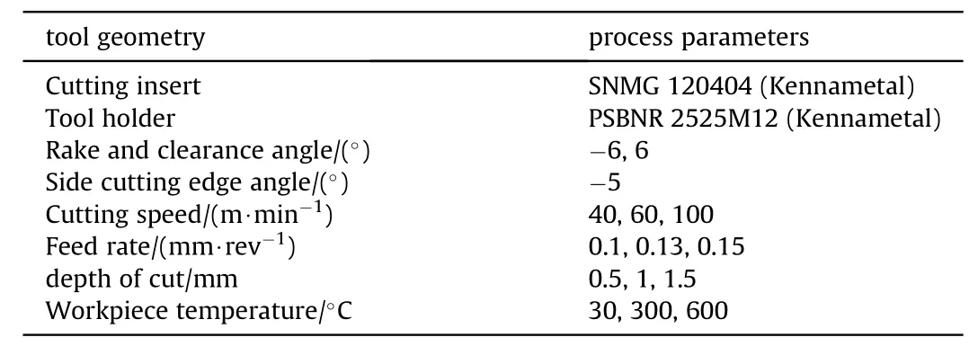
Table 1Tool geometry and process parameters.

The material constants(A,B,C,n,andm)are taken from Ref.[20].The coefficient of friction(μ)value is utilized after conducting the machining test in Coulomb friction law as expressed in Eq.(2)and Eq.(3)respectively.

whereFzis the cutting force,α is the rake angle andFxyis equivalent thrust force and can be evaluated as Eq.(4).

2.2. Experimental validation
To validate the simulation results,an experimental test is performed in turning of Inconel 625 on a conventional center lathe as shown in Fig.2.The composition Inconel 625 and heating method can be found in Ref.[30].The experimental trials are performed with the same cutting simulation conditions.The forces,chip morphology and surface finish(Ra)are evaluated by using dynamometer,optical microscope and profile meter respectively.
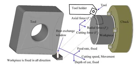
Fig.1.Assembly of cutting tool and workpiece.
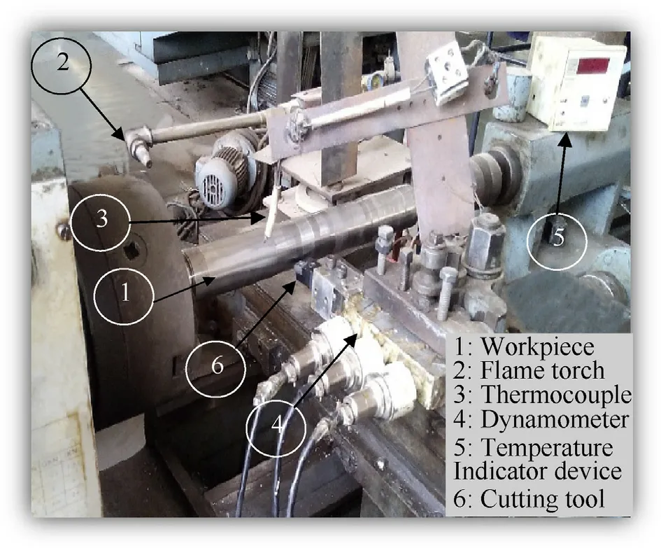
Fig.2.Experimental setups for machining of Inconel 625.
3. Results and discussion
3.1. Simulated forces,stress distribution,temperature and chip formation analysis
The simulated cutting forces are extracted at steady state cutting condition.It is observed reduction in(25%,18%and 12%)simulated cutting(Fz),feed(Fx)and radial force(Fy)at 600°C as compared to 30°C atVc=100 m/min,f=0.13 mm/rev andap=0.5 mm(Fig.3).This is due to the fact that heating effect decreases workpiece strength due to thermal softening.The application of heating increases the shear zone temperature 847°C at 600°C,whereas at 30°C it reaches 776°C.For in-depth analysis the flow stress or effective stress and effective strain at primary shear zone are extracted using point tracking method.Four points(1-4)are taken at the shear zone for 30°C and 600°C temperature(Fig.4).The effective stress of four points at heating temperature reduces at 600°C as compared to 30°C,resulting reduction in forces.Similarly,a set of simulations are carried out for cutting velocity of 40 m/min and 60 m/min,results are compared to experimental findings.A substantial agreement is observed between simulated and experimental forces except 30°C Num(Fy)at cutting speed of 60 m/min and 100 m/min respectively as shown in Fig.5.
It is also observed that at 30°C the chip formed is the segmented type and at 600°C it is continuous;indicating the cutting force generated at 30°C is more fluctuating as compared to 600°C(Fig.3).The average chip thickness formed at 30°C is thicker,and the average chip width is lower compared to chip produced at 600°C.The reduction in chip thickness at 600°C is an indicator of an increase in shear angle,thus resulting in a reduction in cutting forces as compared to 30°C.The collected chips are examined under an optical microscope to study the chip morphology.The chips produced at a different heating temperature and their magnified optical images are shown in Fig.6.The simulated and experimental chip parameter(chip thickness and chip width)are presented in Fig.7.
3.2. Effect of heating temperature and cutting parameters on experimentally obtained forces
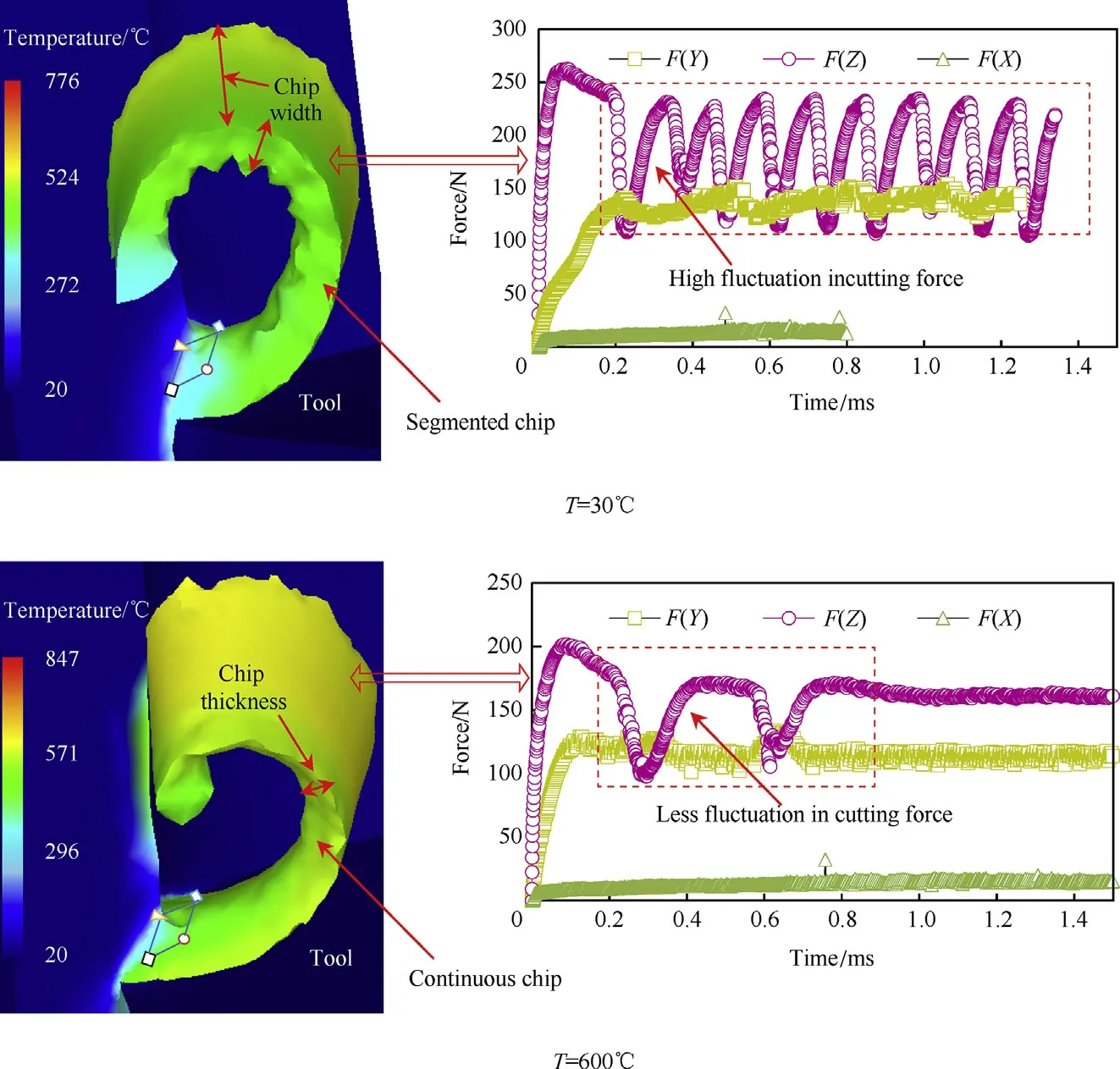
Fig.3.Simulated chip formation and force at room and hot condition.
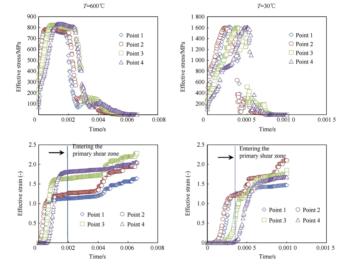
Fig.4.Point tracking of at shear zone and its effect on effective stress and strain at a different cutting speed.

Fig.5.Error%between simulated and experimental forces for room and heating condition at f=0.13 mm/rev and ap=0.5 mm.
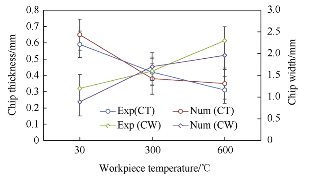
Fig.7.Error%between simulated and experimental chip parameters.
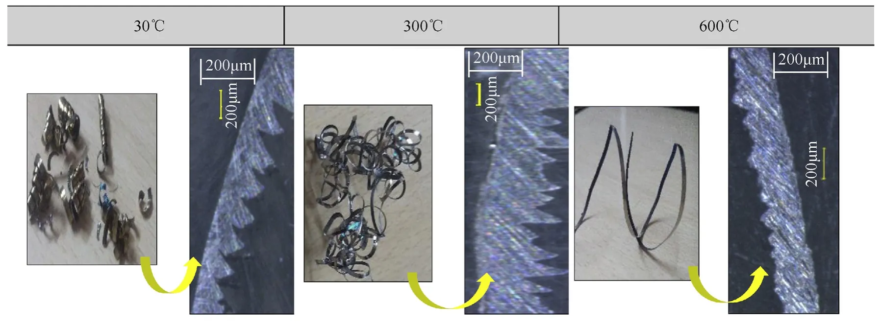
Fig.6.Formation of different types of chips and their optical images at different heating conditions(Vc=40 m/min,f=0.13 mm/rev and ap=0.5 mm).

Fig.8.Effect of cutting speed on(a)cutting force(b)feed force(c)radial force at f=0.13 mm/rev and ap=0.5 mm.

Fig.9.Effect of feed rate on(a)cutting force(b)feed force(c)radial force at Vc=100 m/min and ap=0.5 mm.

Fig.10.Effect of depth of cut on(a)cutting force(b)feed force(c)radial force at Vc=100 m/min and f=0.13 mm/rev.

Fig.11.Variation of(a)Tool life(b)Flank wear at f=0.13 mm/rev and ap=0.5 mm.
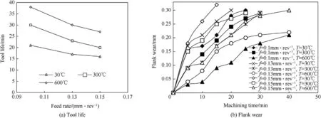
Fig.12.Variation of(a)Tool life(b)Flank wear at Vc=100 m/min and ap=0.5 mm.

Fig.13.Variation of(a)Tool life(b)Flank wear at Vc=100 m/min and f=0.13 mm/rev.

Fig.14.Tool wear at f=0.13 mm/rev and ap=0.5 mm.
In the first case,the variation in forces is recorded by varying cutting,temperature and keeping the depth of cutting and feed rate constant and the results obtained are shown in Fig.8(a-c).There is(29.96%,29.38%and 29.36%)reduction in cutting force,(14%,21%and 28%) feed force and (33%, 46% and 36%) radial force at respective cutting speeds,machining at 600°C compared to 30°C.However,increasing the cutting speed,there is again a reduction of cutting force(18%,19%and 17%),feed force(13%,20%and 27%)and radial force(38%,31%and 41%)at corresponding temperatures respectively.
In the second case,the forces are recorded machining at room and hot condition by keeping cutting speed and depth of cut constant,but varying feed rates.There is a reduction in cutting force(36%,34%and 35%),feed force(18%,27%and 16%)and radial force(33%,46%and 36%)at respective feed rate.With increasing the feed rate,there is an increase in cutting force(17%,38%and 19%),feed force(24%,27%and 28%)and radial force(33%,28%and 20%)at a respective temperature(Fig.9).It is observed that all forces are increased with the increase in feed rate for all ranges of temperature of the workpiece.
In the third case,machining trials are carried out by varying depth of cuts and keeping cutting speed and feed rate constant.Machining from 30°C to 600°C temperature,there is a reduction in cutting force(17%,15%and 15%),feed force(20%,14%and 29%)and radial force(44%,54%and 50%),at a respective depth of cut.There is an increase of cutting force(9%,14%and 12%),feed force(40%,25%and 25%)and radial force(33%,28%and 20%)at respective temperatures with rising in the depth of cut(Fig.10).
3.3. Effect of heating temperature and cutting parameters on tool life and tool wear
The effect of cutting speeds on tool life and corresponding flank wear with the heating temperature are performed.There is an increase of 209%,161%and 238%in tool life at respective cutting speeds,at 600°C compared to 30°C.However,increasing the cutting speed from 40 to 100 m/min,a reduction of 38%,10%and 32%in tool life at 30°C, 300°C and 600°C workpiece temperature respectively(Fig.11).At high cutting speed,there is an increase in cutting zone temperature which again reduces the strength of the material resulting in reducing tool wear.
There is 81%,76%and 62%increase in tool life at a respective feed rate,from 30°C to 600°C as shown in Fig.12(a-b).It is observed that the tool life is decreased by(23%,33%and 31%)at 30°C,300°C and 600°C respectively,when feed rate increases.At high feed rate,sufficient heat is not transferred to the cutting zone in a hot turning[15].
Machining Inconel 625 from room temperature to 600°C,the tool life increased by 120%,107%and 75%at a depth of cuts of 0.5 mm,1 mm and 1.5 mm respectively as shown in Fig.13(a-b).But increasing the depth of cut from 0.5 mm to 1.5 mm,there is a decrease in 20%,17%and 36%in tool life at respective temperatures.
Wear formation in the room and hot turning at different cutting speed are shown in Fig.14.The average crater wear formation at 30°C is more compared to 600°C.Build-up-edge(BUE)and chipping formation occur in both room and heating conditions.
3.4. Effect of cutting parameters and workpiece temperature on surface roughness
The surface roughness value is decreased with increased heating temperature.40%,27%and 42%decrease of surface roughness at respective cutting speed in 600°C to 30°C temperature.When cutting speed is increased the surface finishes value is increased,by reducing surface roughness around 44%,36%and 33%at respective temperatures (Fig. 15(a)). Similarly, machining Inconel 625 at 600°C,the surface roughness decreases by 40%,19%and 37%at respective feed rates compared to 30°C(Fig.15(b)).The surface roughness value is decreased 17%,23%and 37%with heating temperature 600°C compared 30°C at a respective depth of cuts.Surface roughness increased by 14%and 32%at 30°C and 600°C with the increase of depth of cut(Fig.15(c)).
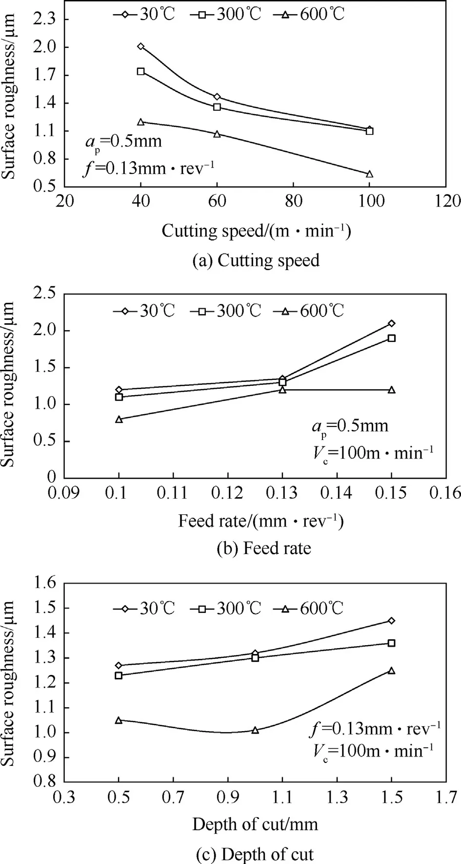
Fig.15.Variation of surface roughness with(a)cuting speed(b)feed rate(c)depth of cut.
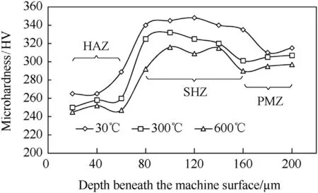
Fig.16.Microhardness below the machine surface at Vc=100 m/min,f=0.13 mm/rev and ap=0.5 mm.
For measurement of micro-hardness,the workpiece is cut using wire electro-discharge-machine and polished by polishing machine.The machined subsurface is measured from the edge towards the center of the sample with an equal interval,i.e.,20 μm.The micro-hardness of the machined below the machined surface is decreased(up to 60 μm)with an increase of workpiece temperature,and the material becomes softened due to annealing at heat affected zone(HAZ).Moving from 60 μm to 160 μm the annealing is decreased,strain hardening zone(SHZ)is formed,and microhardness value becomes higher.When shearing and plastic deformation decreases,it is observed that the hardness value reached to its parent material zone(PMZ),i.e.,320 HV.It confirms the increase of workpiece temperature reduces the strain hardening effect during machining.The measurement of micro-hardness beneath the machined surface and corresponding values is shown in Fig.16.
4. Conclusion
In this paper,the effect of heating temperature on the forces,chip morphology parameters has been studied using FEM.The simulations are carried out using heat exchange window.To verify the simulation results an experiment trial has been performed.The following conclusion has been drawn on the work as follows:
·The forces exerted on the cutting tool are lower at heating compared to room temperature machining conditions.The increase of heating temperature reduces the chip thickness and increase the chip width than the chip produce at room temperature.
·The simulated chip formed at room temperature is the segmented type,whereas at 600°C it is continuous type chip.
·Highest tool life is observed at higher cutting speed with high heating temperature condition.Adhesion,notch wear,and builtup-edge formation are observed at both room and heating temperature condition.
·Surface roughness is mostly affected by cutting speed and least affected by the depth of cut. The micro-hardness value is decreased at heat affected zone,whereas the value is increased at strain hardening zone.
·The simulation results such as forces,chip thickness,and chip
width are partially validated with the experimental findings.
杂志排行
Defence Technology的其它文章
- Round robin using the depth of penetration test method on an armour grade alumina
- Sonochemically assisted synthesis of nano HMX
- Effect of particle gradation of aluminum on the explosion field pressure and temperature of RDX-based explosives in vacuum and air atmosphere
- Study on liquid-filled structure target with shaped charge vertical penetration
- Thermal decomposition of ammonium perchlorate catalyzed with CuO nanoparticles
- Investigating the dynamic mechanical behaviors of polyurea through experimentation and modeling
