Experimental investigation of pulse gas flow during the pulse-jet cleaning of a ceramic filter candle
2019-12-13ZHAOXianyiCHOIJoohongJIZhongli
ZHAO Xianyi, CHOI Joohong, JI Zhongli
(1. School of Innovation and Entrepreneurship, Bohai University, Jinzhou 121013, China;2. College of Engineering, Gyeongsang National University, Jinju 660-701, Korea;3. School of Mechanical Transportation Enigeering,China University of Petroleum,Beijing 102249, China)
Abstract:Around pulse nozzles, the pulsed gas will be oscillated accompanied by under-pressure. It is an interesting problem because it can improve the jet pulse effect through the loss of surrounding clean gas. However, the theories proposed by them were not fully supported, so far, in the careful experimental units for the real system. The commercial filtration device as cold bench ceramic filters was utilized to investigate the transient pressure distribution of pulse gas around the nozzle in this study. Differential pressure around the pulse nozzle was measured in the process of pulsed gas injection and the maximum or the minimum pressure was traced to visualize the pulse gas flow. The formation of negative pressure during the pulse gas injection was observed around the pulse nozzle. And the pulse propagation of the oscillation wave was observed during the expansion process when the pulse gas left the pulse nozzle and its phenomena observed in the experimental results showing qualitatively good agreement with the simulation results .
Keywords:oscillation wave; pulse-jet; entrainment effect; filter candle; transition pressure
0 Introduction
During the filtering process, particles usually deposit as particulate cakes on the surface of the filter and increase pressure drop as gas permeates.For the filtration process to be continued, filter medium should be periodically cleaned effectively by pulse-jet cleaning to remove the ash cake deposited on the outer surface of the filter candle, a process called surface regeneration. Many workers〔1-8〕have been interested in the improvement of the regeneration efficiency of pulse-jet cleaning on the filter element. Importantly, the momentum of pulsed gas in the filter chamber is uniformly formed along the filter element length in order to ensure that the filter element is adequately cleaned〔6〕. Moreover, not the whole filtration area is exposed to pulsed gas and not the whole dust cake is stripped from the exposed region in general〔9〕.
One of the reasons for the partial insufficient cleaning of the filter element is the formation of dead region located only near the open part of the filter element where the pulse cleaning effect could be neglected due to the development of the negative-pressure〔6,10〕. The initial airflow of the pulsed gas leaving the pulse nozzle generates a low pressure region near the pulse nozzle and brings about sucking momentum, which results in a secondary airflow〔11-12〕.The generation of the secondary airflow is beneficial to the working of the ceramic filter. Nevertheless, the disadvantages can be supplied when the sucking effect is extended into the filter element, which results in the negative-pressure inside of the filter element to cause the suction of the dust gas during the regeneration of itself.
The oscillation of propagation gas after leaving the pulse nozzle during the pulse gas injection is proposed a few workers〔13-14〕. Berbner and Löffler〔13〕reported that an oscillation of the pulsed gas occurred on top of the ceramic fabric filter with the zero value on account of the process gas. Zhang et al.〔15〕investigated wave propagation in the process of pulse jet cleaning and analyses the formation of entrainment effect around nozzle exit by CFD calculations. The objective of the work is to discuss the flow dynamics of pulsed flow gas and find out the oscillation phenomenon mechanism of the pulsed jet gas for a ceramic filter candle. In addition, the results of experimental investigations were analyzed with the numerical results proposed by Zhang et al.〔15〕during pulse-jet cleaning.
1 Experimental
The experiment was executed in a bench scale unit as shown in Fig.1. Pall-Schumacher filter (Dia-Schumalith 10-20) of 1.5 m long (inlet and outlet diamenters are 40 and 60 mm, respectively) were detailedly fixed on the tube sheet and severally cleaned with a pulse-jet gas. The designed target is to realize the maximum jet momentum as being operated to farthest decrease the loss of the pulsed cleaning gas. The storage capacity of the compressed air is 0.0309 m3and keeps the pulse-jet a given pressure. The convergent nozzle locates on the top of diffuser. The shape and the notations of the nozzle and diffuser are denoted in the detail figure of Fig.1. The inlet (Di) and outlet (Do) diameters of nozzle are 16 and 12 mm, respectively. And the convergent height (h1) and convergent angle (α) of the nozzle are 11 mm and 11°, respectively.The inlet (Φi) and outlet (Φo) diameters of diffuser are 70 and 35 mm, respectively.The height(h2) of diffuser is 100 mm.
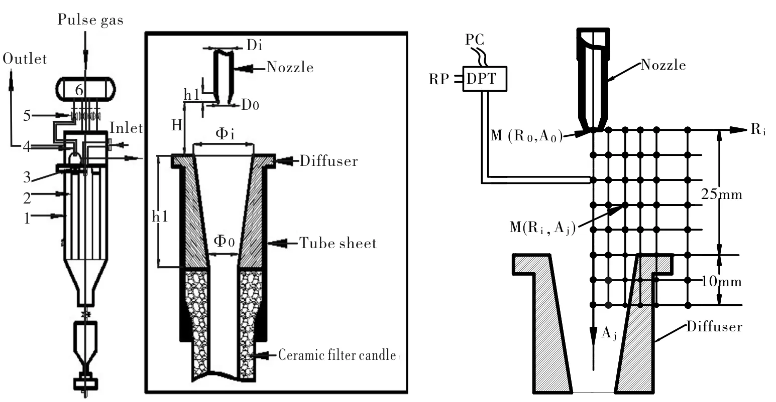
Fig.1 Diagrammatic sketch of filter unit;1.filter unit; 2.filter candle;2.diffuser; 4.nozzle;5.solenoid valve; 6. air reservoir Fig.2 Measurement position of DP around nozzle exit and diffuser; diffuser pressure Transmitter(DPT), measurement position(M(Ri,Aj))
Differential pressure around the convergent nozzle (DP) denotes the pressure difference between that at a certain position and that of background of the clean chamber where the pressure is not disturbed as the pulsed gas injecting. The measurement domain is constructed in two dimensional area and composed of the axial and the radial direction based on the center of the nozzle outlet. The measurement point is expressed in M(Ri, Aj), where i and j denote the distances from the center in the radial and the axial direction, respectively, as shown in Fig.2. That is, M(R0, A10) denotes the position 10 mm far from the nozzle outlet in the axial center line of the nozzle. Total distance from nozzle to diffuser is 25 mm but the measurement positions are extended to that of 10 mm below the top of diffuser. The trace of DP at a given position was recorded in a personal computer (PC) in the time variance during the injection of the pulse air. Pressure of every position was guided along the stainless steel tube of 6 mm into the differential pressure transmitter as shown in Fig.2.
2 Results and discussion
2.1 Entrainment effect of the pulse-jet gas
Fig.3 represents the changes of differential pressure (DP) on the time basis at a certain point near the pulse nozzle along the center line of the axial direction M(R0,Aj) when the pulse-jet gas is applied during 0.6 sec by opening the pulse valve which is connected to the air tank of 5 bar. The results shows the peak pressure is minimum and negative than the background pressure during all the pulse time and for all position from nozzle outlet to the top of diffuser, which means the pulse gas develops the area of lower pressure than background along the center line of nozzle during the pulse gas approaches into the filter cavity. The formation of the negative pressure is the main force to suck the surrounding gas into the primary pulse gas, which denotes the entrainment effect as mentioned by Morris〔11〕and Theodore et al〔12〕.
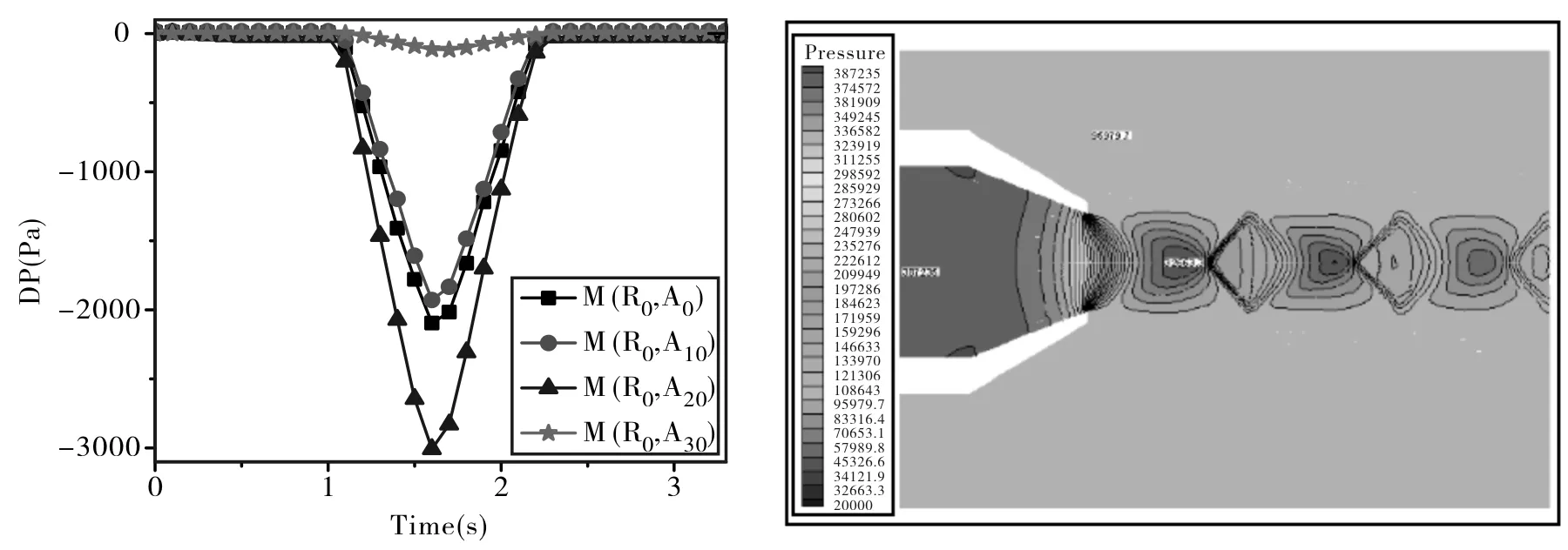
Fig.3 Time dependence of DP changes at several points along the nozzle center line Fig.4 Plot of theoretical pressure contours near the pulse nozzle exit
The theoretical background for the entrainment effect is well described by Zhang et al〔15〕. They constructed the theoretical static pressure contour near nozzle exit during the pulse gas injection as shown in Fig.4. The figure presents that the pulse gas propagates in a form of oscillation pulse with the repeating bundles of the negative and positive pressure. This phenomenon can be explained by the way that, after leaving the pulse nozzle, the pulse gas expands and is decompressed to increase its velocity. And the increasing of the kinetic energy of pulse gas compensates the decreasing of gas pressure, which forms a relatively negative pressure zone in the jet core area.
According to Fig.5, the maximum negative pressure value becomes bigger as the pulse pressure increases from 2bar to 5bar. Fig.5 illustrates the effect of pulse gas pressure on the formation of the negative pressure at the position M(R0,A10) . The stronger negative value of DP means the better entrainment effect. However, the excessive pulse pressure will also spend the extra pulse gas and cause the unnecessary waste. Therefore, the appropriate pulse pressure should be chosen to meet the practical needs. Those results reveal that the negative-pressure region can be formed near the nozzle outlet, which acts as the major driving force to entrain the secondary gas from the cleaning chamber in the pulse-jet cleaning process. The suction effect of the pulsed cleaning plays an important role to improve the pulsed cleaning result and decrease the pulsed gas loss, simultaneously refrain from the strong thermal shock as a result of mixing effect of cold pulse gas with hot gas〔16〕.
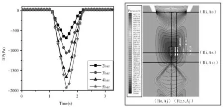
Fig.5 The effect of pulse gas pressure on the differential pressure formation at position M(R0,A10) during pulse-jet cleaning Fig.6 Domain of pulse gas flow for denoting the measurement lines around the pulse nozzle
2.2 The pattern of pulse gas flow along the axial direction of the pulse nozzle
For the sake of visualize the form of the wave propagation of the pulsed gas after leaving the pulse nozzle, we tried to measure the peak differential pressure at many points districted carefully along the axial or radial direction of the domain near the nozzle exit. Fig. 6 shows two axial measuring lines of the center line of the nozzle M(R0, Aj) and of being far 2.5 mm from the center line M(R2.5, Aj). Fig.6 also shows three radial measuring lines M(Ri,A0), M(Ri,A10), and M(Ri,A12.5) which are 0, 10, and 12.5 mm, respectively, away from the nozzle exit.
Fig.7 shows the locus of the peak pressure measured at the positions along the axial directions[M(R0,Aj) and M(R2.5,Aj)]. The locus of the peak pressure composes of the minimum and the maximum peaks during prolong from the nozzle to diffuser. And its peak height weakens as the pulse gas progresses up to the diffuser. The trends of the experimental propagation curves are very similar with the calculated one from the simulation data of other authors〔15〕. The experimental results also suggest the existence of oscillation diffusion of the pulsed gas after departing from the pulse nozzle. Especially, there is strong negative pressure core around the position of 6 mm from the nozzle exit in this case, so that the stronger entrainment effect will appear in this region.
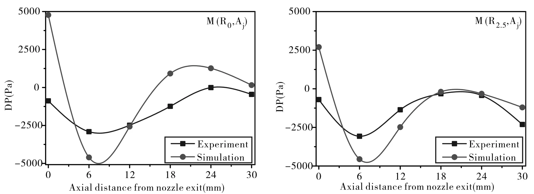
Fig.7 Locus of peak differential pressure along the axial direction for M(R0,Aj) and M(R2.5,Aj)
2.3 The pattern of pulse gas flow along the radial direction of the pulse nozzle
Fig.8 displays the locus of the peak pressure measured at the positions along radial direction of the nozzle for several measurement positions in the axial direction[M(Ri, Aj)]. Because of the lack of the adjusting trial of the simulation program, our experimental results and the simulation data is not completely matching, but the trend of the wave propagation shapes are very similar each other. The main difference is that the peak values of experimental differential pressure shows always negative for the all measurement points but some are positive for the case of the simulation results. By observation, three kinds of similar pressure waveform were discovered in Fig.8.
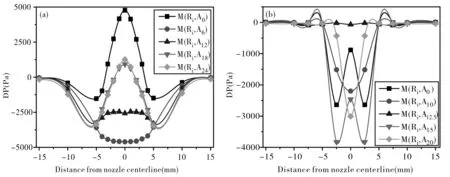
Fig.8 Locus of the peak differential pressure along the radial directions at several axial positions;
First type of waveform is shown in detail at Fig.9, which occurs along the nozzle exit line M(Ri,A0). The nozzle centerline is the core of pulse-jet, with DP measurement points gradually far away from the nozzle centerline, DP will gradually become smaller, so that DP value approach to zero at the point more far 10 mm distance from nozzle centerline. In the simulation result, we can see that the variation window is slightly wide than that of experimental one. So the maximum suction position forms around 2.5 mm and 5.5 mm in the experimental and simulation, respectively. The formation of the strong positive pressure in the center line is not expectable result when we think the strong entrainment occurs along the center line of the nozzle. Our first interest in this study is to identify the oscillation phenomenon and to understand its origin. Zhang et al〔15〕. imagined a shock wave cell structure composed of expansion wave, reflection oblique shock wave, and shear layer at outlet jet core area of the pulse nozzle as shown in Fig.10. The pressure of the pulse cleaning gas will decrease while the velocity will increase at nozzle exit by the gas expansion. The expansion wave intersect and then reach the shear layer, respectively, at the same time, the free-interface reflection shock wave is formed. When the reflection shock wave returns, it is experienced the pressure jumped by compression and the velocity decreases drastically. The repeat of this phenomenon in turn makes the pulse type shock wave.
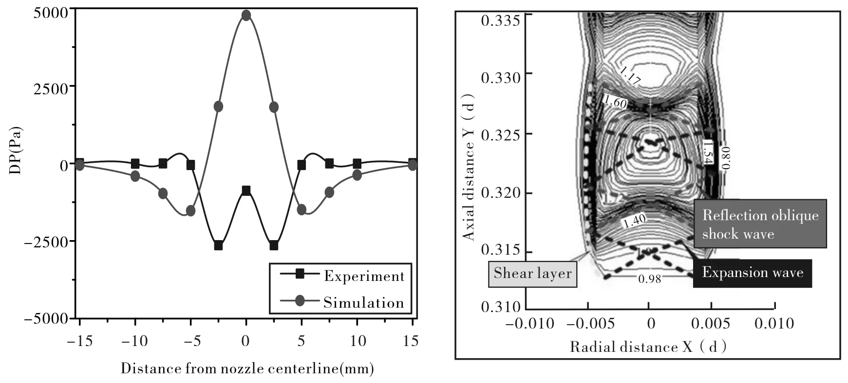
Fig.9 Locus of peak DP at the exit of the pulse M(Ri,A0) Fig.10 The shock wave cell structure nozzle the mechanism of the pulse gas flow
The second type of pressure waveform may be occurred if follow along the line of distance 10 mm from the nozzle tip (M(Ri,A10)) and shows the monotonous increase from the center of the nozzle to outside as shown Fig.11. The positions, along the axial direction from the nozzle exit, denoting this type of wave form are 6 mm and 12 mm in simulation and experimental result, respectively.
The third type of pressure waveform can be imagined if follow along the line of distance 12.5 mm from the nozzle tip (M(Ri,A12.5)). DP change of this line has the first minimum value at center and next negative value again at the point of 7.5 mm far from the center as shown in Fig.12. This kind of waveform is complicated but the region is very short as shown in Fig.6. So the selection of the point for experimental observation is very difficult as the working range is very short.
3 Conclusions
The formation of negative differential pressure at several points compared with the environmental area confirms that the under pressure region is formed nearby the nozzle outlet, which is the major driving force to entrain the secondary gas from the cleaning chamber in the pulse-jet cleaning process.
To visualize the wave propagation of the pulsed gas after departing from the pulse nozzle, we traced the minimum or the maximum differential pressure at the points along the axial or longitudinal direction of the domain near the nozzle exit. Along nozzle exit of the axial direction, pressure wave intensity become more stronger in some area, however, pressure wave intensity become quite weak in others area. Especially, there is strong negative pressure core area between 6 mm pulse distance and 12 mm pulse distance, so that the stronger entrainment effect will appear in this region. Wave pulse propagation was developed during the expansion of the pulse gas after leaving the pulse nozzle and its phenomena observed in the experimental results demonstrated qualitatively good consistency with the CFD simulation reported by Zhang et al〔15〕.
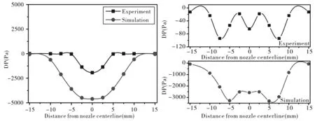
Fig.11 Locus of peak DP at the points; M(Ri,A10)for the experimental and M(Ri,A6) for the simulation Fig.12 Locus of peak DP at the points; M(Ri,A12.5) for the experimental and M(Ri,A12) for the simulation
