Electrodynamic response study on railgun launcher based on electromechanical coupling model
2019-10-31HongchengXiaoDongmeiYinBaomingLi
Hong-cheng Xiao,Dong-mei Yin,Bao-ming Li
National Key Laboratory of Transient Physics,Nanjing University of Science and Technology,Nanjing,210094,China
Keywords:Railgun launcher Sliding contact Dynamic properties Elastic response
A B S T R A C T The electrodynamic behavior of a medium caliber railgun launcher has been studied based on an electromechanical coupling model,which uses a unified modeling method for both electromagnetic and electromechanical field.This model adopts a material equivalent method to simulating the sliding contact behavior for the in-bore armature.An embedded node encoding program during field meshing operation provides good load transfer accuracy between electromagnetic field and mechanical field.Dynamic properties of in-bore magnetic field are firstly simulated and a subsequent dynamic analysis is conducted by mapping element results from electromagnetic analysis step to structure analysis step.The electromechanical-elastic response of the barrel is studied under the excitation current.The numerical model has shown reliability compared to experimental results.
1. Introduction
Since the understanding on the launch dynamic model of the railgun is not clear enough,some theoretical problems remain to be solved before its tactical application[1-5].In the paper,the electrodynamic behavior of a medium caliber railgun launcher has been studied based on the electromechanical coupling model. The coupling model uses unified nonlinear finite element analysis(FEA)files for both electromagnetic and electromechanical analysis.An artificial encoding program on the numbering of the node and element is embedded in the numerical model during its physics field meshing progress.The ordered node encoding rule during FEA operation provides good accuracy for load transfer between electromagnetic field and mechanical field during electromechanical response calculation.The prepared 3-D electromagnetic and mechanical physics files will be simulated in the low frequency electromagnetic module and nonlinear mechanical module.Dynamic distributions of the magnetic field are firstly simulated and a subsequent mechanical analysis under the same time step will be conducted after mapping element results from electromagnetic analysis step to structure analysis step,seeing Fig.1.The quasi ballistic process of armature in bore is simulated by a synchronized iterative computing in each step.The sliding contact status can be estimated during iteration and a new rail-armature contact relation will be created in the next analysis step.The electrodynamic response of the barrel can be analyzed after iterations are finished for the whole launch process.
2. Electromechanical coupling model and the analysis procedure
2.1. Construction of quasi sliding contact model for rail-armature interaction
This model adopts a material equivalent method to simulating the sliding contact behavior between the rail and armature.The moving region of in-bore armature is created as a band before simulation.This region is set as air domain in advance and has a fine contact with the rails at initial launch time,seeing Fig.2.With the predicted value of in-bore armature position at the specific time step,the armature geometry will be reconstructed by accurately selecting out the element entity in the space occupied by present armature material in the moving region.The attributes of the selected elements constructing the armature geometry are then modified and updated to the real armature attributes.For an accurate armature reconstruction in every analysis step,the armature moving area is finely meshed and the nodes of the elements are artificially coded,which can be helpful for element selecting during armature reconstruction,seeing Fig.3.
Fig.1.Electromechanical FEA model.
Fig.2.Air domain around the barrel.
Fig.3.Armature element configuration.
After the rail-armature contact and air domain are well defined,the FEA physics file will be extracted and submitted to transient electromagnetic analysis module for current density and flux density simulation. In every simulation step, the results from electromagnetic analysis will be extracted and loaded into an external subroutine of interior ballistics calculation.This subroutine systemically analyzes the acceleration history of the armature in bore and gives a prediction of armature position in the next analysis step,which will be adopted for rail-armature interaction redefinition and model updating in the next electromagnetic analysis step.After synchronizing all time steps in the electromagnetic and electromechanical FEA files,the analysis results in every time step will be shared between electromagnetic and electromechanical modules.In addition,the new rail-armature contact relation will be estimated in every analysis step.The estimation is a multiple-parameter diagnosis which involves contact load,contact stiffness,film thickness of discrete lubrication and other factors.Estimation results on rail-armature contact status in previous step will be used as the initial status for the next electromagnetic and electromechanical analysis step. The electromechanical-elastic response of the barrel can be acquired by the above time discrete analysis program after discharging current wave from pulse forming network(PFN)is tested during railgun shot.
2.2. Acceleration performance prediction of the launcher
This study systemically analyzes the acceleration history of the in-bore armature and acceleration performance of the launcher is predicted mainly by the following steps[6]:
(1)Assume the location,velocity and acceleration of armature at present titime step,are known asConduct one electromechanical analysis step at present time step with above FEA model and extract the armature driving forcenormal contact stress
(2)Calculate the acceleration value of the armature,for next i+1 time,is the rail-armature friction force andis aerodynamic drag of the armature.
(3)Compute the velocity value of the armature,for next i+1 time,
(4)Compute the displacement value of the armature,for i+1 time,
The rail-armature interaction during railgun shot includes tangent friction and normal contact force,seeing Fig.4.The railarmature friction force during a shot can be estimated as the following equation,
Where,ferefers to the external drive force on the armature.fnis the normal stress on the rail-armature contact surface, fsis the maximum steady-state friction force.p is a ratio coefficient relating to rail-armature friction power.p1and p2are the key values representing lubrication level.The friction coefficient used in the study is simplified to a function of rail-armature friction power[7],seeing following Fig.5.
2.3. Program implementation based on FEA code development
A visual finite element analysis(FEA)platform by C#code design language,combined with Ansys computing core has been developed to design a graphical program“Emag_launcher.exe”,for the electromechanical coupling analysis on the railgun barrel.Ansys provides effective field calculation for different physical environments.The sliding contact process and ballistic parameter calculation process are developed separately as subroutines and will be repeatedly called by the designed C#main interface.The most important feature of this code includes transient magnetic field calculation,rail-armature coupling mechanics and internal ballistic calculation.The main program includes a pre-processing unit for multi-parameters recording and physics files forming,a FEA solver unit for parametric model analysis and optimization.The simulation unit mainly includes electromagnetic module,electromechanical module and electro-thermal analysis module.In the post-processing unit,the results data document is processed to realize visualization and digital railgun simulation,seeing Fig.6.This code provides the basis for the fast electromechanical analysis on the composite railgun barrel.
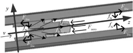
Fig.4.Force diagram of rail-armature interaction.
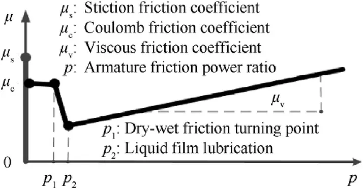
Fig.5.Rail-armature friction mode.
3. Electromagnetic analysis on an augmented railgun barrel
3.1. Electromagnetic field distribution on the composite barrel
A medium caliber railgun launcher is analyzed in the study.The barrel of the launcher has a 45 mm caliber and double turn rails in the bore.The rails and side wall are tightly packaged into glass fiber and T800 fiber wraps.The elliptical contour of bore and external package are shown in Fig.7.The discharging current from PFN is a pulse which has a megampere amplitude and a millisecond duration,seeing Fig.8.The current density on the main rail are solved by the program and distributions at 1.80 ms and 2.60 ms are shown in Fig.9.The maximum current density generates in the back of the armature and the inner face of the main rail,which shows skin effect leads to energy concentration along the internal contour of the bore[8].The magnetic flux density distribution in the longitudinal section of the barrel is shown in Fig.9.Magnetic induction at present current level is about 24 T for double turn structure and no flux propagates into the external wraps of the composite barrel,as shown in Fig.9.The magnetic flux density remains about 3T near the outer layers of the carbon fiber,but this value decreased to 0.02 T in the outer glass fiber layer.
3.2. Electromagnetic properties estimation of the launcher
The structure characteristic of the rail-armature circuit is shown in Fig.10.The breech circuit contains two loops,including Turn 1 and Turn 2 in the figure.The muzzle circuit contains a Turn 3 loop.The electromagnetic properties of the augmented railgun launcher are estimated by the post processing part of the FEA platform.Two discharging pluses are analyzed in this part.Discharging current_1 is 1120 kA with a 4.2 ms duration.Discharging current_2 is 960 kA with a 5.1 ms duration,shown in Fig.11.The driving force history on the armature has been calculated by the FEA code.The maximum propulsion on the armature is 529 kN by current_1 and 422 kN by current_2 respectively,as the curves shown in Fig.11.Numerical simulation gives the transient voltage across the rail-armature circuit,which is induced by the circuit resistance under discharging excitation,as shown in Fig.12.The breech voltage rises to kilovolt level due to strong skin effect and eddy current effect.
The total breech voltage and muzzle voltage under the transient field satisfy the following formulas,
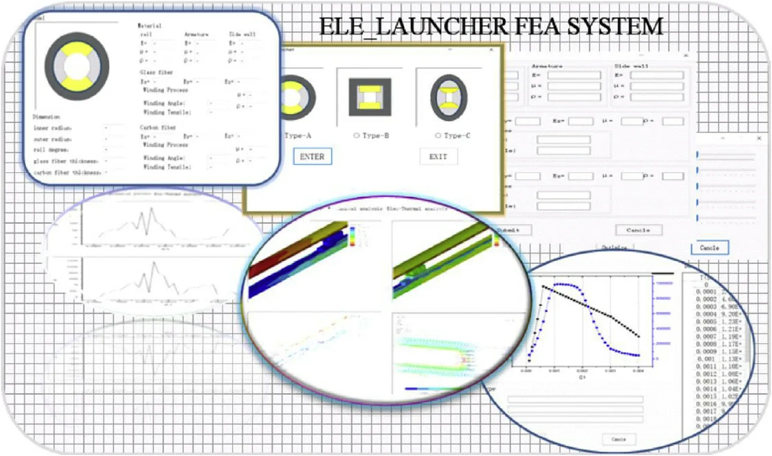
Fig.6.Visual FEA platform for railgun barrel simulation.
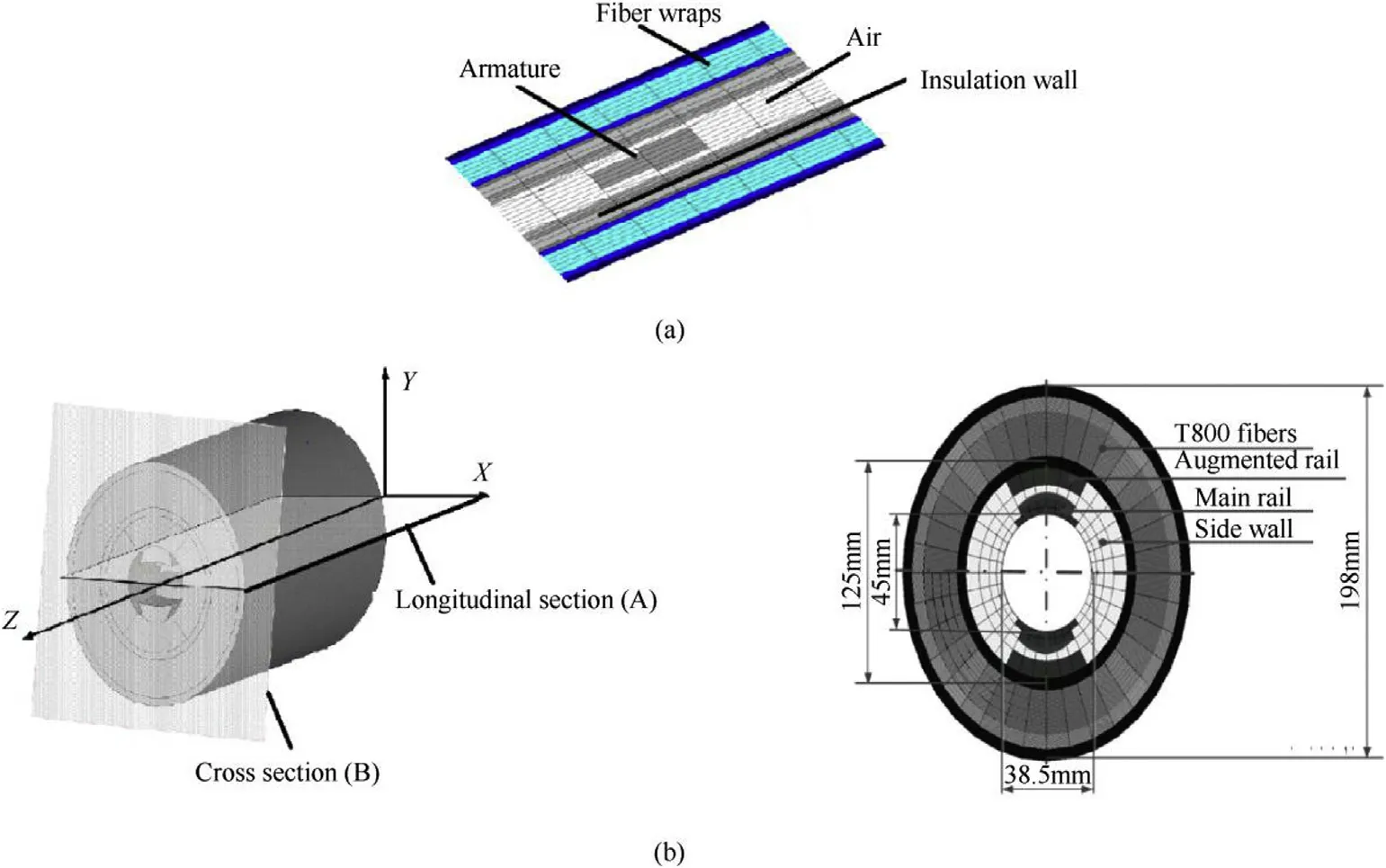
Fig.7.Barrel structure of a 45 mm caliber,double turn railgun.
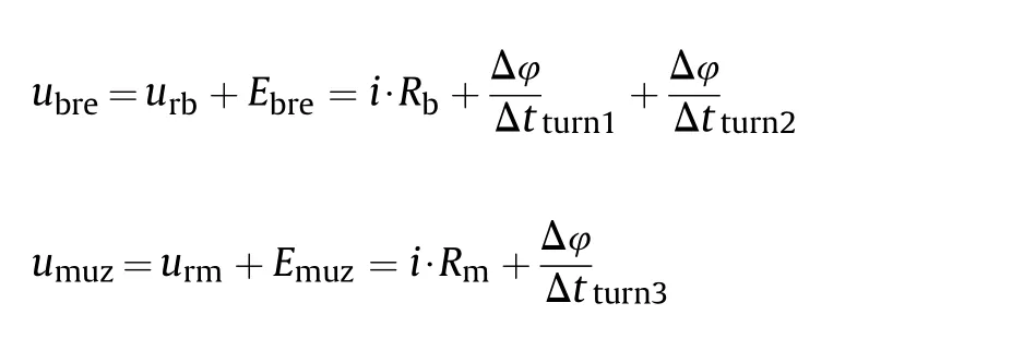
Where,ubreand umuzare total voltages on the breech and the muzzle.urband urmare resistance-voltages across the breech circuit and muzzle circuit.Ebreand Emuzare induced electromotive forces across the breech loop and muzzle loop.The total muzzle voltage is usually taken as a basis for judgment of rail-armature fine contact in previous studies[9-10].So the FEA post processing part gives the computation of the total muzzle voltage.The back EMF in
Turn 3 is calculated as,
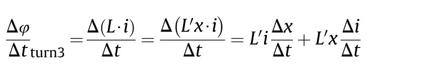
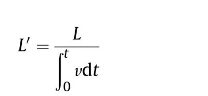
Where,L is the inductance coefficient of Turn 3 circuit.L′is the inductance gradient along the rail length direction.The first item on the right of the equal sign can be modified as,

Where,S is the area of Turn 3 loop with a unit length in rail length direction.l is the spacing between the inner rails.This infers that the back EMF on the muzzle is a superposition of two parts.is current_1 and current_2 have been calculated and illustrated in Fig. 13 based on the superposition of above two voltage components.
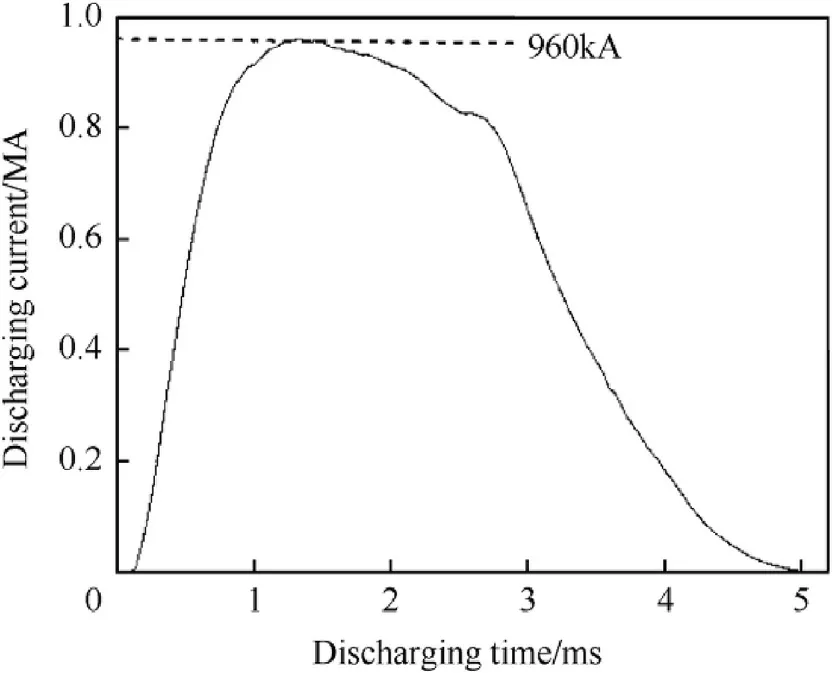
Fig.8.Discharging current.
The acceleration performance of the rail launcher has been studied by the coupled subroutine of interior ballistics calculation.In the interior ballistics process,the time-varying power and energy integral of the armature,total power and energy injected to the launcher are computed respectively.The efficiency of the rail launcher can be expressed as the following[11],
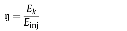
Fig.9.Current density and magnetic flux density in the contact zone(in the longitudinal section,time=1.80 ms、2.60 ms).
Fig.10.Structure characteristic of the rail-armature circuit.
The launching efficiency of the barrel is 18.9%under discharging current_1 and 21.8%under discharging current_2 by estimation,seeing Fig.14.An optimized discharging current may improve the launching efficiency by reducing the residual electric energy after the motional electromotive force andis the induced electromotive force. The total muzzle voltages under discharging projectile passes the muzzle by comparing the two current models.The acceleration performance of the barrel under above current excitations is shown in Fig.15.2201 m/s and 1970 m/s of armature velocities are achieved by excitation current_1 and current_2,which infers that higher peak current has better acceleration capability if overload in the railgun bore is well handled.
The double turn and half-double turn structure are analyzed here for magnetic improvement study[12].As shown in Fig.16.Type_1 barrel has a 2.2-m-long augmented rail near the breech and type_2 barrel has a full-size augmented rail.The magnetic flux density behind the armature is investigated under 1 MA excitation current.24 T level of induction intensity is created by type_2 barrel,
Fig.11.Discharging pluses and electric propulsion histories.
Fig.12.Transient voltage across the rail-armature circuit.
The incremental inductance of the barrel during railgun shot is investigated and recorded in Fig.17.The double turn structure has a 1.07 μH/m inductance while a single turn structure has a 0.38 μH/m inductance.The augmented rail has obvious effect on improving the transient in-bore flux, which is beneficial for armature acceleration.
3.3. Acceleration performance under different discharging current excitations
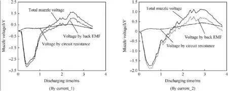
Fig.13.Total muzzle voltage based on the superposition of two voltage components.
but the intensity is reduced to 7.5 T by typ_1 barrel in its front half of the bore.The incremental inductance of the barrel is expressed by the following[13],
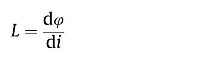
Where,φ is the transient flux in the railgun bore,i is the current flow through the rail-armature circuit.The inductance gradient of the barrel is derived as,
Further investigations on the acceleration capacity of the armature in bore have been conducted by the program[14].Two groups of armature acceleration histories under different discharging pluses are analyzed.The first group is statistics on a 560 g of aluminum armature accelerated by current of 950—1100 kA.Another group is investigations on a 960 g of armature accelerated by excitation current of 1250—1550 kA,seeing Fig.18.The interior ballistic process of armature in bore has been simulated and muzzle velocities of the armature under each excitation conditions are listed in Table 1.According to the numerical result,muzzle velocity of the armature will increase by about 20%with a full-size double turn barrel,compared to a half-augmented barrel.A high amplitude narrow pulse of discharging current will produce much better accelerating performance.And the length of the barrel in the electromagnetic launcher can be effectively shortened based on the effective length of its accelerating region.
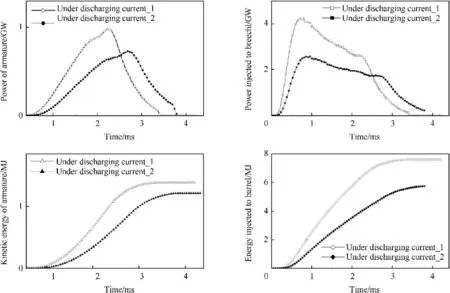
Fig.14.Armature power vs.total power and armature kinetic energy vs.total energy.
Fig.15.Acceleration histories of the armature.
Fig.16.Diagram of augmented structure in type_1 barrel and type_2 barrel.
4. Forced response of the railgun barrel under electrodynamic force
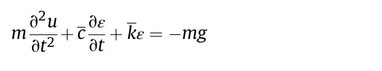
The transverse vibration equation of fiber reinforced railgun barrel under time varying electrodynamic force can be estimated as the following[15]:
Fig.17.Incremental inductance of type-1 and type_2 barrel during railgun shot.
Where,C*I is damping coefficient related to the strain rate of the composite barrel.FAis the force transferred from rail-armature dynamic contact.
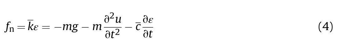
Where,fnis the normal contact force on the rail-armature interface.FRis the time varying repulse force on the rail and can be expressed as,
Fig.18.Two groups of propulsion pluses for armatures.
Table 1 Railgun acceleration performance with different rail and armature structures.
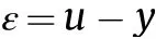
Where,q is the distributed repulse fore on the rail.H(x)is a step function.The armature is treated as a spring-quality-damper dynamic system and its impacting on the rail in the normal direction satisfies the following equation,
Where,u is the radial displacement of armature in the longitudinal plane.is armature contact damping.is the normal contact stiffness between rail and armature.ε is the relative displacement of rail-armature in the normal direction,
The normal contact face can be derived as,
Considered that the interference fitting between rail-armature is artificially constructed during the barrel assembling process,the radial displacement of armature u can be approximated as the following,
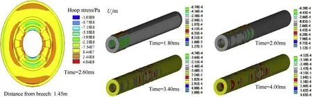
Fig.19.Hoop stress in the cross section(time=2.60 ms,peak current=1120 kA)and radial deformation in the railgun bore(time=1.8 ms,2.6 ms,3.4 ms and 4.0 ms).
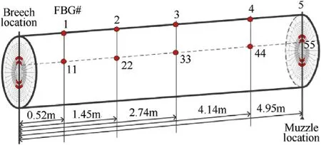
Fig.20.Strain probe points on the augmented composite barrel.
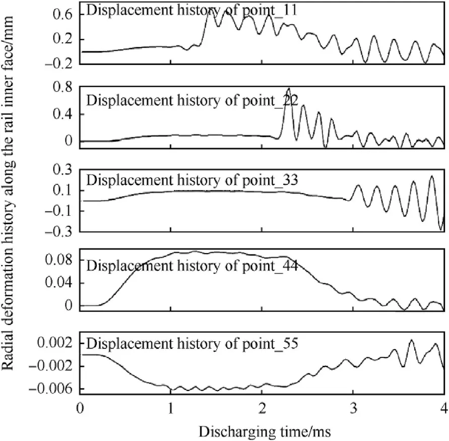
Fig.21.Maximum radial deformation history on the bottom face of the main rail(peak current=960 kA).
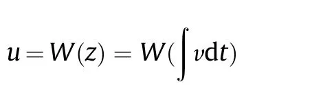
Where,W(z)is the interference on the rail-armature contact.The forced radial response of the railgun barrel during shot can be evaluated by the joint-solution of Eq.(1)to Eq.(4).In present study,the forced response of the barrel under electrodynamic force and rail-armature interference fitting force are simulated by the FEA system which is further developed based on Ansys software platform.The dynamic response of the 45 mm caliber barrel under 1120 kA excitation current is simulated.Fig.19 shows the hoop stress distribution at 2.6 ms in the cross section which is 1.45 m from the breech during railgun shot.The maximum stress is about 1000 MPa appearing near the inner edge of the main rails as the skin effect produces serious current concentration here which results in serious stress concentration.The same thing happens to the augmented rails and about 720 MPa compressive stress exists in the inner edge of the rails.The maximum tensile stress on the rail-side wall interface is about 250 MPa.The radial deformation of the barrel,especially the outward expansion of the bore has significant effect on the rail-armature contact performance,which may lead transition if severe radial deformation happens in bore.The program conducts a survey on the transient radial deformation of the barrel based on real-time load transfer analysis.The radial deformation cloud diagrams of the barrel at four moments are listed in Fig.19.Due to the non-uniform pressure in bore,the barrel has large radial expansion in the longitudinal cross section and obvious radial compression in the horizontal section.The maximum radial displacement of the rail at 1.80 ms reaches about 1.08 mm,which is located in the bottom surface of the main rail due to electromagnetic pressure and interference fit on the rail-armature contact[16-17].
The forced response of the barrel has been simulated with a discharging current of 960 kA injected into the main rail.Ten locations are selected as strain probe points which are evenly distributed on the inner surface of the rail and outer surface of the carbon fiber winding layers,as shown in Fig.20[18].The timevarying deformation of the barrel at these probe points are shown in Fig.21.The caliber of the barrel varies rapidly during launch.The maximum radial displacement on the main rail reaches about 0.7 mm near the breech.The hoop stress history in the outer surface of the fiber and Mises stress history in the bottom face of the rail are listed in Fig.22.The stress histories in point_33 and point_44 show that a continuous pressure pulse exists in the front section of the barrel during the whole launch process.Due to the prolonged electromagnetic force in the whole augmented rail,the bore components may be weakened as the repulsive force is persistent in the barrel during launch.So,special considerations should be given during the strength design and vibration design of the augmented railgun barrel.
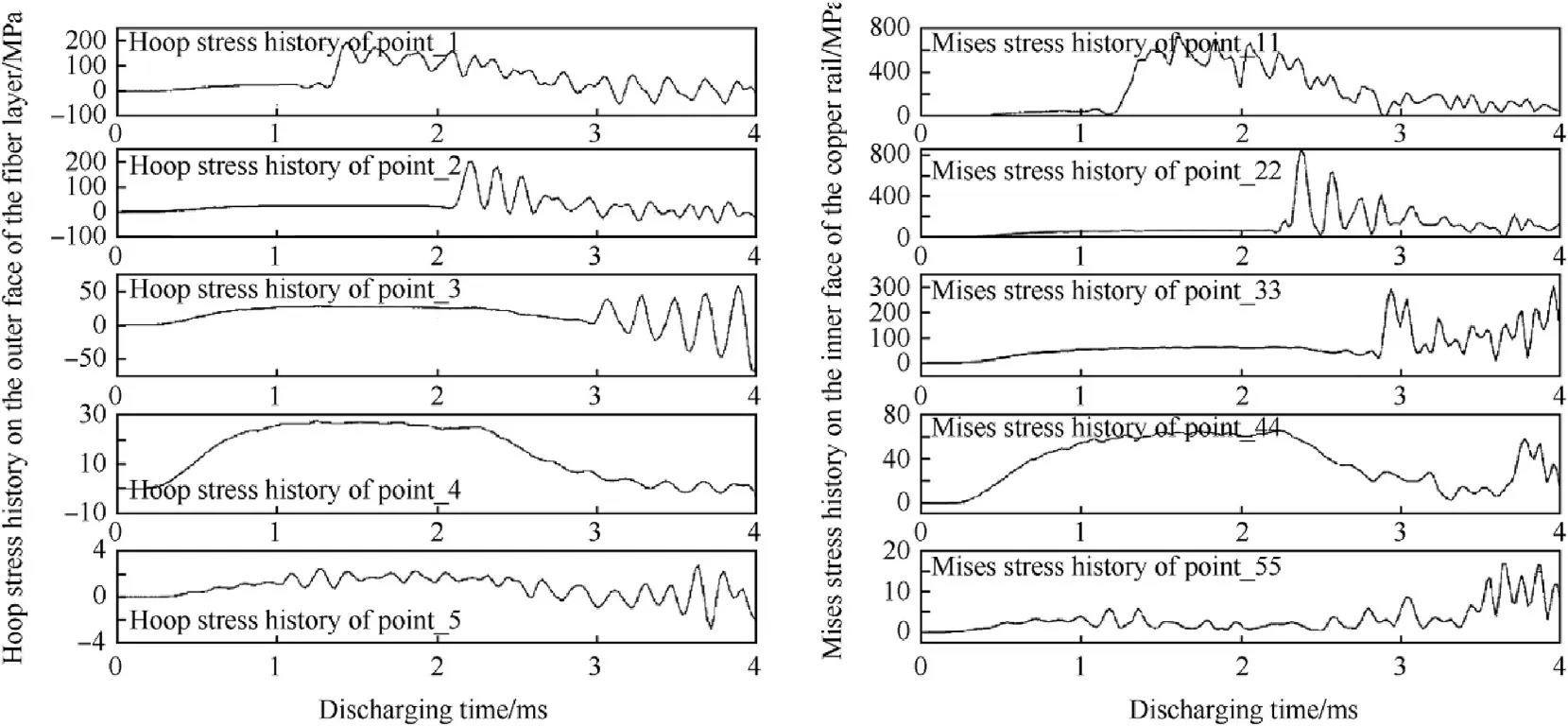
Fig.22.Hoop stress history on the outer surface of the fiber layer and Mises stress history on the bottom surface of the main rail(peak current=960 kA).
Fig.23.Experimental test arrangement on a 45 mm caliber augmented railgun(peak current=1.2 MA,pulse duration=4.1 ms,armature mass=960 g).
5. Experimental tests
Experimental tests have been conducted on a 45 mm caliber augmented railgun barrel.The exciting current from the pulse power supply has a 1.25 MA peak value and 4.2 ms duration,seeing Fig.24.Voltage distribution characteristic on the rail,stress characteristics in the fiber layer and muzzle velocity of the armature are also tested by the dynamic measurement system in the launching center,seeing Fig.23.Accelerating history has been tested by probes and muzzle velocity of the armature reaches about 1875 m/s in the first group of 10 shots.Our simulation result is about 1993 m/s for this energy stage and the difference is currently attributed to the lack of cognitive on the internal ballistic process of in-bore armature.
Fig.24.(a)Current and armature velocity,(b)Voltage characteristic of the barrel.
Fig.25.Hoop stress-time history at point_1.
The experimental breech voltage and muzzle voltage are acquired for comparing with the result from the numerical model,seeing Fig.24.The dynamic hoop stress of the barrel is tested by fiber grating sensors which are installed on the outer surface of the fiber layer.Comparison on the experimental and theoretical value of hoop stress at point_22 has been given in Fig.25.The electrodynamic model in presented study shows good reliability and precise according to the comparative analysis between the experimental and numerical data.
6. Conclusions
The launch dynamics of a 45 mm caliber railgun launcher has been analyzed based on the electromechanical coupling model.The augmented railgun launcher produces about 450 kN driving power on a half a kilo of aluminum armature at 1 MA current level.The inductance gradient of the full-length augmented railgun structure is 2.8 times more than the gradient value in the single-turn structure,as the calculated result is 1.07 μH/m and 0.38 μH/m for both of them.The augmented type has about 20%launch efficiency and this is considered to be a normal performance compared to other rectangular-bore high inductance railgun. The exciting current caused stress concentration on the rail surface.1 MA peak current produces near 1 GPa equivalent stress on the innermost surface of the main rail,which has taken up more residual strength of the copper rail and will induce fast wear damage progress.This infers that a better profile of bore contour is important and internal convex contour of rail might reduce stress amplitude here in the middle of the rail surface.The numerical model proposed in the study has shown reliability compared to experimental results in our shot tests.However,errors in the accelerating performance evaluation shows an in-depth understanding on the rail-armature contact behavior should be proposed,especially considering more about thermodynamics in rail-armature contact. The dynamic response of the augmented railgun may be special as two pairs of vibration barrels exist in the bore and it should be further examined before its tactical application.
杂志排行

Defence Technology的其它文章
- Defence Technology
- Effect of tongue clearance on hydraulic performance of double support vortex pump
- Electroless nickel fabrication on surface modified magnesium substrates
- The catalytic activity of transition metal oxide nanoparticles on thermal decomposition of ammonium perchlorate
- Nuclear radiation shielding effectiveness and corrosion behavior of some steel alloys for nuclear reactor systems
- Surface modification of ammonium nitrate by coating with surfactant materials to reduce hygroscopicity