Analysis of some critical aspects in hot machining of Ti-5553 superalloy: Experimental and FE analysis
2019-07-16AsitKumarParidaKalipadaMaity
Asit Kumar Parida , Kalipada Maity
a Mechanical Engineering Department, Indian Institute of Technology, Delhi, India
b National Institute of Technology Rourkela, Mechanical Engineering Department, India
Keywords:Ti-5553 Hot machining Cutting force Flank wear Finite element analysis
A B S T R A C T In this study, a newly developed titanium superalloy, i.e., the Ti-5553 alloy has used for hot machining.This material replaced Ti-grade-5 alloy in the application of aerospace, automobile, and biomedical sector. However, similar to Ti-grade-5 alloy, the Ti-5553 alloy has a low thermal conductivity which makes it difficult-to-cut material categories hence, high tool wear, cutting force and bad surface finish.Hot machining of Ti-5553 has been studied at different machining condition (room and hot) using Deform-2D finite element analysis. The result from the simulation test was compared with the experimental value and reduction of cutting and thrust forces was observed. The experiment was carried out with the same input parameters as simulation, and good coherence between them observed. Additionally, cutting zone temperature, effective stress, etc. for both room and elevated the temperature are also discussed.
1. Introduction
High mechanical properties like low-density and high strength of some titanium materials are highly demanded the manufacture of landing gears and components. However, low thermal conductivity,adiabatic shear band formation,the dynamic load on the tool and vibration creates difficulty in the machining process [1]. Ti-5553 is another type of material which has higher hardness and can withstand tensile stress at high temperature compared to Ti-Al-4V[2].Due to this reason,Ti-5553 is now replaced Ti-6Al-4V in the use of the aerospace and defense application. Ti-5553 is a metastable beta structure of titanium alloy and now widely used in advanced structural and landing gear application at elevated temperature. The Ti-5553 alloy is also considered as difficult-tomachine due to phase stable with body-centered cubic structure compared to the hexagonal close-packed structure of α-β phase of Ti-6Al-4V [2]. The β-stabilized Ti555-3 alloy has a transformation temperature α/β less high than that of Ti-6Al-4V (between 845°C and 860°C against 990°C). These features mechanical forces are higher, which generally leads to an increase in the shaping temperature,and thus the total cost of the process [3].
Arrazola et al. [2] studied machining of Ti-6A-l4V and Ti-5553 alloy with different cutting speed. They observed that tool wear,specific cutting and feed force was more in Ti-5553 compared to Ti-6Al-4V.They also found that the adiabatic shear formed in Ti-5553 chip was more compared to chip formed in Ti-6Al-4V which caused more fluctuation of force. Formation of titanium carbide in tool in machining was observed in both materials. Wanger et al. [4]investigated the force, tool wear and cutting temperature. They concluded that edge preparation and the feed rate was the most dominant factor on cutting force and tool wear, whereas cutting temperature was mostly influenced by cutting speed. Yan et al.[5]discussed the microstructural phase transformation in machining of Ti-5553 alloy and compared with Ti-6Al-4V in the drilling operation. They concluded that Ti-5553 alloys show poor machinability compared Ti-6Al-4V regarding subsurface micrograph,hardness,cutting force and torque.Wagner et al.[6]studied the dry turning Ti-5553 alloys and analyzed the chip formation,tool wear,and cutting process. In their study, they concluded that the characteristics of chip formation phenomenon in machining of Ti-5553 alloys are same as Ti-6Al-4V like serrated chips at any cutting speed.Ugarte et al.[7]used PVD coated cemented carbide insert to study the machining characteristics of Ti-5553 and Ti-6Al-4V.They performed three operations by varying cutting speed,and tool feed and found higher segmentation frequency, cutting temperature and tool adhesion was more in Ti-5553 compared to Ti-6Al-4V was observed in their study.Wagner et al.[1]analyzed the behavior law in machining of two titanium alloys.The strain rate in Ti-5553 alloy was more compared to Ti-6Al-4V. Yan et al. [8] studied the metallographic observation of strain, strain in the chip in machining of the Ti-5553 alloy.From their work,they concluded that shear strain has direct proportional to the material removal rate and cutting speed has a higher impact on strain and strain rate compared to other variables. Sun et al. [9] used FEM analysis of Ti-5553 alloy under the cryogenic condition and compared other machining condition using DEFORM software.About 30%reduction in cutting force and reduction of nose wear in cryogenic machining compared to MQL and flood condition, whereas the good surface finish was observed in MQL due to lubrication effect.Kaynak et al.[10]Studied the effect of different coolant on chip formation during orthogonal turning of titanium alloy. They compared the cutting force, temperature and chip morphology in various coolant/lubricant conditions such as MQL, cryogenic and high pressure coolant. High performance coolant performed better chip breakability compared to other condition, whereas more cutting force reduction was observed at MQL condition.Ozkutuk and Kaynak[11]reported the variation of friction coefficient and damage value on the chip formation process. The good agreement between simulated and experimental chip morphology was observed at damage parameter of 150 and friction factor of 0.7.
Hot machining of Ti-5553 alloy was first studied by Baili et al.[12]using an induction heating system. They heated the material up to 750°C using induction technique and found that heating significantly reduces the forces which improved the tool life.There is vast literature available in hot machining using different heating methods, for instance, flame heating [13-15]. In the above works,the conclusion is that heating reduces the shear strength which enhances the tool life, and reduces the cutting forces. Parida and Maity [13,16] studied the nose radius and machining parameters effect in hot machining of nickel base material on responses using FEM.They found the hot machining reduced the cutting force, chip thickness and improve surface finish, and material removal rate compared to conventional machining conditions. Heating reduces the chip segmentation which is the critical factor for the fluctuation of cutting force at room temperature.In their another work[17]they compared tool life, surface roughness, tool wear and surface roughness between three nickel base alloys.They concluded that the properties of workpiece materials and machining parameters along with heating temperature affect the machinability of these alloys.
Though few works have been studied in machining of Ti-5553 alloys using cryogenically, dry machining, and MQL, there is no work on in hot machining of Ti-5553 and FEM analysis in the literature.Another advantage of hot machining is there is no use of cutting coolant and less expensive as cutting fluid harm to the environment. So, to understand the tool wear, chip formation,cutting forces in hot machining of Ti-5553 FEM simulation and experimental work have been presented in this study.
2. Experimental work
In the present work,a bar of 50 mm diameter(Ti-5553)has used as workpiece material. The operation has performed using three cutting speeds of 30,40 and 60 m/min and two feed rates of 0.1 and 0.15 mm/rev with a constant depth of cut 1 mm.Heating has carried out using flame heating which consists of oxygen combined with liquefied petroleum gas (LPG). Tungsten carbide tools SNMG 120408 was used in the experiment. The fresh tool has utilized in each run to avoid the tool wear effect.The mechanical and thermal properties of cutting tool and workpiece are tabulated in Table 2.Heating has delivered on the surface of the workpiece and constant flow pressure maintained during all operation. A strain gauge dynamometer has used to record the cutting forces and an optical microscope for tool wear and chip geometry measurement. The experimental setup for hot machining of Ti-5553 is shown in Fig.1.
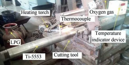
Fig.1. Experimental setup and heating process in machining of Ti-5553 alloy.
3. Result and discussion
3.1. Cutting and thrust force
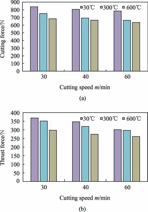
Fig. 2. Variation of cutting force (a) thrust force (b) at a feed rate of 0.1 mm/rev.
The forces were recorded at different cutting speeds,feed rates and workpiece temperatures at steady state condition.Fig.2(a)-(b)show the cutting and thrust forces recorded at different machining condition at 0.1 mm/rev feed rate. It was observed that there was 869N cutting force at room temperature when machining was conducted at 30 m/min cutting speed and 0.1 mm/rev feed rate.When heating was increased to 300°C, there was a reduction of 25% cutting force. However, increased to 600°C workpiece temperature, there was drastically 37% reduction in cutting force compared to 30°C.Again there was a reduction of 13%,14%,and 13%of cutting force at 30°C, 300°C, and 600°C temperature respectively, when cutting speed vary from 30 to 60 m/min. However,again increase in temperature; it was observed that there was no reduction of cutting force and some diffusion wear was observed.
Similarly,machining at a 0.15 mm/rev feed rate,the cutting and feed force increased in both room and elevated temperature machining condition compared to machining at a feed rate of 0.1 mm/rev. At high feed rate, heat dissipation from the cutting zone insufficiently results in more tool wear,hence high cutting and feed force [18] as shown in Fig. 3 (a)-(b).
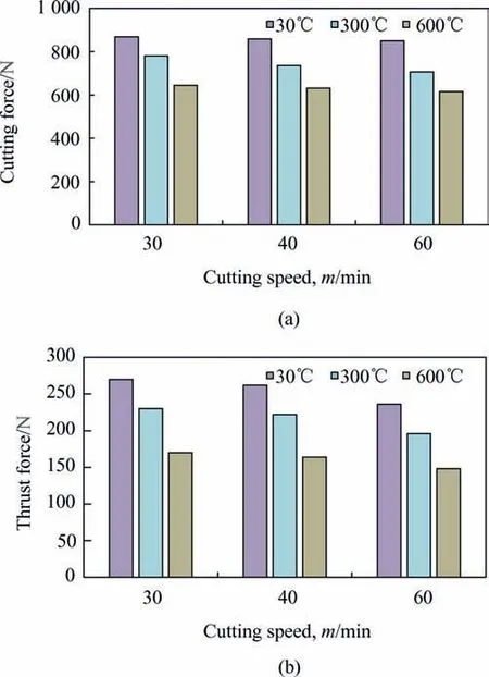
Fig. 3. Variation of cutting force (a) thrust force (b) at feed rate 0.15 mm/rev.
3.2. Tool wear
The flank wear in the interval of 5-7 min was taken during the machining operation. The criterion for tool failure for tungsten carbide tool was chosen 0.3 mm according to ISO measurement.Fig. 4 and Fig. 5 show the flank wear at a feed rate of 0.1 and 0.15 mm/rev cutting condition respectively.At room temperature,there was rapid tool wear, which failed within machining of 10 min,whereas an increase in heating temperature enhanced tool life up to 30 min. There was an increase in tool wear with the increase in feed rate, which supports the increase of cutting forces in both room temperature and elevated temperature machining condition.

Fig. 4. Flank wear at a feed rate of 0.1 mm/rev with different cutting speed and temperature.
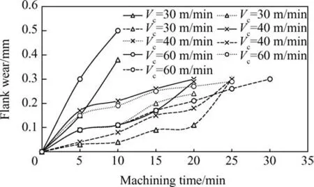
Fig. 5. Flank wear at a feed rate of 0.13 mm/rev with different cutting speed and temperature.
It is essential to study the wear mechanism during hot machining of the Ti-5553 alloy as it directly affects the machinability.From the observation adhesion,diffusion and build up edge formation in the cutting tool was observed. Fig. 6 shows the formation of tool wear at a cutting speed of 30 m/min,feed 0.1 mm/rev in different cutting conditions. In hot machining, not only workpiece is exposed to heat but also cutting tool.It was observed that at room and 300°C temperatures, there was adhesion wear type,whereas diffusion wear at 600°C workpiece temperature (Fig. 6).The abrasion tool wear at 30°C was may be due rubbing between the chip and tool,and less flowability of the chip over the rake face.Whereas at 600°C the friction between chip and tool is less and flow of chip is smooth.However,the increase chip temperature due to heating may evaporate some elements from the cutting tool and form crater wear (diffusion wear).
It was observed that the formation of crater wear in the cutting during hot machining was less when cutting speed increased from 30 m/min to 60 m/min due to the high flow of chip over the rake face of the cutting tool which reduce chip-tool contact time. So, it can conclude that hot machining at higher cutting has advantages over lower cutting speed. However, at 30 m/min, BUE (Built-up-Edge) was found at room temperature, which was verified with EDX (Energy dispersive X-ray) analysis (Fig. 7). Similar findings were observed by Refs. [1,7,9] in machining of the Ti-5553 alloy.
Ti (light grey) was found on the insert along the cutting edge.Along with titanium, aluminum in the rake surface of the cutting tool was found,but no evidence of carbon was also found.A similar type of observation was observed by Arrazola et al.[2]in machining of the Ti-5553 alloy.

Fig. 6. Formation of tool wear at cutting speed of 30 m/min, feed rate 0.1 mm/rev (a) 30°C (b) 300°C (c) 600°C.
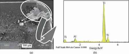
Fig. 7. Adhesion on the face of the cutting tool (a) Corresponding EDX (b).
4. Finite element modeling
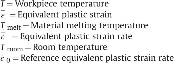
The hot machining simulation of Ti-5553 alloy has been done using the Deform-2D software. The workpiece was meshed with 8000 elements, whereas the tool was modeled as rigid. The workpiece and tool material properties were imported from the Deform inbuilt material library. The tool contact area meshed with high density because this area where high temperature and stress occurred during machining.Johnson-cook model has been used as shown in Eq.(1)and its material constants were also taken from the work[9].

Where σ =Flow stress of the materials.
A heat exchange window has been implemented to exchange heat locally on the surface and move along with cutting tool movement. Based on the requirement such as 30°C, 300°C, and 600°C respectively temperature was implemented on the workpiece using heat exchange window during the simulation[9,16,19].The thermal and displacement boundary condition of the workpiece and tool is shown in Fig. 8. The green line of the workpiece and cutting tool side represent at room temperature which is away from the cutting zone.The cutting area of the workpiece and tooltip was mesh with high mesh density because this area is mostly affected by temperature and stress on the tool as well as the workpiece [20].
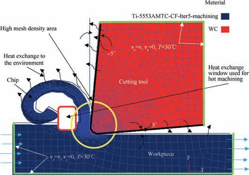
Fig. 8. Displacement and thermal boundary condition in hot machining.

Table 1Input parameters of FEM software.

Table 2Mechanical and thermal properties of Ti-5553 [4] and WC [24].
Simple shear friction model was used between the chip and cutting tool as expressed in Eq. (2)

Where,τ is the shear stress,m[0.4]is the shear friction factor and Kchipis the shear stress on the chip.
As Ti-5553 is low thermal conductivity material, for chip segmentation at higher cutting speed, Cockroft and Lantham fracture criterion have been implemented as in Eq. (3).

Where ε-is the effective strain,σ1is the maximum principal stress and D is the damage value.
For sensitivity analysis, the effect of three parameters such as mesh size,shear friction factor,and damage value has been studied by chip thickness and cutting force with the experimental result.The best agreement in cutting force, chip thickness was observed when shear friction factor 0.4 and damage value of 250. No sensitivity analysis has been done for a hot machining process;the same value has been implemented.
The simulation was carried out at different cutting condition for calculating cutting and thrust force. The input parameters used in FEM simulation is mentioned in Table 1.
The cutting and feed force were extracted in steady state condition. The reduction of cutting and feed force was observed with the increase of heating temperature. The reduction of forces at higher temperature was due to the rise in cutting zone temperature which soften the workpiece material. At room temperature, the maximum cutting zone temperature was 856°C, whereas, at 300°C, the process zone temperature increased to 963°C. Again increase the workpiece temperature 600°C, the process zone temperature increased to 975°C as shown in Fig. 9.
The increased of process zone temperature reduced the flow stress of the Ti-5553 from 1600 MPa at room temperature to 1320 MPa at 600°C.
It was also observed that reduction of flow stress also reduced tool temperature due to thermal softening of the workpiece at hot condition.Fig.10d show the tool temperature at room temperature was around 508°C whereas at 600°C the tool temperature reduced to 452°C. A similar observation was observed in machining of Inconel 718 using flame heating [21]. The reduction of forces reduced the apparent friction coefficient between the chip and tool as expressed in Eq. (4).

Where μ=coefficient of friction, Fcis the cutting force, Ftthrust force and α is the orthogonal rake angle.
The highest chip temperature was observed at 600°C. Fig. 11 show the simulation cutting force at Vc=40 m/min, f=0.1 mm/rev for room and different elevated temperatures. The simulated cutting force was fluctuating in nature at room temperature which indicates there is sawtooth chip formation whereas at 600°C there is the smooth force which indication of continuous chip formation.
Chip analysis was also carried out using an optical microscope.The chips were collected after each machining condition, polished with different grade of sand papers and its thickness was measured using a optical microscope.The chip thickness value decreased with the increase of workpiece temperature which verifies that the shear angle increased with the increase of heating temperature compared to room temperature [19]. In-room temperature, there was the sawtooth type of chip formation, which results in the fluctuation of cutting force, whereas, with the increase of heating temperature, the frequency of serration decreased which confirmed that formation of the continuous chip as shown in Fig. 12. Increased feed rate from 0.1 mm/rev to 0.15 mm/rev increase the serration in the chip in the experimental chip.However,there was no such phenomenon occurs in numerical simulation.The application of heat reduced the chip pitch distance which allows segment chip into the continuous chip as studied in laserassisted machining of Ti-5553 alloy [3] and flame heat machining of Inconel 718[22,23].Fig.13 shows that less than 5%error between the simulated and experimental results in all machining conditions.
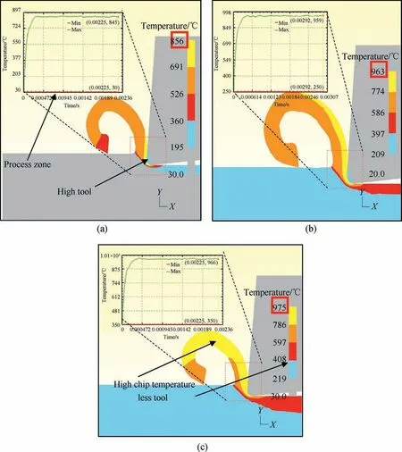
Fig. 9. Cutting zone temperature (a) room temperature (b) 300°C (c) 600°C at cutting speed of 30 m/min and feed rate 0.1 mm/rev.

Fig.10. Effect of workpiece temperature on flow stress at primary shear deformation zone(a)30°C(b)300°C(c)600°C(d)tool temperature at 30°C(e)tool temperature at 600°C during simulation at Vc=30 m/min and f=0.1 mm/rev.
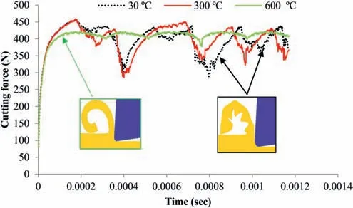
Fig.11. Simulated cutting forces during machining Ti-5553 alloy at the higher cutting speed of 60 m/min.
5. Conclusions
Flame heating has been used as a heating source during machining of near titanium alloy, i.e., Ti-5553 alloy. The machinability performance of Ti-5553 was observed at two heating temperature along with room temperature. A FEM has been used to study the effect of workpiece temperature on cutting force, thrust force, flow stress and cutting zone temperature at an elevated temperature in the hot turning of Ti-5553.
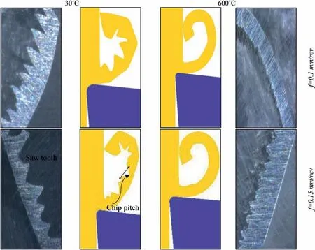
Fig.12. Analysis of chip formation between simulated and experimental for different workpiece temperatures and feed rates at cutting speed of 60 m/min.
The application of heating reduces the forces compared to room temperature machining. This is due to the reduction of flow stress of the workpiece because of the application of heating. Adhesion wear was the primary tool wear mechanism when machining of the Ti-5553 alloy at the dry cutting condition, whereas diffusion wear was the dominant tool wear mechanism during heating condition.The chip pitch distance decreased in hot machining which indicates that the segmented chip became a continuous type.The formation of continuous chip indicates that there is smooth force compared to fluctuating force generated during room temperature machining condition. Experimental work has been carried out to validate the simulated result, and good agreement has observed.
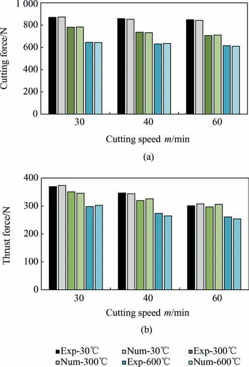
Fig.13. Experimental and simulated (a) cutting force (b) thrust force at a feed rate of 0.1 mm/rev in different workpiece temperature.
杂志排行
Defence Technology的其它文章
- Body armour - New materials, new systems Ian G. Crouch*
- Special materials in pyrotechnics VII: Pyrotechnics used in thermal batteries☆
- Real-time calculation of fragment velocity for cylindrical warheads
- Heavy metal free primers: Polymorphism of gadolinium and titanium in the context of GSR glass phase Felice Nunziata
- Mitigation of EDFA transient effects in variable duty cycle pulsed signals
- Ballistic impact properties of woven bamboo- woven E-glassunsaturated polyester hybrid composites
