Special materials in pyrotechnics VII: Pyrotechnics used in thermal batteries☆
2019-07-16ErnstChristianKoch
Ernst-Christian Koch
Lutradyn Energetic Materials Science & Technology, 67661, Kaiserslautern, Germany
Keywords:Barium chromate Heat-powder Iron Lithium Molten salt Potassium perchlorate Pyrotechnics Thermal battery Zirconium
A B S T R A C T Thermal batteries are unique direct current (DC) electrical power sources with long shelf live, high reliability and higher power density than classical alkaline batteries. This paper gives a brief overview into the working principle of thermal batteries and reviews the properties of zirconium/barium chromate(Zr/BaCrO4) pyrolant previously used as first fire and iron/potassium perchlorate (Fe/KClO4) pyrolant(Heat), commonly applied as heating pellet in thermal batteries and its hazard properties. The review gives 64 references to the public domain.CAS-Nos.Zr:[7440-67-7],BaCrO4:[10294-40-3],Fe:[7439-89-6], KClO4: [7778-74-7], Viton: [9011-17-0].
1. Introduction and general design of thermal batteries
Thermal batteries, also known as thermally activated batteries,thermal reserve batteries or molten salt batteries work in a similar way as regular alkaline batteries however,they contain a solid ionic as an electrolyte which does not conduct electricity at ambient temperature and hence the battery does not undergo any kind of deterioration and can have shelf lives in excess of 25 years. To become activated these batteries require heat input to liquefy the electrolyte and become electrically conductive.Due to the very high electrical conductivity of molten salts thermal batteries provide higher power densities than classical batteries. Fig. 1 compares a thermal battery cell(LixSiy/FeS2)with ambient temperature battery systems Zn/AgO and Li/CF. Both long shelf life and high-power density make thermal batteries ideal choice for ordnance systems such as missiles and guided munitions,however they are also high price items with limited energy density.
Fig. 2 schematically depicts a typical thermal battery and its components [3]. The cell assembly comprises an anode, the separator with the immobilized electrolyte mixture, the cathode and a pyrotechnic heating pellet. Depending on the cell voltage the battery typically contains a stack of several cells. While older battery designs comprise an external lateral pyrotechnic ignition (fuse strip)triggered by an electric match nowadays more commonly an electrical igniter fires down the central cavity of the cell stack to ignite the pyrotechnic pellets[4].This assembly is rigidly wrapped in multiple layers of thermal insulation and firmly encased in an airtight stainless-steel cylinder which bears glass-sealed electrical output terminals and terminals for the electrical igniter.
1.1. Anode material
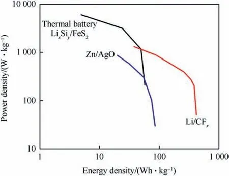
Fig.1. Comparison of power and energy density of thermal battery cell with common ambient temperature cells.
Lithium is the element of choice for the anode in electrochemical applications due to its superior electrochemical potential(Li/Li+:- 3.04V) and its high specific Coulombic capacity, due to its low atomic weight and low density (ρ=0.534 g cm-3). However,for practical reasons - as pure lithium has too low a melting point(mp: 180°C) - compounds such as, LiAl (mp: 700°C), Li13Si4(mp:722°C), Li7Si3(mp: 752°C) are used as anode materialism also Lirich borides also been explored as alternatives to both LiAl and Li13Si4[6,7].Another common anode material is calcium which has a lower electrochemical potential than lithium but which also bears a higher melting point(mp:845°C).Typical anodes in batteries are not made from pure lithium but comprise about 2/3 of high melting lithium alloy, immobilized with 2/9 sponge iron powder and 1/9 electrolyte premix, the latter containing up to 35 wt% MgO as porous binder.
1.2. Cathode
Typical cathode material in thermally activated batteries is iron(II)sulfide(FeS2)bearing the S2-2anion.A general advantage of FeS2is its insolubility in molten alkali halide eutectics.Therefore it cannot diffuse to the anode and cause short circuiting[8].

On the flipside,FeS2decomposes at temperatures around 450°C according to Eq. (1) [9,10].and is a semiconductor in this temperature regime. Hence, cobalt(II) sulfide (CoS2) is used to a greater extent in recent years in thermal batteries[11].Though CoS2is more expensive than FeS2it has a favourably higher decomposition temperature of ~650°C(see Fig. 3) and exhibits near metal type conductivity at elevated temperatures [12] (Table 1).
The reactions upon discharge can be summarized by the following Eqs.(2)-(5).In case of cobalt(II)disulfide as the cathode material a similar sequence is understood to occur [10].
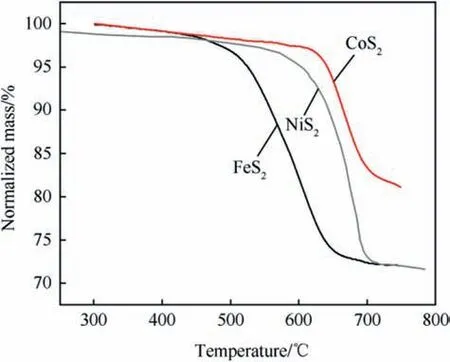
Fig. 3. Thermal decomposition of FeS2 NiS2 and CoS2 after Ref. [12].
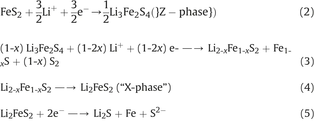
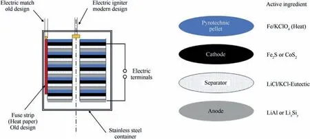
Fig. 2. Schematic Cut-away drawing of a thermal battery after Ref. [5].

Table 1Sulfide materials for cathode applications [13].
Similarly, as for the anode the cathode is not pure sulfide material but contains electrolyte and porous MgO as both binder and wetting agent to improve interaction between the electrolyte and the cathode.
Another material investigated for thermal batteries is NiS2which possesses an intermediate decomposition temperature but similar to FeS2is a semiconductor too at high temperatures [14].Table 1 displays important properties of sulfides used as cathode materials.
1.3. Electrolytes
Typical electrolytes used in molten salt batteries are binary and ternary eutectics from alkali halide salts such as LiCl-KCl (mp:352°C) or LiF-LiCl-LiBr (mp: 445°C) [15]. With the binary electrolyte precipitation of LiK6Fe24S26Cl phase due to reaction of iron(IV)sulfide with potassium chloride melt has been observed [16]. For mechanical stabilization of the molten electrolyte against spin,and acceleration forces(upon function)it is blended with a binder such as porous MgO that contains the molten electrolyte by capillary forces. Typically, electrolytes comprise between 30 wt% - 35 wt%MgO as binder [11]. Table 2 shows the conductivity, κ, of various molten salts in comparison with aqueous ionic solutions.
The composition of typical thermal batteries and their performance characteristics are given in Table 3.
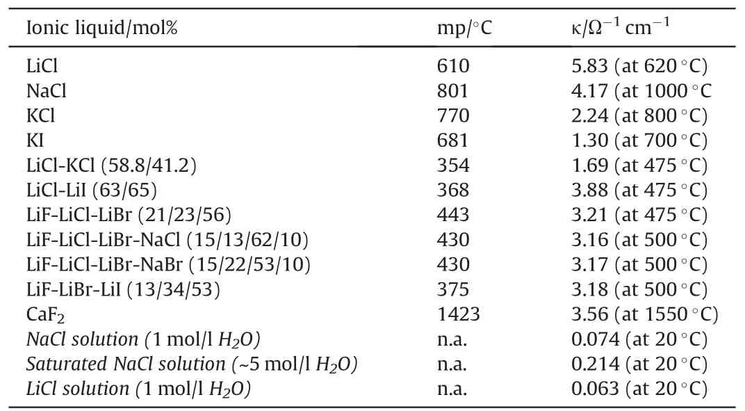
Table 2Electrical Conductivities of various ionic liquids [5,8,11,17,18].
1.4. Thermal activation & discharge
The first thermal battery was invented by German Georg Otto Erb in the 1940s and found mass use as a fuse battery in the A4 ballistic missile.This battery-based on calcium/calcium chromate- did not require a pyrotechnic heating charge but harvested the excess thermal energy provided by the rocket engine[19].Similarly,thermally activated cells bearing no pyrotechnics are in continuous use in borehole applications where high temperatures are encountered. Apart from these applications the use of thermal batteries in most missiles and projectiles requires an autonomous heat source that can be triggered.
To activate thermal batteries pyrotechnic heating pellets are required which are integrated regularly in the stack of cells as is depicted in Fig.1. Upon ignition the heat released causes the electrolyte to liquefy and the battery starts operating.
In order to function in the desired way these pyrotechnics have to satisfy a number of requirements, these are:
· No or at least very little permanent gaseous products formation upon combustion to avoid pressurization of the cell.
· Upon combustion the composition must maintain its physical shape and should not melt at any stage.
· The reacted compacted pellet must be a good electrical conductor.
· The reaction should not release excessive heat to avoid destruction of either anode or cathode.
· The reaction should initiate and proceed very rapidly.
· The reaction products should not cause any detrimental reaction with either anode or cathode.
Reviews on thermal batteries and on various pyrotechnics,have been written by Sheptunov [20] Almada et al. [21], Mosier-Boss et al. [22] and Guidotti & Masset[3,7,10,12,15].
2. Pyrotechnic compositions
2.1. Igniter composition - zirconium/barium chromate - pyrolant and heat paper
A pyrotechnic system originally used as pyrotechnic pellet in thermal batteries is the so-called “Heat paper”. Heat paper is a glass-fibre substrate impregnated with a pyrolant based on Zr/BaCrO4and an inorganic silicate binder[23].For impregnation the glass fiber mat (which is of a thickness in the order of 0.30-0.35 mm) is guided through an applicator that is filled with an aqueous slurry containing the pyrolant mix Zr/BaCrO4and alkaline aluminium silicate, (AlO)2SiO3the latter which serves as binder. After wiping off surplus pyrolant slurry the impregnated tape enters a thermal dryer and is wound up. The heat paper pyrolant composition typically ranges around 20 ± 2 wt% zirconium. The calorific content is ~1740 ± 20 J⋅g-1with a burn rate of~160 mm s-1.

Table 3Typical materials used in thermal battery systems [5,8,11].
Modifications of this material have become known as Z-2 or Z-3.A composition using ZrNi alloy instead of Zr is termed T-2[24].Heat paper based on Zr/BaCrO4is sensitive to impact and extremely sensitive to electrostatic discharge which makes handling of this highly dangerous. On top chromium(VI) compounds are objectionable components and as such formulations based on them have to be replaced. The calorific output of Zr/BaCrO4heat paper upon ageing through hot storage drops significantly when exposed to temperature equal and excess of 150°C. Similarly, the burn rate of heat paper drops for the same conditions[25].Heat paper is still in use as a pyrotechnic first fire in some battery designs, however,given its high content in objectionable barium chromate(VI) replacements are sought for the latter which could include molybdates[26] or tungstates [27] of alkaline earth metals.
2.1.1. Thermochemistry of Zr/BaCrO4
The enthalpy of explosion for a series of binary Zr/BaCrO4pyrolants has been determined experimentally by Ellern and is reproduced below in Table 4 both per unit mass and unit volume[24]. Those values are compared in Fig. 4 with the calculated adiabatic combustion temperature indicating that the equilibria established with thermochemical codes do not quite describe the actual chemistry.
The Zr/BaCrO4(22/78) pyrolant is not very sensitive to thermal stimuli and has a very high differential thermal analysis (DTA)onset temperature of ~896K(623°C)at 40K min heating rate under argon flow(150 ml min-1) (Fig. 6) [29]. However, the electrostatic

Table 4Enthalpy of Combustion of binary Zr/BaCrO4 mixtures,after Ref. [24].
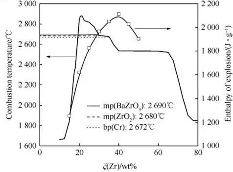
Fig.4. Calculated adiabatic combustion temperature with EKVI[28]and experimental enthalpy of explosion [24] of Zr/BaCrO4 as function of stoichiometry.
discharge 50% initiation energy for a Zr/BaCrO4(20/80) based on 8.4 μm Zr particles and 0.4 μm barium chromate is only 100 μJ and thus is highly sensitive to electrostatic stimuli [30]. The electrostatic sensitivity for coated Zr pyrolant is much higher than for a pyrolant that bears a coating on the barium chromate only. The burn rate of Zr/BaCrO4pyrolant with Viton and without has been investigated by Berger [31] and Kuwahara et al. [32]. The binary system exhibits its highest burn rate at ξ(Zr)~57 wt%.The pyrolant containing 1 wt%Viton show a maximum burn rate,u=22 mm s-1,at ξ(Zr)=40 wt%. At high Viton content (10 wt%) the burn rate further drops significantly and has a maximum at around 55 wt%Zr(u=9 mm s-1(see Fig. 5).
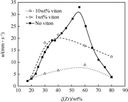
Fig. 5. Burn rate of Zr/BaCrO4 and Zr/BaCrO4/Viton after Ref. [31,32].
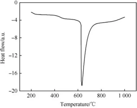
Fig.6. DTA of Zr/BaCrO4(20/80)under Argon and at 40 K min-1 heating rate,after ref.[29].
Separately coating Zr, BaCrO4or both components with 1 wt%Viton binder reveals that coating of Zr with Viton enhances the combustion rate whereas coating the barium chromate slows down the burn rate. However, these effects become indistinguishable at mass fractions >10 wt% Viton. Lead-tube burn rates for Zr/BaCrO4with 2 wt%nitrocellulose binder have been determined in Ref.[33].
The DTA of Zr/BaCrO4exhibits a very high onset temperature of 623°C, however the presence of Viton lowers the thermal onset.Although determined at lower heating rate (20°C⋅min-1) and at higher ξ(Zr)the onset shifts down by ~170°C-452°C as is depicted in Fig. 7.
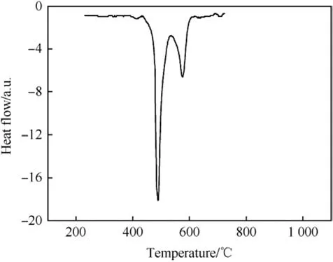
Fig. 7. DSC of Zr/BaCrO4/Viton (57/38/5) under Argon at 20K⋅min-1 heating rate after Ref. [30].
Other than in thermal batteries “Heat paper” has been used as first fire in decoy flares[34].
2.2. Pyrotechnic heater-iron/potassium perchlorate(IPP)-“Heat”pellets
In the early 1960s United States Department of Energy (DOE)and Department of Defense (DOD) sought a replacement for the highly sensitive “Heat paper”. Contracts were put out and it was found that fuel rich pyrolants based on spongy iron powder and very fine potassium perchlorate(15 μm)fulfil the above-mentioned requirements. A very detailed history of the development of Fe/KClO4is given by Guidotti in Ref. [25].
Although the use of iron powder in pyrotechnics may be counterintuitive as we are familiar with the quick oxidation(rusting)of unprotected iron powder at ambient humidity,handling of fine iron powder at reduced humidity (≤3% RH at 20°C) is technically feasible.
2.2.1. Thermochemistry
The enthalpy of reaction of Fe/KClO4as function of the stoichiometry in the range between 80 wt%-90 wt%Fe correlates linearly with the iron content and is given in Table 5.The experimental data have been obtained with NX-1000 iron powder which is described further down below.
Eq. (6) depicts the idealized combustion reaction of a typical pyrolant used in standard thermal batteries having a weight ratio of 88/12 iron/potassium perchlorate.
The calculated equilibrium combustion temperature of this composition equals 1409K at 0.1 MPa which is still below the vaporization temperature of KCl.
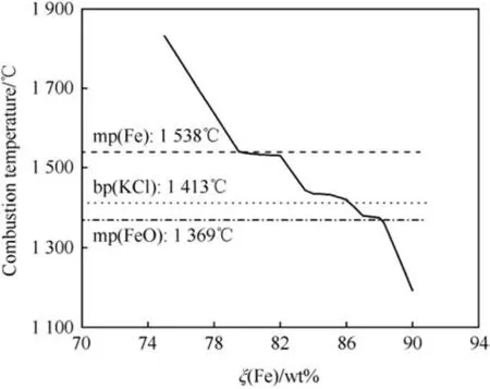
Fig. 8. Adiabatic Combustion temperature of Fe/KClO4 calculated with EKVI [28].
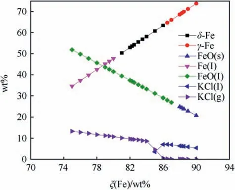
Fig. 9. Equilibrium composition of Fe/KClO4 calculated with EKVI [28].
Fig.8 shows the adiabatic combustion temperature of Fe/KClO4for ξ(Fe) ranging between 75 wt% - 90 wt% superimposed on the fusion points of both Fe, FeO and the boiling point of KCl limiting the temperature and thereby causing the local flattening of the curve at the corresponding temperatures. The calculated equilibrium composition at Tcis depicted in Fig.9 whereas Fig.10 depicts the calculated composition of the combustion products at ambient temperature.
While calculations predict Fe and Fe3O4to be main combustion product [28] experimental analysis with transmission electron micrography and energy dispersive X-ray analysis (EDX) reveals that unreacted iron particles are covered with a thin (d ~200 nm)FeO-shell [37].
As a thermal battery must withstand rough environmental conditions such as shock, impact, spin and extreme acceleration,heat pellets must not disintegrate upon these stimuli. Hence high mechanical strength is required. To achieve this high mechanical integrity Heat pellet-composition requires a sponge-type iron powder which allows for a good interlocking of the granules.Fig.11 depicts electron micrographs of increasing resolution(left to right)of a sponge type iron designated NX-1000 manufactured by Ametek. The images show the particular branching of the particles which explains for the outstanding mechanical properties of pellets based on this material. The properties of NX-1000 are given in Table 6.
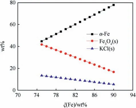
Fig. 10. Ambient temperature composition of Fe/KClO4 combustion products calculated with EKVI [28].
A process for producing iron powders with suitable morphologies for use in heat pellets has been disclosed in Ref. [38].
Heat pellets are typically consolidated to densities higher than 2.75 g cm-3as mechanical strength at lower densities is insufficient. The influence of pellet density on breaking strength of 2.5g test pellets is given in Table 7. The density pressing pressure relationship for two pyrolants is depicted in Fig.12.
The particle size of the potassium perchlorate used in heat powders affects both burn rate and ignitability of the pellets.Fig.13 shows the evolution of both parameters. The burn rate increases with increasing KClO4-particle size which is a characteristic for many metal/oxidizer pyrolant systems where the metal melting temperature is well above the decomposition temperature of the oxidizer. The ignition energy surprisingly increases in the same range with increasing particle size as well. The burn rate of Fe/KClO4is determined in a set-up that mimics the configuration in the final battery and is shown in Fig.14.
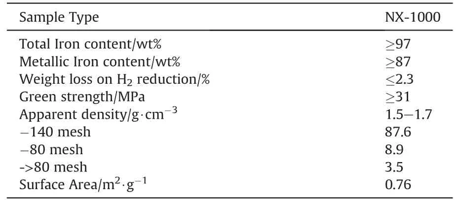
Table 6Properties of NX-1000 iron powder after Ref. [38].
As is evident from Fig.15 the burn rate decreases as the theoretical density is approached and pellets having densities higher than 4-5g⋅cm-3cannot be properly ignited and do not sustain combustion.
Thus,it appears that some porosity is required to allow for both ignition and propagation of combustion.
The influence of density on the burn rate of various Fe/KClO4pyrolant pellets as 31.75 mm diameter pellets has been investigated by Guidotti [36,40]. At ξ(Fe)=80 wt% a maximum burn rate of u=550 mm s-1is obtained at low density (55% TMD), whereas consolidation of the same pyrolant composition to 80%TMD yields a reduction of the burn rate by more than 50% (u=202 mm s-1).For the pyrolants containing 82 wt%and more iron the influence of density is less pronounced as is depicted in Fig.16.
Lead tube burn rates of various Fe/KClO4mixtures using different iron powders have been investigated by Callaway et al.[41].Fig.17 shows the burn rate as function of the stoichiometry for three different iron powders whose characteristics are compared in Table 8.
Heat pyrolant stemmed into lead tubes yields much lower burn rates as those consolidated to pellets. Obviously, the lead tubing(λPb=35W/(m⋅K)) effects dissipation of heat and slows down the burn rate.A pyrolant using a multimodal spherical iron powder(see Fig. 18) yields burn rates in excess of 50% of those based on NX-1000.

Fig.11. Electron micrographs of NX-1000 sponge iron manufactured by Ametek.

Table 7Effect of pellet density on breaking strength for (88/12 Fe/KClO4)from Ref. [35].
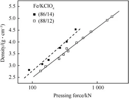
Fig.12. Effect of consolidation Force on density after Ref. [39].
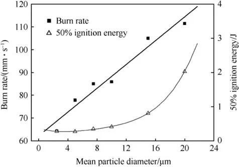
Fig.13. Effect of KClO4 particle size of burn rate and ignition energy for 88/12 IPP after Ref. [35].
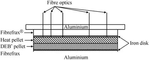
Fig.14. Burn rate measurement setup. *DEB = Depolarizer(CaCrO4), Electrolyte (LiCl-KCl), Binder (SiO2).
The burn rate of Heat (84/16) prepared from a Fe powder obtained by spray pyrolysis at different temperatures increases with the pyrolysis temperature as is indicated in Table 9 [42].
2.2.2. Thermal studies & stability
Callaway et al. studied the reaction of (80/20) Heat powder in the DSC under air at 10 K min-1heating rate. Fig. 19 show DSCtraces for both powdered and pelletized material. The pelletized material shows a distinct pre-ignition reaction directly after the KClO4-phase-transition at 299°C and a steep onset of the main oxidation reaction at 480°C. At 772°C the melt endotherm for potassium chloride is observed.
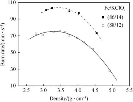
Fig.15. Influence of density on Burn rate of Two Heat pyrolants after Ref. [19].
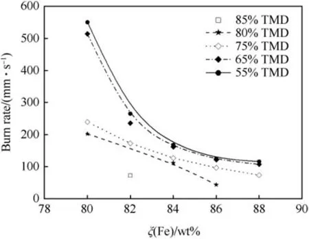
Fig.16. Influence of density on Burn rate of Heat pyrolants after Ref. [36,40].
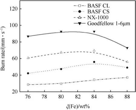
Fig. 17. Lead tube burn rate measurement of Heat powders based on various iron qualities after Ref. [41].

Table 8Properties of iron powders studied in Ref. [41].
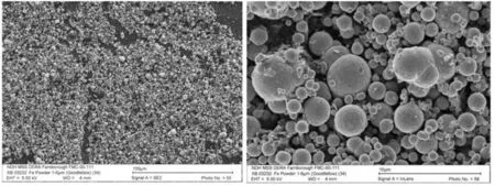
Fig.18. Electron micrographs of Goodfellow iron powder as quoted by Callaway et al. courtesy of International Pyrotechnics Society [41].

Table 9Burn rate of consolidated Heat 84/16 as function of pyrolysis temperature[42].

Fig.19. DSC studies of Fe/KClO4 (80/20) by Callaway et al. after Ref. [41].

Table 10Kinetic parameters for (Fe/KClO4)Heat powder[43].
Kinetic data for Heat pellets (Fe: 44 μm, 99.9%; KClO4: 10 μm,99.9%)has been determined by Alkan et al.[43].Table 10 shows the activation energy and preexponential factor for a range of formulations which is about in the same ballpark and which also reflects the observation by Reinholz et al.[44]that ignition energy of Heat does not vary appreciably with stoichiometry in the considered range.
Exposure of Fe/KClO4(88/12) heat pellets to humidity levels equal and greater than 33%RH affects calorific output, ignition energy and burn rate as is depicted in Table 11. Also, hot storage under dry conditions affects burn rate and ignitability [25].
23% RH does neither affect calorific output nor ignitability.However, exposure to 33% RH and humidity above yield both reduction in calorific output and frequent ignition failures[25,44]. The ignition of Heat pellets in an Argon filled shock tube has been investigated by Evans [45]. Gillard et al. studied the Laser-ignition of Heat pellets [46]. Koyuncu et al. have developeda model to describe the combustion of Heat pellets and the temperature evolution of thermal battery stacks comprising them [47].

Table 11Influence of storage conditions on ignition and calorific output.
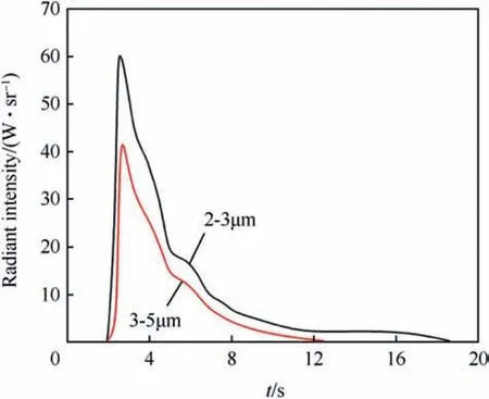
Fig.20. Radiometric profile of single 60 mm diameter Heat(86/14)pellet in still air at ambient pressure.
Heat powders containing other iron powder qualities than NX-1000 have been investigated in great detail by Czajka & Wachowski et al. [48-52]. The same authors also studied the effect of catalytic amounts of iron oxides present on the surface of iron powder on the decomposition of KClO4[53].
2.2.3. Other uses
Heat Pellets have been proposed as blackbody emitters for use in infrared decoy flares by Callaway [54]. Fig. 20 shows the radiometric profile for a 60 mm diameter disc in 2-3 μm and 3-5 μmband. Unlike typical pyrotechnic flares the combustion of those pellets yields very little smoke(mainly infrared-transparent KCl(s))which effects unobscured emission of infrared radiation.
3. Hazards
As thermal batteries contain both energetic (Heat) and combustible materials (Li-alloys) they are often classified under Hazard Division HD1.4S [55]. The general hazards encountered with thermal batteries are the high container temperatures encountered upon firing and the resulting danger of fire for flammable materials adjacent to it.The hazards of bulk amounts of heat powder (84/16) have been investigated by Guidotti et al. [56]. Unexpected ignition of large bulk(3.6 kg)heat powder produces large fires which can have disastrous outcome.The loose material shows rapid ignition (<100 ms) and yields temperatures in excess of 1200°C. The issues relating to the disposal of thermal batteries have been addressed in Refs. [57,58] respectively.
No information is available in the public domain on the response of thermal batteries to Insensitive Munitions Test [59].
4. Outlook
Leventis et al. [60] have prepared iron(0) aerogels infiltrated with KClO4which show an inherent high degree of porosity and exhibit extreme high combustion rate.Replacement of perchlorates is considered in some countries a necessary step and hence other alternative halogen-free oxidizers are sought. Potential candidates include transition metallates [26,27] including potassium ferrate(VI)K2[FeO4]the latter which has been investigated in detail by Pliskin et al.[61,62].Poret et al.have proposed to use Ni/Al multireactive layers commercially known as Nanofoil®to heat thermal batteries [63] likewise other intermetallic systems have been considered as potential replacement for Heat [64].
5. Summary
State of the art thermally activated batteries use an alkali halide eutectic mixture that serves as electrolyte. The anode of thermal batteries is based on high melting alloys of lithium, the cathode uses either iron disulfide or cobalt disulfide which in comparison to the former allows for higher operating temperatures. To trigger a thermal battery a stack of pyrotechnic heating pellets is ignited that upon combustion develops sufficient heat to liquify the electrolyte.Those heating pellets are commonly composed from a dendritic iron powder and potassium perchlorate with iron contents in the 84 wt%-86 wt% ballpark.
Acknowledgement
The author thanks the referees for pointing out errors and inconsistencies and for sharing valuable information on cathode reaction.
杂志排行
Defence Technology的其它文章
- Body armour - New materials, new systems Ian G. Crouch*
- Real-time calculation of fragment velocity for cylindrical warheads
- Heavy metal free primers: Polymorphism of gadolinium and titanium in the context of GSR glass phase Felice Nunziata
- Mitigation of EDFA transient effects in variable duty cycle pulsed signals
- Ballistic impact properties of woven bamboo- woven E-glassunsaturated polyester hybrid composites
- Experimental investigations on wear properties of Palm kernel reinforced composites for brake pad applications
