Optimization of Dividing Wall Column with Heat Transfer Process Across the Wall for Feed Properties Variation
2019-07-15HuYuqiLiChunli
Hu Yuqi; Li Chunli
(National-Local Joint Engineering Laboratory for Energy Conservation of Chemical Process Integration and Resources Utilization, School of Chemical Engineering and Technology,Hebei University of Technology, Tianjin 300130)
Abstract: This paper investigates the thermal-coupled effect across the wall and the optimal heat transfer region of the wall for enhancing the energy saving effect of dividing wall column (DWC), and also studies the effects of feed thermal condition (q) and middle component composition of feed (cB) on the heat transfer process, the optimal heat transfer region,and the maximum heat transfer quantity across the wall. The simulation results show that the maximum heat transfer quantity across the wall and the potential for energy saving increase with the increase of q, while with the limitation of temperature difference across the wall, the beneficial heat transfer effect between certain range of stages, which are involved in the optimal heat transfer region, cannot be realized completely for a specific value of q. Besides, compared with q, a changing cB does not change the degree of realizing the beneficial heat transfer effect, but can bring about the variation of liquid split ratio (RL) and vapor split ratio (Rv). Thus, for achieving a maximum energy-saving effect of DWC, different q and cB need to find its own corresponding suitable heat transfer process across the wall.
Key words: dividing wall column; heat transfer process; thermal-coupled effect; feed properties
1 Introduction
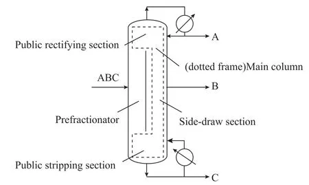
As a typical method to solve the problem of high energy consumption and low thermodynamic efficiency in petroleum and chemical fields, the thermal-coupled technology was proposed by Petlyuk[1]in 1965. The dividing wall column (DWC, Figure 1) as one of forms for realizing the thermal-coupled technology has been attracting the attention of many engineering experts. The characteristic structure of DWC is the dividing wall installed in a single column shell, which divides the column into four parts,viz.: the public rectifying section, the prefractionator, the side-draw section, and the public stripping section. For the convenience of research, the experts define the sum of the public rectifying section, the side-draw section, and the public stripping section as the main column[2]. In this special device, different components have its own transmission paths that make the mixture components (ABC,A as the light component, B as the middle component, C as the heavy component) primarily divide into AB and BC and achieve a sharp separation between A and C, in order to achieve an approximately even distribution of B in prefractionator, and make the overhead stream (AB)and the bottom stream (BC), which come from the prefractionator, continuously separated in the main column.Compared with the conventional distillation sequence in which A, B, C are competitively separated in first columns (since the distillation sequence generally includes two or three columns.), there are only two components in every section demarcated by the feed location and the side-draw location in DWC, which can avoid remixing phenomenon brought about by competitive relationship of three components in the simultaneous separation process,reduce the exergy loss produced by that phenomenon, and save 10%—60% of energy and 10%—50% of equipment investment[2]. DWC has great research value and application prospect.
So far the heat transfer process across the dividing wall (namely the heat transfer process between the prefractionator and the side-draw section) was ignored in most of researches[3-10]. In fact, unless the dividing wall is made by thermal insulating material, there exists a temperature difference and an inevitable heat transfer process between two sides of the wall. Lestak[11]pointed out the change of heat transfer quantity within 3% can bring in a change of energy consumption of DWC within 10%,Halvorsen[12]also showed the direction for optimization of operating points and energy consumption changes with different heat transfer processes across the wall. Ignoring heat transfer process will in fluence the static simulation and the dynamic control in subsequent application. The earlier research work[13]showed that the heat transfer process and the adiabatic process occurring in different areas of dividing wall have various influence degree toward the energy saving effect. This paper investigates the thermalcoupled effect and the optimal heat transfer region between the prefractionator and the side-draw section. Based on this effect and the method of attaining the optimal heat transfer region, the effect of feed properties on heat transfer process across the wall is analyzed, and in order to achieve a maximum energy-saving effect, the corresponding optimal heat transfer processes for different feed conditions are presented, which provides the research foundation to achieve the industrial design and application.
2 Optimal heat transfer region across the wall
For convenience of simulating by Aspen Plus, the real model of DWC in which the heat transferred across the wall is equivalently transformed into the four columns model in which the virtual intermediate heat exchangers are combined, and the coupled vapor streams and liquid streams in the DWC model are equivalently converted to that between different sections of four columns model (Figure 2).i.e., when the heat transferred across the wall is changed to that between the virtual intermediate heat exchangers,if the external cryogen or external heat source required by virtual intermediate heat exchangers for one side of the wall(prefractionator or side-draw section) can be supplied by different types of virtual intermediate heat exchangers of the other side of the wall (side-draw section or prefractionator),the thermal-coupled effect across the wall is formed. Which type of the virtual intermediate heat exchangers needs to be installed for each stage of prefractionator and side-draw section is decided by the grand composite curve (CGCC).CGCC can be used to identify the feasibility of adding intermediate heat exchangers and indirectly justify whether the exergy loss can be reduced and the potential of energy saving of DWC can be enhanced.
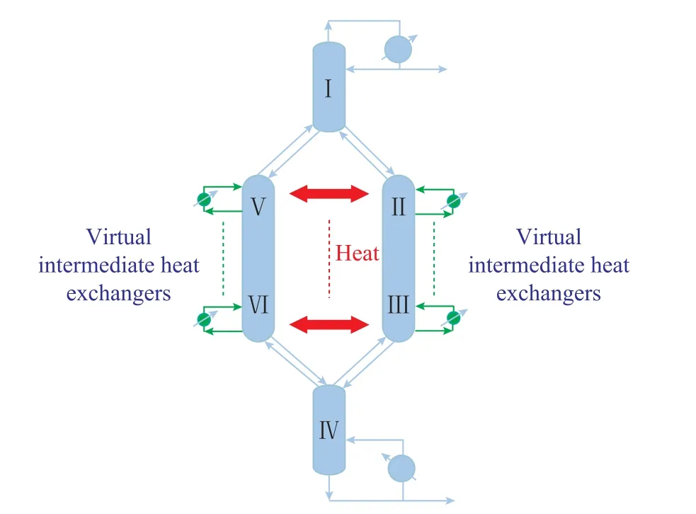
Figure 2 Four columns model
The previous research has proved that the demarcation point between the virtual heat source section and the virtual heat sink section appears on the stage which has a minimum enthalpy value[13]. For the sake of energy saving and thermal efficiency improvement, the virtual intermediate condenser can be added above the demarcation point, and the virtual intermediate reboiler can be added below the demarcation point. If one stage on one side of the wall is provided with a virtual intermediate condenser, and its corresponding stage, which is located at the same position as the former one on the other side of the wall, is provided with a virtual intermediate reboiler,the beneficial heat transfer effect between them can be utilized. The optimal heat transfer region across the wall(namely the beneficial heat transfer region) can be set.On the contrary, if two stages at the same position of two sides of the wall are provided with the same type of virtual intermediate heat exchangers, the heat transfer process between them is not beneficial, which should be avoided.
3 Instance Analysis
3.1 Simulation conditions
In this paper, a separation task is taken as an example:The mixture components serving as the saturated liquid feed, which consists ofn-hexane,n-heptane, andn-octane with a corresponding feed molar ratio of 0.25, 0.5, and 0.25, respectively, are subject to fractionation at a feed flowrate of 100 mol/h, and the products should have a purity equating to a mole composition of 0.98 apiece(which means that the mole composition ofn-hexane in the overhead product is 0.98, the mole composition ofn-heptane in the side-draw product is 0.98, and the mole composition ofn-octane in the bottom product is also 0.98).Based on these conditions, some rigorous simulations and optimizations are worked out for minimizing the reboiler heat duty of DWC coupled with the adiabatic process across the wall, with the results presented in Table 1.
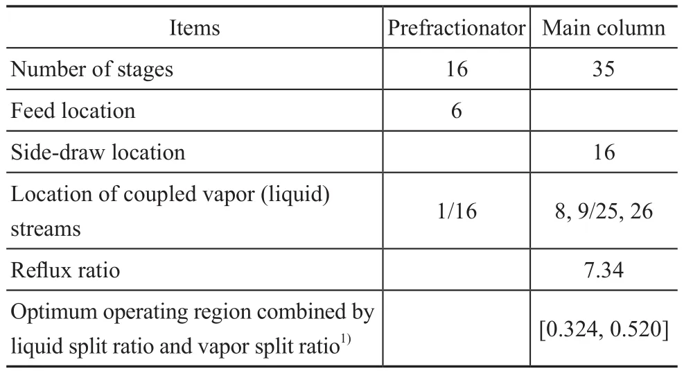
Table 1 Rigorous optimization details of DWC with adiabatic process across the wall
3.2 Effect of feed thermal condition on heat transfer process across the wall
Figure 3 shows CGCC profile of DWC with the saturated liquid feed (i.e. feed thermal conditionq=1). It can be seen that the minimum enthalpy in main column appears on the bottom stage of the side-draw section, and the minimum enthalpy in the prefractionator appears on the stage between sections Ⅴ and Ⅵ. According to the method of obtaining the optimal heat transfer region across the wall,the area above the stage which has a minimum enthalpy value in the side-draw section is the heat source section,each stage on sections Ⅱ and Ⅲ needs to be provided with a virtual intermediate condenser (this type of heat exchangers is marked in green, as shown in Figure 4);the area above the stage which has a minimum enthalpy value in the prefractionator is the heat source section,beneath which is the heat sink section, and each stage on section Ⅴ needs to be provided with a virtual intermediate condenser (marked in green), while each stage on sectionⅥ needs to be equipped with a virtual intermediate reboiler (marked in yellow). It is obvious that the numbers of the virtual intermediate heat exchangers installed at two sides are the same since the number of stages in the prefactionator is equal to that in the side-draw section,but the type of the virtual intermediate heat exchangers at two sides are different. Therefore, for this case the heat transferred from section Ⅲ to section Ⅵ is beneficial,and that from section II to section Ⅴ is not beneficial to energy-saving.
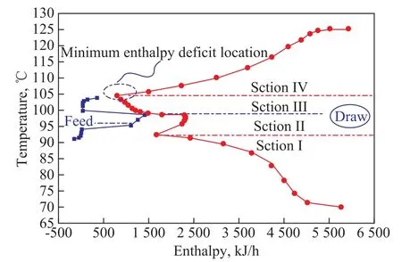
Figure 3 CGCC profile of DWC with q=1
Based on the earlier research, the heat load of virtual intermediate heat exchanger at each stage in the rectifying section of each part of four columns model can be calculated by equation (1)[13]:and that in the stripping section can be calculated by equation (2):


The amount of heat transferred between the virtual intermediate heat exchangers can be calculated by equation(3), in whicheis one of the stages in the side-draw section,andfis the other stage in the prefractionator which has the same position ase. For this case, the maximum heat transfer quantity in the optimal heat transfer region across the wall is 313.32 kJ/h. Likewise, the optimal heat transfer process for the feed thermal conditionsq=0.5 andq=1.5 can be analyzed according to the method described above,and the results show that the adiabatic process occurring across the whole wall is the most suitable forq=0.5 (which is constrained by temperature difference between the sidedraw section and the prefractionator, and the detailed content will be described in next paragraph), while the heat transfer process introduced between sections Ⅲ to Ⅵ is the best appropriate process forq=1.5, and its maximum heat transfer quantity is 472.36 kJ/h.
Figure 5 shows the in fluence of feed thermal conditionsqon the temperature difference and the beneficial heat transfer region between side-draw section and prefractionator (the temperature in side-draw section minus that in prefractionator equals the temperature difference), the stages contained in the shadow area are the ones involved in the beneficial heat transfer region. Whenqhas lower value (e.g.:q=0.5), despite the existence of the beneficial heat transfer region (as analyzed by CGCC, as shown in Figure 6.a, that this region is the corresponding parts of sections Ⅲ to Ⅵ.), the temperature difference between two sides of the wall has negative value, which leads to no heat-transferring driving force. Whenqhas higher value, the temperature difference, the maximum heat transfer quantity, and the potential for energy saving will increase with an increasingq. Besides, whenq=1, the beneficial heat transfer region is the area below the feed stage in the prefractionator (from 6thto 15thstages in prefractionator)according to the method described in Segment 2, and the beneficial heat is transferred along the direction from the side-draw section to the prefractionator, however it can be also observed that the temperature differences on 9th-14thstages have negative values, which means that the temperature in the side-draw section in the range of 9th—14thstages is lower than that in the prefractionator, therefore the beneficial heat transfer region cannot be realized completely because of the limitation of temperature difference, and only the heat transfer process taking place in the range of 6th—8thand 14th—15thstages can play the beneficial role.Whenq= 1.5, as shown in Figure 6.b, the beneficial heat transfer region does not change, and the temperature difference allows the heat transfer process to occur in the beneficial heat transfer region, which also verifies that the maximum heat transfer quantity across the wall withq= 1.5 is larger than that withq= 1.
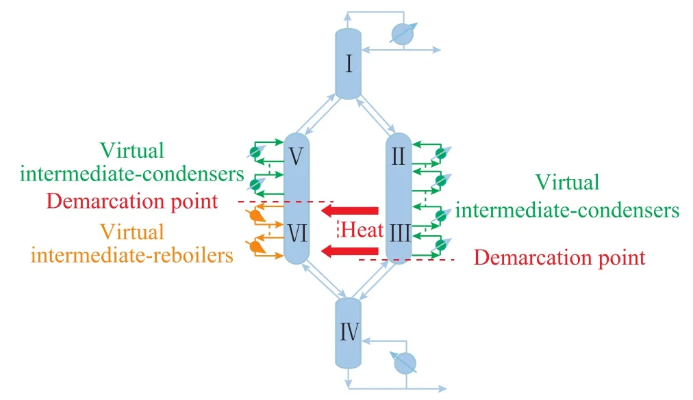
Figure 4 Schematic diagram of four-column models with different types of virtual heat exchangers installed
3.3 Effect of middle component composition of feed on heat transfer process across the wall
Figure 7 shows the effect of mole composition of middle component (cB) in feed which changes within the range of 0.4—0.6 on the maximum heat transfer quantity across the wall and the energy saving effect (i.e.: the ratio of maximum heat transfer quantity across the wall to reboiler heat duty of DWC). It can be seen that whencBchanges within the range of 0.45—0.47, the maximum heat transfer quantity and the energy saving effect increase relatively greater with the increase ofcB, and whencBis greater than 0.47, the heat transfer quantity and the energy saving effect increase slightly.Figure 8 shows the in fluence ofcBon temperature difference between the prefractionator and the side-draw section, the stages contained in shadow area are the ones involved in the beneficial heat transfer region. Compared withq, the number of stages contained in the feasible beneficial heat transfer region, which is limited by temperature difference, does not change much with the variation ofcB. With the increase ofcB, the temperature difference in the beneficial heat transfer region and the driving force would decrease, and the maximum heat transfer quantity would increase (whencBis equal to 0.4, 0.5, and 0.6, the maximum heat transfer quantity across the wall calculated by equations (1)—(3)is 86.78, 313.32, and 388.42 kJ/h, respectively); namely,based on an overall consideration of Figure 7 and Figure 8,in order to realize the optimal energy saving effect with larger value ofcB, the heat transfer resistance at two sides of the wall needs to be very small. In addition, the heat transfer resistance at two sides of the wall is limited by the heat conduction resistance of the wall and the thermal convection resistance of flow at two sides of the wall, the most effective and direct way to reduce the heat transfer resistance is to change the flow pattern at two sides of the wall, which causes the change in flow rate of liquid and vapor at two sides of the wall, and can indirectly affect the liquid split ratio and the vapor split ratio. Furthermore, the liquid split ratio and the vapor split ratio will have influences on heat transfer process across the wall.
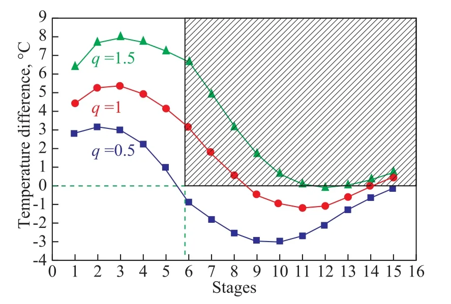
Figure 5 Effect of feed thermal conditions on temperature difference across the wall
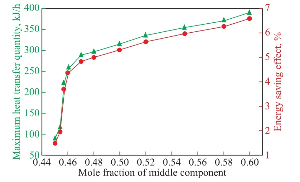
Figure 7 Effect of cB on maximum heat transfer quantity and energy saving effect
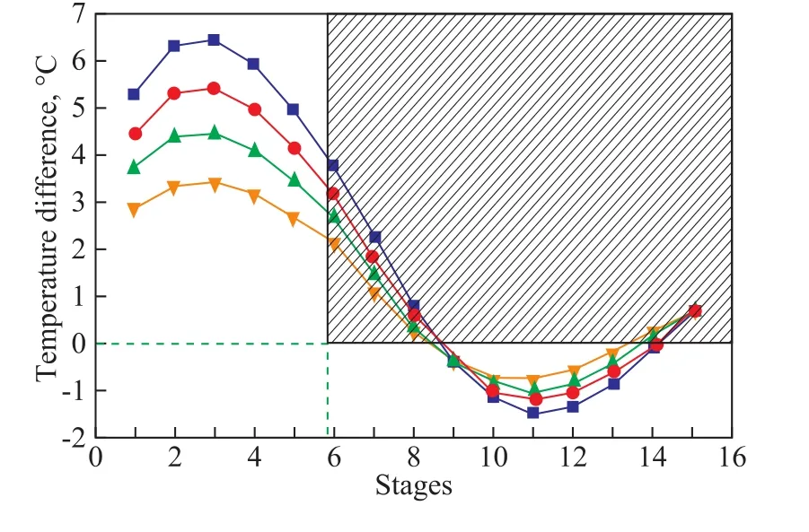
Figure 8 Effect of cB on temperature difference across the wall
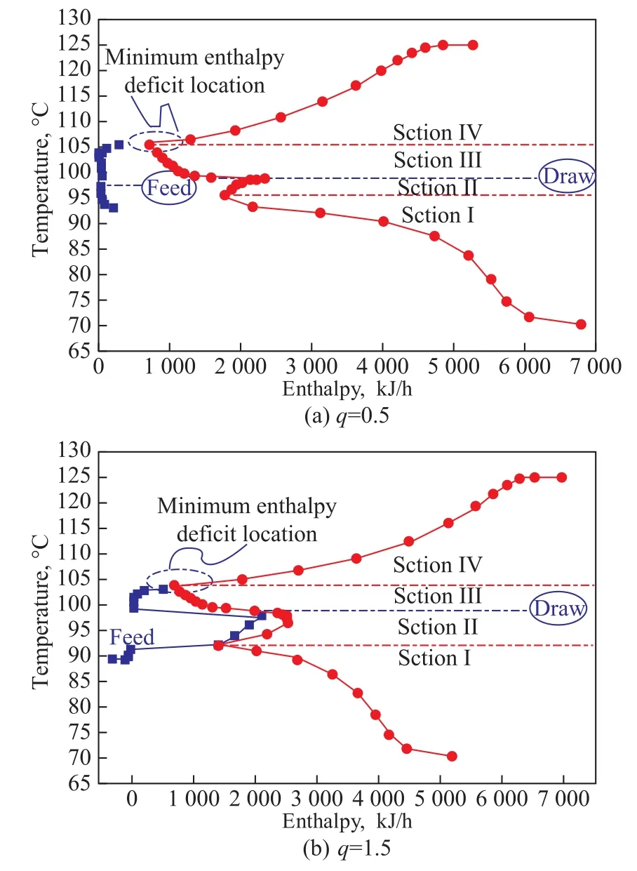
Figure 6 CGCC profile with different q
Figure 9 investigates the effect of the liquid split ratio(RL) and the vapor split ratio (Rv) on heat transfer process across the wall. It can be seen that whenRvbecomes a constant value, the maximum heat transfer quantity across the wall increases with the increase ofRL; compared with larger value ofRL, whenRLhas lower value, the maximum heat transfer quantity shows a significant variation; whenRLbecomes a constant value, the maximum heat transfer quantity across the wall will decrease with the increase ofRv(as shown along the arrows direction).

Figure 9 Effect of RL and Rv on maximum heat transfer quantity across the wall
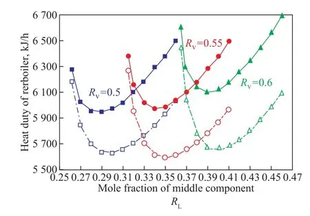
Figure 10 Effect of RL and RV on reboiler heat duty
After the heat is transferred across the wall and the maximum heat quantity is achieved (as shown in Figure 10, solid lines indicate the adiabatic process, and dash lines indicate the heat transfer process introduced across the wall), it is confirmed that the reboiler heat duty initially drops to a minimum value followed by a steep rise with the changes ofRLandRV, and the reason for that change is the relationship betweenRLandRV,RLand reflux ratio (R). As shown in Figure 11,RLincreases with the increase ofRV, because the increase ofRLrepresents the growth of liquid flow rate in the prefractionator,the vapor flow rate in prefractionator provided by the public stripping section needs to improve (scilicet,RVincreases) to ensure the same separation effect. Judging fromRL-Rcurve, it shows thatRfirstly decreases to minimum and then increases with an increasingRL, the reason is that the vaporization of liquid streams in the prefractionator and the condensation of vapor streams in the side-draw section increase with the heat transfer process introduced between the side-draw section and the prefractionator, which leads to the consequence that more liquid streams in the prefractionator and more vapor streams in the side-draw section should complete the mass transfer to make the increased internal reflux ratio, while the required external reflux ratio decreases; but the external reflux ratio cannot be dropped so much to fulfill the separation task, therefore, the external reflux ratio should be raised after it drops to a minimum value with the increase ofRL.Upon considering thatRand reboiler heat duty have a direct corresponding relationship, the change tendency of reboiler heat duty is the same asRvarying withRLandRV.

Figure 11 Relationships between RL and RV, and between RL and R
It can be also clearly seen that compared with the adiabatic process, the reboiler heat duty reduces by more than 5 percentage points after the heat transfer process is introduced across the wall, and also proves that the introduction of heat transfer process across the wall plays its role in enhancing the energy saving effect. Simultaneously it also discovers that the optimal operating zone combined byRLandRvshifts (considering the operating under control, around the minimum energy consumption there is an area with gentle curve fluctuating within 1% as defined), and it also verifies that the change ofcBfor realizing maximum energy saving effect altersRL,RVand their optimal operating zone, which brings the in fluence on subsequent dynamic control for DWC.
4 Conclusions
Based on the analysis of CGCC, the process of heat transfer among the virtual intermediate exchangers is introduced in DWC. The heat transfer process between the virtual intermediate exchangers is used to replace that between the side-draw section and the prefractionator. Particularly, the heat transfer process between different types of virtual intermediate exchangers is able to realize the thermal-coupled effect, which can obtain a maximum energy saving effect of DWC.
Focusing on the influence of feed properties on heat transfer process across the wall, the results show that whenqhas lower value despite the existence of the beneficial heat transfer region, the temperature difference between two sides of the wall has a negative value, which cannot lead to a heat-transferring driving force. Whenqhas higher value, the temperature difference between the prefractionator and the side-draw section, the maximum heat transfer quantity and the potential for energy saving will increase with the increase ofq. With the limitation of temperature difference across the wall, the beneficial heat transfer effect between a certain range of stages, which are contained in the optimal heat transfer region, cannot be realized completely for a specific value ofq.
In comparison withq, the number of stages contained in the feasible beneficial heat transfer region, which is limited by temperature difference, does not change much with the change ofcB. However, the change ofcBbrings about the variation of liquid split ratio (RL) and vapor split ratio (RV).Upon considering the relationship ofRL,RVand the heat transfer process, the optimal operating zone combined byRLandRVwill alter with different heat transfer processes,and therefore identifying the beneficial heat transfer region across the wall, which is suited for differentcB,should be related to the variation ofRLandRV. Therefore, for achieving a maximum energy-saving effect of DWC, differentqandcBneed to find its own corresponding suitable heat transfer process across the wall, the cross-wall adiabatic process or the cross-wall heat transfer process between two sides of wall are not suited for all feed properties.
Acknowledgments:This work was supported by the Natural Science Research Youth Foundation of Hebei Higher Education of China [QN2016084]and the National Natural Science Foundation of China[21878066].
杂志排行
中国炼油与石油化工的其它文章
- Numerical Simulation of Optimization of Mixing Tank for Residue Upgrading Reactor
- Biodegradability and Tribological Properties of Mineral Base Oil Enhanced by Caprylic Methyl Diethanolamine Phosphate Ester
- Enhanced Anti-Wear Property of Low Viscosity Engine Oil for Sequence IVB Engine Test Meeting the GF-6 Specification
- Study on Flue Gas Desulfurization Process with Selective SO2 Removal by N-formylmorpholine
- Research and Application of Image Recognition Technology in Microscopy Diagnosis of Catalytic Cracking Catalysts
- Evaluation of Inocula and Packing Material for Acceleration of Start-Up in Biofilters
