Numerical Simulation of Optimization of Mixing Tank for Residue Upgrading Reactor
2019-07-15BaoDiTangXiaojinZhuZhenxing
Bao Di; Tang Xiaojin; Zhu Zhenxing
(SINOPEC Research Institute of Petroleum Processing, Beijing 100083)
Abstract: For studying the mixing tank for RMAC (residue upgrading to maximize asphaltene conversion) reactor, the CFD simulation was employed to simulate the flow field in the mixing tank. The dispersion of liquid-liquid phase in the mixing tank and the power of turbines were investigated. The simulation results showed that compared with the original doublelayer propeller, the A310-swept double-layer impellers could reduce the liquid heterogeneous degree by 27.5% and the stirring power by 3.25%. The in fluence of rotation speed on the heterogeneous degree and stirring power was investigated,and the critical rotation speed was obtained. The optimal rotation speed was determined to be 240 r/min. The heterogeneous degree was 0.19 and the minimum stirring power was 10.89 W. By optimizing the impeller selection and process conditions,the overall performance of the mixing tank could be significantly improved.
Key words: liquid-liquid mixing; impellers; numerical simulation; critical rotation speed
1 Introduction
Liquid-liquid mixing is a key unit operation in chemical processes, aiming at uniformly dispersing the two immiscible liquids to achieve the effect of intensive mixing.Therefore, the stirred reactor is not only used in various chemical reaction processes, but also in the non-reaction processes, such as premixing and cooling processes[1].The impeller is the core of the stirred reactor, and its type and size determine the mixing effect of the equipment.According to the different circulation types of the liquids in the stirred reactor, the impellers can be generally divided into two types: axial impeller and radial impeller. The axial impeller conveys the fluid along the axial direction to form an integral circulation. The radial impeller conveys the fluid along the radial direction, and the fluid separates up and down after it reaches the wall of reactor and forms two cycles above and below the stirring impeller, respectively[2].Radial impellers are usually turbines with several straight blades or curved blades, such as the Rushton disc turbine(RDT), the back-swept impeller, the Brumagin impeller, etc.The mixing efficiency of radial impellers is higher than that of axial impellers with lower power consumption, which is the advantage of radial impellers. The axial impellers usually have several pitched blades, such as the propeller, the pitched blade turbine (PBT), etc. There are also studies[2]suggesting
that PBT is between the axial and radial impellers, which can also produce a radial flow pattern. In comparison with the radial impellers, the axial impellers can consume less power.In order to reduce the energy consumption and improve the mixing efficiency, a lot of companies have developed new axial and axial-radial mixed impellers. For instance,there are the A series impellers developed by LIGHTNIN,the INTERPRO impellers developed by EKATO, and the HPM impellers developed by ROBIN. For the liquidliquid mixing system, the radial impeller can completely disperse the two liquid phases at a low rotation speed,while the axial impeller can achieve the same dispersion effect with less power consumption[3]. Currently, the back-swept impeller and the Brumagin impeller are radial impellers with excellent dispersion effect. As a commonly used axial impeller, the LIGHTNIN A310 impeller is equipped in the stirred reactors of various processes.
The selection of the impellers strongly depends on the physical properties of the mixing system, which makes it difficult to choose the proper impellers by using a uniform standard. Fortunately, as a common tool for studying hydrodynamics, the computational fluid dynamics(CFD) technology overcomes the difficulties on measuring the multiphase flow field by experiment. Nowadays, lots of researchers have performed the CFD simulations to study the liquid-liquid mixing process. Alopaeus[4-5]employed the population balanced model (PBM) to simulate the droplet dispersion in another liquid phase, and the distribution of the droplet size is obtained through the simulation. Wang[6]developed the standardk-εturbulence model to express the interaction between the impeller and baffles, and the simulation results agreed well with the experimental data.Cheng[7]employed an anisotropic two-phase explicit algebraic stress model to simulate the liquid-liquid mixing processes in the stirred cylindrical tank equipped with the Rushton turbine, and the results showed that the key features of mixing process could be successfully predicted by this model. Wang[8]simulated the liquid-liquid-solid three phase mixing process for measuring the phase holdup in the stirred tank, and made a comparison between the simulation results and the experimental data. The previous works on liquid-liquid mixing by using the CFD method mainly focused on the model for stirred systems, and rarely paid attention to the selection of the impellers, which was critical to the liquid-liquid mixing effect. Especially for a specific process, such as the premix for residue upgrading to maximize the asphaltene conversion (RMAC) reactor, the impeller type could determine the reaction efficiency of the RMAC reactor.
In the RMAC process[9], the reaction product is delivered to the subsequent process after separation. While the unreacted residue needs to be recycled, mixed with the fresh reactant and re-injected into the reactor. In this process, the mixing tank plays an important role of thoroughly mixing the recycled oil and the fresh oil. In order to improve the mixing efficiency of the tank, it is crucial to select the proper impellers and determine the optimal rotation speed. In this study, the computational fluid dynamics (CFD) simulation was carried out for the premixing tank of the RMAC reactor, and the mixing effect of the tank was improved by optimizing the type of impellers and process conditions.
2 Work flow of the Mixing Tank
The non-continuous batch operation was adopted for the mixing tank. At the beginning, 20 kg of fresh oil and 20 kg of recycled oil were added into the mixing tank.Then the mixing tank started working until the fresh oil and recycled oil were thoroughly commingled. The structure of the mixing tank is shown in Figure 1. The inner diameter of the tank is 400 mm and the tangent height is 700 mm. The mixing tank is equipped with an elliptical bottom with a height of 125 mm. The doublelayer impellers are adopted in this tank. The lower layer impeller is 50 mm above the bottom of the tank, and the spacing between the two layers is 170 mm.

Figure 1 The framework of the mixing tank structure
In the previous experimental work, the double-layer propellers were adopted to disperse the fresh and recycled oil, and the rotation speed was set at 180 r/min. However,the heavy components in the recycled oil could hardly be dissolved in fresh oil in a short time, which would lead to low mixing efficiency. Therefore, a uniform dispersion of the two phases is expected to improve the mixing effect of the tank. Optimizing the selection of the impellers is an effective way to achieve this improvement. Upon considering that the axial impellers can effectively improve the suspension of the heavy phase at the bottom, the LIGHTNIN A310 impeller is employed for the lower layer impeller. The diameter of A310 impeller is 160 mm, which is same as that of the original propeller. As for the upper layer impeller, two proposals are evaluated in this work.
One is to select a back-swept impeller, which can achieve better dispersion effect at the same speed, and the other is to use an A310 impeller that can prevent the light phase from gathering near the shaft and the upper layer impeller.For both types of upper layer impellers, the diameter is increased to 200 mm for achieving better dispersion effect.
3 Numerical Models
3.1 Governing equations
The mixing tank is filled with recycled oil and fresh oil,which are assumed to be immiscible with each other during the mixing process. Moreover, the mass transfer between the two phases is not considered in the model.Both the fresh and recycled oil are treated as a pair of interpenetrating and continuous fluids. Based on the above assumptions, the Euler-Euler model is employed to simulate the liquid-liquid two-phase mixing process in the mixing tank, with fresh oil serving as the continuous phase and recycled oil — as the discrete phase. The drag force is considered as the interaction between the discrete phase and the continuous phase, and the Schiller-Naumann drag model is adopted to calculate the drag coefficient. The k-ω SST turbulence model is used to calculate the turbulent viscosity. The governing equations employed in the simulation are shown in Table 1.

Table 1 Governing equations
3.2 Geometric model
The three-dimensional geometry of the pilot-plant scale mixing tank and the double layer impellers was established, as shown in Figure 2. Furthermore, the geometric model of the propeller, the LIGHTNIN A310 impeller, and the back-swept impeller was established,respectively. The specific structural parameters of the above impellers were obtained from the literature reports[10-12]. Due to the complexity of the impeller structures, it was difficult to generate structured grid for the mixing tank. Thus, the computational domain was meshed by using the tetrahedral unstructured grid. All the grids were refined at the zones near the impellers, and the mesh number of the mixing tank with propellers, backswept impeller, and A310 impellers was 645, 618; 764,152; and 764, 320, respectively.

Figure 2 The structure and grids of the mixing tank and impellers
3.3 Boundary conditions and physical properties
The materials involved in this process and their physical properties are shown in Table 2. The wall of the mixing tank, the impellers and the agitating shaft were set as nonslip wall boundary, while the top of the tank was defined as the free-slip wall boundary. The multi reference frame(MRF) method was employed to simulate the rotation of the impellers. The flow equations were discretized with high resolution scheme, which could provide high accuracy. The iteration time step was set as 0.01s.
In order to simulate the non-continuous batch operation of the mixing tank, 20 kg of fresh oil and 20 kg of recycled oil, which were uniformly dispersed, were placed at the bottom of the mixing tank at the time of initialization. The rest of the tank was filled with air. A transient simulation was carried out to investigate the mixing of the two phases, and the whole mixing process lasted one hour.

Table 2 Physical properties of the materials
4 Results and Discussion
4.1 Flow characteristics
In the double-layer stirring system, the interaction between the two impellers are not strong when the spacing of the impellers is larger than 1/2 of the diameter of the tank. And both the two impellers produce their own vortexes independently[13-14]. Figure 3 shows the flow field generated by the three different impellers at the same rotation speed. It can be seen from Figure 3 that the double-layer propellers produce two independent vortexes beside the upper and lower impellers, respectively. The vortex generated by the lower layer impeller is larger than the upper one, which can elevate the recycled oil at bottom effectively. The A310-back-swept double-layer impellers also produce two vortexes beside the impellers.Being different from the double layer propellers, the back-swept impeller is a radial impeller, and the radial impeller of the upper layer produces two vortexes above and below it, respectively. Due to the increased diameter of the upper layer impeller, the vortex below it interacts with the vortex generated by the lower A310 impeller,and forms a large vortex at the bottom, which implies that the A310-back-swept double-layer impellers have a significant effect on the dispersion of the fresh and recycled oil. The double-layer A310 impellers produce a smaller vortex and the strength of the flow filed is weak,making it difficult to generate an effective circulation of the oil.
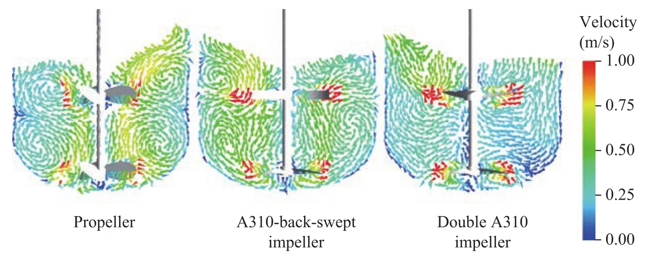
Figure 3 The flow field generated by the three different impellers (N=180 r/min)
The axial velocity of the fluid in the mixing tank has a crucial influence on the liquid-liquid mixing. Figure 4 shows the axial velocity profiles of different impellers at the same rotation speed. It can be seen that the axial velocity fluctuates significantly for the double-layer propellers, which is beneficial to the dispersion of the two phases. However, the velocity directs downward near the lower impeller, and it directs upward near the upper impeller, which is not conductive to the liquid-liquid dispersion. The velocity fluctuation of the A310 doublelayer impellers is relatively weak, leading to negative effect of the two-phase mixing. The A310-back-swept double-layer impellers overcome the shortcomings of the above two impellers. It can elevate the heavy phase and push down the light phase effectively, and can contribute to uniform dispersion of the two phases.
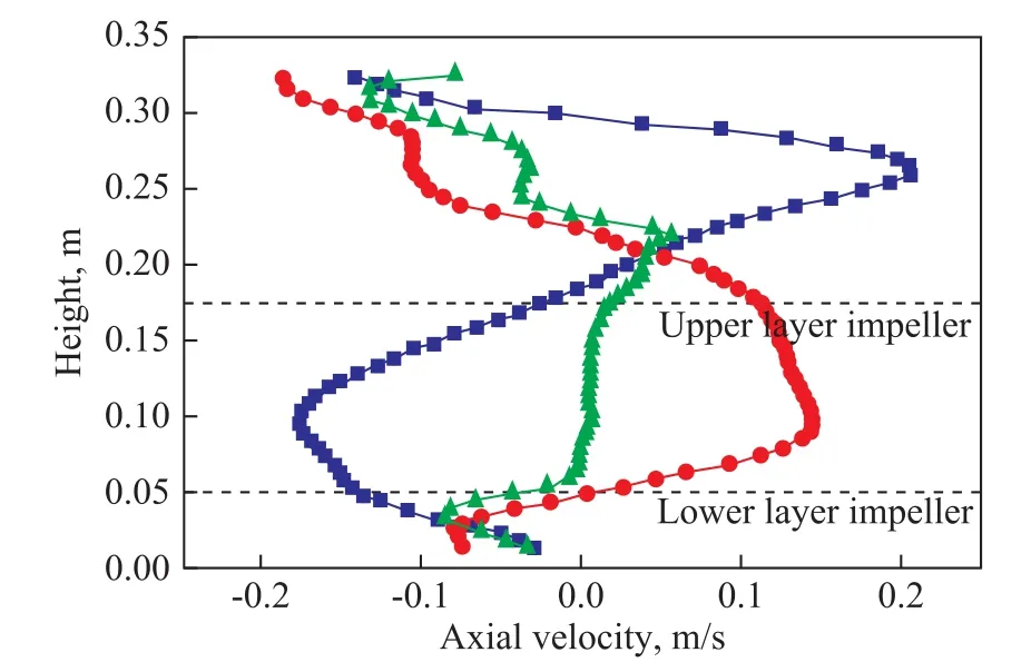
Figure 4 Axial velocity distribution of different doublelayer impellers (N=180r/min, r =100mm)
4.2 Mixing effect
Figure 5 shows the volume fraction distribution of fresh oil and recycled oil in the mixing tanks equipped with different impellers. The simulation results reveal that the double layer propellers have an undistinguished effect on the dispersion of the two phases, and there is a significant phase interface between the fresh and the recycled oil. The fresh oil gathers in the upper layer and around the stirring shaft, while the recycled oil remains at the bottom of the mixing tank. The suspension height of the recycled oil is about 0.2 m from the bottom. Due to the weak flow field strength, it is difficult to disperse the fresh and recycled oil effectively by the double-layer A310 impellers. The A310-back-swept double-layer impellers can achieve better dispersion effect than the other two impellers. The recycled oil is dispersed uniformly in the main part of the mixing tank, but there is still a small amount of fresh oil gathering around the upper layer impeller, which can be restrained by increasing the rotation speed[15].
Furthermore, the axial distribution of the recycled oil volume fraction in the mixing tank can be obtained by quantitative analysis, as shown in Figure 6. It indicates that for the double-layer A310-back-swept impellers,the volume fraction of recycled oil maintains at 0.5 approximately in a wide range of height. While for the double-layer propellers, the volume fraction of recycled oil reduces sharply from 0.6 to less than 0.4 with the increase in height at the region above the upper layer impeller, leading to a significant phase interface in the mixing tank. As for the double-layer A310 impellers,the recycled oil remains at around the lower layer impeller due to the weak flow field strength between the two layers of impellers, and the phase interface between the fresh oil and the recycled oil is obvious.The mixing effect of the liquid-liquid stirring system can be characterized by the heterogeneous degree of the dispersed phase[16]. The sampling point is 5 cm away from each other, and all the points are selected below the liquid level in the mixing tank. In this work, a total of about 400 sampling points are adopted to calculate the heterogeneous degree of the system. By measuring the volume fraction of the recycled oil at the sampling point, the heterogeneous degree of the recycled oil in the mixing tank can be calculated according to the following formula:
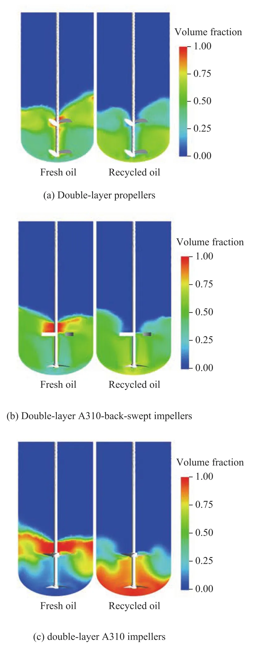
Figure 5 The distribution of the volume fraction of the fresh and recycled oil in the mixing tank

wherenis the number of sampling points,αl, irepresents the volume fraction of the recycled oil at the sampling point, andαl,avestands for the average of the volume fraction of recycled oil in the mixing tank. Usually, a uniform distribution in mixing tank can be achieved when the heterogeneous degree is less than 0.2[16]. Table 3 shows the heterogeneous degree of the recycled oil in the mixing tanks equipped with three different impellers. The results indicate that the heterogeneous degree with the double-layer A310 impellers is significantly higher than that with the other two types of impellers, and it means that the double-layer A310 impellers are ineffective for liquid-liquid mixing. In comparison with the double-layer propellers, the doublelayer A310-back-swept impellers can improve the dispersion effect obviously, especially at a relatively low rotation speed.By comparing with the original double-layer propellers, the heterogeneous degree of recycled oil reduces by 27.5%. To sum up, the A310-back-swept double-layer impellers have the most obvious effect on the mixing of the fresh oil and the recycled oil in the tank.
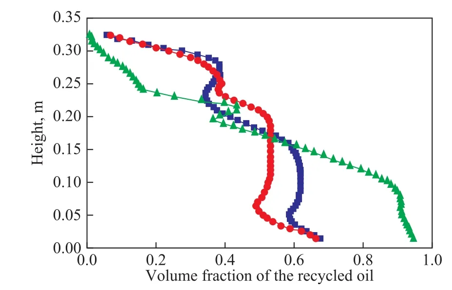
Figure 6 Axial distribution of recycled oil volume fraction achieved by different double-layer impellers(N=180 r/min, r =100 mm)

Table 3 The heterogeneous degree of the recycled oil(N = 180 r/min)
4.3 The critical rotation speed
In the liquid-liquid stirring system, the critical rotation speed generally refers to the minimum rotational speed for complete dispersion of the two phases[3]. Therefore,the critical speed can be determined according to the heterogeneity of the recycled oil at different rotational speeds. Figure 7 shows the relationship between the heterogeneous degree of the recycled oil and the rotational speed in the mixing tank equipped with the double-layer A310-back-swept impellers. According to Figure 7 the rotational speed at a heterogeneous degree of 0.2 represents the critical speed. It can be seen from the test results that the critical speed of the A310-back-swept double-layer impellers equates approximately to 231 r/min. As the rotational speed increases, the heterogeneous degree of the recycled oil decreases rapidly. When the rotational speed exceeds the critical speed, the heterogeneous degree can hardly change with the increase of the rotational speed.

Figure 7 Relationship between the heterogeneous degree of the recycled oil and the rotation speed in the mixing tank
4.4 The minimum stirring power
The stirring power is one of the key parameters for the design of impellers, which is related to the selection of electric motors. By using the CFD simulation, the torque of the impellers and the shaft can be obtained, and then the stirring power can be calculated according to the following formula:

whereTis the torque of the impellers and the shaft, andNstands for the rotation speed (r/min). Table 4 shows that the minimum stirring power for the three different impellers is determined at a rotation speed of 180 r/min.The results reveal that the A310-back-swept doublelayer impellers not only can achieve better mixing effect than the double-layer propeller, but also need lower stirring power. The stirring power of the doublelayer A310 impellers is significantly lower than that of other two impellers, which is determined by the unique structure of the A310 impellers. It implies that to achieve the same mixing effect of the other two impellers, the double layer A310 impellers require a high rotation speed to increase its input power. Therefore, for a specific electric motor with a certain output power, the A310-back-swept double-layer impellers are preferred for minimizing the stirring power and achieving an excellent mixing effect.
The relationship between the minimum stirring power and the rotation speed of the A310-back-swept double-layer impellers is shown in Figure 8. It illustrates that for the A310-swept double-layer impellers, the minimum stirring power increases dramatically with the increase of the rotation speed. Therefore, in order to achieve a uniform distribution of the two liquid phases with a relatively low stirring power, it is necessary to operate the mixing tank with a critical rotation speed, namely a rotation speed of 231 r/min. At a rotation speed of 240 r/min, the minimum stirring power required by the A310-back-swept doublelayer impellers is 10.89 W, which is much lower than the electric motor output power of 550 W. Therefore, the optimum operating speed of the A310-back-swept double impellers is suggested to be 240 r/min.

Table 4 The stirring power of different impellers(N=180 r/min)
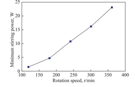
Figure 8 Relationship between the minimum stirring power and the rotation speed
5 Conclusions
This work focuses on the liquid-liquid two-phase mixing process in the mixing tank for the RMAC reactor. By using the CFD simulations carried out in this work, the selection of the impellers and the process conditions of the mixing tank were optimized. As a result, in comparison with the original double-layer propellers and the double-layer A310 impellers, the A310-back-swept double-layer impellers had the best mixing effect. At the same rotation speed, by using the optimal impellers, the heterogeneous degree of the recycled oil was reduced by 27.5%, and the minimum stirring power was reduced by 3.25%. Furthermore, the critical rotation speed was obtained through the analysis of the heterogeneous degree, and for the A310-back-swept double-layer impellers, the critical rotation speed was 231 r/min.The recycled oil could be uniformly distributed when the rotation speed exceeded the critical rotation speed.Upon considering both the mixing effect and the stirring power, the A310-back-swept double-layer impellers were suggested for this process, and the optimal rotation speed was 240 r/min.
Acknowledgement:The research is supported by the Major Science and Technology Project of SINOPEC (ST18012-4).
杂志排行
中国炼油与石油化工的其它文章
- Effect of the Morphology of ZnO Support on the Desulfurization and Regeneration Performance of Ni/ZnO Catalyst
- Optimization of Dividing Wall Column with Heat Transfer Process Across the Wall for Feed Properties Variation
- Methane Storage and Synthesis of HKUST-1 Prepared with Different Solvent
- Research on Hydrogenolysis of Glycerol to 1, 2-Propylene Glycol by Using Supported Raney-Cu/Al2O3
- Synthesis of Nanosized SSZ-13 Zeolite and Performance of Its Mixed Matrix Membrane for CO2/CH4 Separation
- Intelligent Transformation and Upgrading of Oil Refining& Petrochemical Industries in China: Investigation &Application
