Effect of the Rim Seal Configurations on the Hot Gas Ingestion into the Rotor-stator Cavity*
2019-06-18XingyunJiaJieZhouZhiqiangAnQunZhengHaiZhang
Xing-yun JiaJie ZhouZhi-qiang AnQun ZhengHai Zhang
(1.College of Power and Energy Engineering,Harbin Engineering University,Harbin,China,2.Science and Technology on Altitude Simulation Laboratory,China Gas Turbine Establishment,China Aviation Industry Corporation,Chengdu,China,3.AECC Hunan Aviation Powerplant Research Institude,Zhuzhou,China)
Abstract:The effect of rim seal configurations on the flow and heat transfer characteristics in a turbine cavity and the rim seal clearance flow are computed by using a numerical method for conjugate heat transfer.Aradial clearance at high radius can properly block the ingestion air and purge flow into the rim clearance region, leading to a better temperature distribution of the turbine disc and cavity with approximately 3%-10%increase in seal effectiveness when compared to an axial clearance rim seal at high radius. The radial- axial clearance rim seal keeps the advantages of a radial-clearance, further reducing the negative effect of ingestion gas on the temperature of the rotor and stator discs.Under the condition of minimum sealant flow rate for the radial-axial clearance rim seal, the seal effectiveness of the radial-axial clearance rim seal is 5.29%higher than that of the axial-clearance rim seal, and the air-cooling aerodynamic efficiency of the radial-axial clearance rim seal is 1.8%higher than that of the axial-clearance.
Keywords:Rim Seal,Radial-axial Clearance Rim Seal,Hot Gas Ingestion,Rotor-stator Cavity,Conjugate Heat Transfer.
Nomenclature
aRadius of platform/m
bRadius of seal/m
CFFlow coefficient
CpPressure coefficient
CsHeat capacity of solid/(J/kg·K)
GcSeal-clearance ratio
ReφRotational Reynolds number
RewAxial Reynolds number
λsThermal conductivity/(W/m·K)
λTTurbulence flow coefficient
Ω Angular speed of disc/(rad/s)
εSeal effectiveness
εcConcentration rim seal effectiveness
ηAir-cooled aerodynamic efficiency
ΦNon-dimensional sealing parameter
βSwirl ratio
Abbreviations
CHT Conjugate Heat Transfer
EI External induced Ingress
RI Rotational induced Ingress
0 Introduction
In modern gas turbine,about 10%to 30%compressed air of the high pressure compressor is bled from several compressor stages for the cooling,sealing and other functions of the air system.Using this bled flow in an efficient way is critical for the compressor efficiency,cooling effect of turbine,engine reliability and life.Johnson et al.[1]showed that a 50%reduction in the amount of bled flow increases the whole efficiency of 0.5%for a two-stage turbine,while reducing fuel consumption by 0.9%.
From 1998 to 2005,European research institutions participated in the Internal Cooling Air System of Gas Turbine(ICAS-GT and ICAS-GT 2)programs to reduce 1%rated fu-el consumption of the gas turbine by reducing the air consumption of the air system[2-4].In Main Annulus Gas Path Interactions(MAGPI)program,flow and heat transfer characteristics in the rim seal are of interest[5,6].Owen et al.[7-11]carried out systematic theoretical and experimental research on rim seals,classified the phenomena of hot gas ingestion as RI(Rotating induced ingress)and EI(External induced ingress),proposed and verified the prediction model of sealing effectiveness based on concentration measurements,and compared the flow characteristics in different rim seal geometries.Sangan et al.[12]proposed the double-clearance rim seal geometry and Scoibe et al.[13,14]proposed the finned double rim seal geometry,and the experimental results showed that the finned double rim seal significantly reduced the minimum mass flow rate of cooling air approximately 10%when compared to the double-clearance.Chew et al.[15,16]combined experiment and three-dimensional computational fluid dynamics(CFD)calculations to further understand rim seal problems,and indicated that the asymmetric annulus flow provided the dominant driving force for ingestion,as well the disc pumping effect increased the level of ingestion.
Bohn et al.[17-19]focused on the effect of rim seal geometry,configuration and rotor blades on hot gas ingestion into rim cavity of axial turbine stage,and estimated the minimum sealing flow rate by the characteristics of the main flow and seal geometry,and the experimental results of minimum seal mass flow rate showed very good liner behavior,such as those given by Phadke and Owen.Johnson et al.[20,21]investigated the effect of the separation between the trailing edge of vane and the leading edge of the blade on hot gas ingestion in an axial clearance rim seal.One of the most important conclusions was that the blade bow wave had a similar or even larger influence as the pressure field of trailing vanes on the rim seal ingestion.
Luo et al.[22,23]proposed that the concentrationbased and temperature-based sealing efficiencies of rim seals were different through the mass and heat transfer experiments.The applicability of these results is limited by the conditions of the test.Flow and heat transfer characteristics in rim seal region and turbine cavity are investigated under the actual working conditions.Numerical approach of conjugate heat transfer is used to fully consider the interactions between mainstream,cooling air and turbine discs.Turbine disc geometry,blade profile and rim seal(axial-clearance rim seal,radial-clearance rim seal,radial-axial clearance rim seal)parameters are consistent with the gas ingestion test rig[9]of University of Bath.Seal effectiveness,flow and heat transfer characteristics in turbine cavity flow,effect of purge flow on mainstream are mainly concerned.Understanding these flow and heat transfer mechanisms is fundamental to minimizing ingestion gas and purge flow,thus minimizing the mainstream performance penalty.
1 Numerical Approach and Validation
Figure 1(a)[9]shows a high pressure turbine stage and its corresponding rim seal position.This rim seal consists of endwall extension of the turbine disc and the seal ring.Rim seals are critical connections of the annulus flow path and internal cooling air system in a gas turbine.Inner cooling flow is bled from several compressor stages through the rim seal to prevent hot gas ingestion from the annulus.
1.1 Objective for numerical approach validation
Figure 2 shows the cross section of the gas ingestion test rig of Univ.of Bath[9-10].A series of systematic experimental researches on rim seal test have yielded fruitful academic results[7-14].In this gas ingestion test rig,the radial sealant flow enters at low radius into the wheel-space region.The concentration effectiveness of rim seal is carried out based on gas concentration measurements by adding approximately 3%CO2in the sealant inflow.
All validation work is based on this gas ingestion test rig.The model used for numerical validation is a typical axial clearance rim seal geometry,as shown in Fig.2.The radius of the rim sealbis 190 mm,the axial seal clearanceSc,axis 2 mm,and the seal-clearance ratioGcis 0.010 5.The separation between the trailing edge of guide vane and leading edge of rotor blade is 12 mm.The numerical model includes 32 vanes and stator discs and 41 blades and rotor discs.Details of the axial-clearance rim seal geometry are summarized in Table 1,and the operational conditions of the test are given in Table 2.

Fig.1 High pressure turbine stage and its rim seal[9]

Fig.2 Experimental test rig of University of Bath[9]

Tab.1 Geometry parameters of axial-clearance rim seal

Tab.2 Operational conditions of the test
The periodic conjugate model includes three fluid domains and two solid domains,as shown in Fig.3.There are two configurations for the turbine cavity fluid domain.For configuration A,the turbine cavity fluid domain is a rotational computational domain,and the location of the rotational and static domain interface in annulus is located at 1 mm upstream of the axial seal clearance.For configuration B,the turbine cavity fluid domain is non-rotating computational domain,and the location of the rotational and static domain interface in the annulus is 2 mm downstream of axial seal clearance.The grids used for the calculation and the fluidsolid and fluid-fluid interfaces are shown in Fig.4.The interface type between the static and rotating domains is frozen rotor.All fluid domains are structured grids and solid domains are unstructured grids,grids near wall and clearance regions are refined.The grids are composed of 2.142 million elements after grid dependency validations.

Fig.3 Two types of computational domains for conjugate models

Fig.4 Computational grids of axial-clearance rim seal for numerical approach validation
1.2 Numerical approach and parameter definition
The flow and heat transfer characteristics of the turbine cavity with three rim seal types are investigated in the numerical approach of conjugate heat transfer,and corresponding factors are performed with the commercial CFD program ANSYS CFX 14.5 with the steady-state assumption.
There is no thermal boundary condition on the conjugate heat transfer solid interface.Fluid region and conjugate heat transfer(CHT)solid region are solved simultaneously in conjugate heat transfer calculation.The interactions between flow and heat transfer are thus taken into account.In the fluid region,the governing equations are solved to determine the pressure,velocity and temperature.In the CHT sol-id region,the energy equation is used to predict the temperature.The data transfer between the fluid and CHT solid region is carried out by means of assignment and interpolation of grid nodes on the interfaces.
In the fluid region,the energy equation is:

where,htis total enthalpy,λis thermal conductivity.For the solid region,the energy conservation equation is simplified into the Fourier heat transfer Eq.(2)since there is no convention term and diffusion term in the energy equation:

In the previous work(such as[27-29]),test showed that a conjugate heat transfer model with SSTk-ωturbulence model seems to best capture the pressure and metal temperature trends from test rig data.Thus,the SSTk-ωturbulence model is used.
Gcis seal-clearance ratio,as defined in Eq.(3).

The axial Reynolds numberRewin the annulus is defined as:

whereρisthedensityoffluid,andWisbulk-meanaxialvelocity in annulus,andbis inner radius of blade platform,andμis dynamic viscosity of fluid.Rotational Reynolds numberReφ:

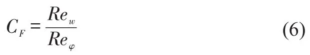
whereΩis the angular speed of disc.The flow coefficientCFis defined by Eq.(6).
Thenon-dimensionalpressurecoefficientCpisdefinedby:

wherep2is the local static pressure in the annulus,andis the averaged static pressure in the annulus over one pitch,ρis the density of fluid on the stator surface atr/b=0.993.

Φis a non-dimensional sealing parameter to quantify the flow rate of the seal flow.
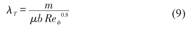
The flow state near the free disc face is determined by the turbulence flow coefficientλT.

βVis swirl ratio,andϕis tangential component of velocity.The concentration effectivenessεcis defined as:

wherecois the CO2concentration of sealing flow at the inlet of the system,cais the concentration of CO2of main flow path andcsis the concentration of CO2at determined points on the stator surface.There is no ingestion whenεcis 1.The seal effectivenessεis given by Eq.(12):

whereTmainis the inlet total temperature of the flowpath,andTlocalis the temperature of monitor point(P1 and P2)at the stator disc,ε13corresponds to the seal effectiveness in monitor point P1,andε23corresponds to the seal effectiveness in monitor point P2.Tseal is the temperature of the sealant flow at high radius of the rotor disc considered windage.The aircooling aerodynamic efficiencyηis defined as Eq.(13)[30-31]:

whereC1is the average velocity of mixed gas at the outlet surface(Z/S=0.75)in the main flow path.GΓis the mass flow rate of the mainstream airflow,GBiis the mass flow rate of the seal flow.Cais the averaged velocity of the mainstreamatthesurface(Z/S=0.25)inthemainflowpath,Coisthe averaged velocity of seal flow at the rotating surface(r/b=1).
In the test[13-14],CO2was used as the tracer gas for measurement of concentration to predict seal effectiveness.In the numerical calculation,the additional variable approach is used to predict the seal effectiveness.

Whereϕis the concentration of the tracer gas,Dϕis the Kinetic energy diffusion coefficient.The value ofDϕused for numerical calculation is 2.86 048×10-5m2/s.
1.3 Validation results
The numerical predicted swirl ratioβalong the monitor line(Z/S=0.25),the pressure coefficientCpat 1 mm downstream of the trailing edge of the vane in the annulus over one pitch,and the concentration effectiveness at monitor locationB(r/b=0.958)based on the gas concentration measurements are compared with the published experimental results[9].
Figure 5 shows the validation results of swirl ratioλT.The predicted result of configuration A is better than for configuration B to capture the flow characteristics in the turbine cavity and the position of the source region.Figure 6 shows the validation results for the flow coefficientCpin the annulus over one pitch of configuration A.The position of pressure measurement is 1 mm downstream of the trailing edge of the vane on the endwall of the stator disc,andθis the non-dimensional vane pitch.It can be seen that the numerical accurately predicts the asymmetric pressure distribution in the mainstream.
We also compare the predicted concentration effectiveness with the experimental results.CO2is used as a tracer gas to obtain a seal effectiveness based on the CO2concentration.The concentration of CO2at the monitor point on the stator disc(r/b=0.958)is predicted to estimate the effect of the mass flow rate of sealing flow on the rim seal effectiveness according to Eq.11.Numerical results of radial distribution of concentration rim seal effectiveness are also compared with the experimental data[9].As shown in Fig.6(b),the profile calculated by using the conjugate method is in good agreement with that measured in the test.

Fig.5 Validation results for the swirl ratio

Fig.6 Validation of the flow path boundary condition and the concentration effectiveness of the rim seal
2 Prediction Under Actual Working Conditions
2.1 Rim seal configurations
In modern gas turbines,the real rim seal configuration is more complex than the axial-clearance rim seal.Typical rim seal geometries include single clearance rim seal such as axial-clearance and radial-clearance rim seal and also double clearance rim seals such as a radial-axial clearance rim seal,double axial-clearance rim seal,and double-radial clearance rim seal.For the three most typical rim seal configurations,i.e.,axial-clearance,radial-clearance,and radial-axial clearance simulations are performed in this paper to show the effect of the rim seal configuration on hot gas ingestion and egress behavior of the purge flow for actual working conditions of the gas turbine.
Figure 7 shows the geometry of the axial-clearance rim seal,radial-clearance rim seal,and radial-axial clearance rim seal.Table 3 summarizes the geometry parameters of all three rim seal configurations.
2.2 Working Conditions
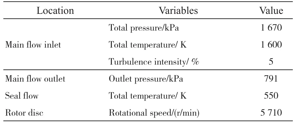
Actual working conditions of gas turbine are set for simulation,as shown in Table 4 and 5.Inlet total pressure of main flow is 1 670 kPa,total temperature is 1 600 K,and outlet pressure is 791 kPa.Inlet total temperature of sealant flow is 550 K,and the normalized sealant flow rateΦis a range from 0.007 05 to 0.169 2.
Rotating speed of rotor disc and blade is 5 710 rpm.Inlet Reynolds number isRew=4.66×10⁶,and rotational Reynolds number isReφ=6.5×10⁶,and then flow coefficient CF is approximately to 0.716 9.Fluid is set as ideal gas,and the specific heat capacity of hot gas is defined as polynomial of temperature:

wherea0is 957.110 256,a1is 0.236 523 4,anda2is 5.141 114×10-6,anda3is-3.391 744 6×10⁻⁹,anda4is-6.092 964 6×10-12[31].For CHT solid regions,the material of solid is superalloy.Its density is 8.32 g/cm3.Thermal conductivity of solid is set for a liner function of temperature asλs=0.023 3T-5.502 8(W/m·K),and the specific heat capacity of solid is defined in accordance with polynomial ofCs=0.000 7T2-0.493 5T+227.81(J/kg·K).The Young modulusEXof solid is 2.0×1 011N/m2,and the Poisson ratio PRXY of solid is 0.31.
2.3 Grids Independency and Turbulence Model
Figure 8 represents a schematic diagram of the grids for the three types of rim seals.Grids of fluid and solid domains are individually generated by commercial program ANSYS ICEM CFD.Grids near the wall surface,trailing edge and leading edge of guide vane,as well rim seal clearances are refined.
Table 6 summarizes the mesh details for the grid independence verification.For the axial-clearance rim seal,i.e.,No.1 to No.3,both fluid regions and CHT solid regions are unstructured grids.Grids No.4 to No.6 are high quality structured computational grids for the flowpath and rim cavity domains,while the CHT solid regions are unstructured grids.Comparisons of the flow path boundary conditions with these six grids are shown in Fig.9 for a non-dimensional sealing mass flow rate of 0.028 2,and a rotational speed of 5 710 rpm.
The grid for the whole computational domain comprises 3.359 million elements,where the fluid domain grid comprises 2.861 million elements,and the grid for the solid domain comprises 0.498 million elements.The Y-plus value of the most area of the rotor and stator discs surfaces is in the range of 2 to 4.Similar verifications are also performed for the other two rim seal configurations.Finally,the grid for radialclearance rim seal comprises 6.034 million elements,and the grid for the radial-axial clearance rim seal comprises 6.317 million elements.Figure 10 shows all the monitor positions in the following section.Three turbo faces with differentθ(θ=0.14,0.35,and 0.78)are placed.In the turbo face withθof 0.35,two monitor points and two monitor lines are performed.Monitor pointP2is in the high radius position of the turbine cavity,and monitor pointP1is in the mid radius position of the turbine cavity.A horizontal line and a vertical line are performed in the turbine cavity.For the endwall region,revolution surface 1 is performed in the radius of 0.195m,and revolution surface 2 is performed in the radius of 0.19m.

Tab.3 Geometry parameters of the all three rim seal configurations
Tab.4 Boundary conditions for the conjugate heat transfer calculation
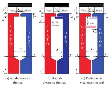
Fig.7 Turbine rim seals and its geometry parameters

Tab.5 Simulation parameters

Fig.8 Computational grids for the three rim seals configurations

Tab.6 Grid details of the three rim seal configurations

Fig.9 Computational grids verification for flowpath boundary condition

Fig.10 Monitoring points and surfaces in turbine cavity and rim clearance
3 Numerical Results And Discussion
3.1 Seal effectiveness
The seal effectiveness of the three rim seal configurations are compared first.The monitoring pointP1is at the mid-radius height of stator disc atr/b=0.789 and the monitoringP2is at the high radius height of stator disc atr/b=0.958.Figure 11 shows the comparison of seal effectiveness of three rim seal types.For both rim seal types,its seal effectiveness increases with the increase in mass flow rate of cooling air.
Figure 11(a)shows the comparison of seal effectiveness of three rim seal types at disc mid-radius height such as locationP1.Seal effectiveness increases with the increase in mass flow rate of cooling air.The seal effectiveness of the radial-axial clearance rim seal is the highest,and the minimum mass flow rate for seal of the radial-axial clearance rim seal is 0.857 times of radial-clearance rim seal.When the seal effectiveness of radial-axial clearance rim seal reaches 1,the seal effectiveness of axial-clearance rim seal is 0.943.For the radial-axial clearance rim seal,the seal effectiveness increases with the increase in mass flow rate of cooling air,while the seal effectiveness increases from 0.924 to 1 by using 3.6 times of mass flow rate of cooling air to increase seal effectiveness from 0.181 to 0.924.
Figure 11(b)shows the comparison of seal effectiveness of three rim seal configurations atP2.Effect of increasing cooling air on seal effectiveness of all three seal configu-rations is similar.In local sealed conditions,the seal effectiveness at high radius height is lower than that at disc midradius height because of hot gas ingestion from flow path.For radial-axial clearance rim seal,inner seal ring is helpful to prevent the hot gas ingestion into mid radius regions.
3.2 Cavity flow and heat transfer characteristics
Asymmetric pressure distribution in external annulus clearance causes external induced ingress(EI),and the pumping effect of rotor disc causes the rotational induced ingress(RI)[8-16,32].Swirl ratio beta is one of the most important non-dimensional parameters to describe turbine cavity flow.Figure 12 compares the swirl ratios of turbine cavities corresponding to the three rim seal configurations.The monitor line is located at 3/4 width of cavity away from rotating disc.Results show that the inner seal ring of radial-axial clearance rim seal apparently divides the tangential velocity component of whole cavity into two parts.For radial-clearance and radial-axial clearance rim seal configurations,the tangential velocity have a strongly vibration science the monitor points at the high radius are close to the endwall of disc.
The pumping effect of rotor disc results in the swirl ratio increases with the radius.Near endwall region,high tangential velocity component of fluid is caused by hot gas leakage from the main flow path,and the ingress behavior of hot gas is improved with the increase in mass flow rate of cooling air.When the mass flow rate of cooling air of the turbine cavity is very small(Φ=0.028 2 condition of Fig.12),since the mass flow rate of radial inflow is much smaller than the entrained flow rate of rotational disc,a large amount of gas flows along the surface of static disc to the source region in the lower radius,and eventually be sucked to the rotor side as a supplement,resulting in an increase in the tangential velocity of turbine cavity flow.The swirl ratio decreases with the increase in mass flow rate of cooling air(Φ=0.056 3 condition of Fig.12).When the entrainment flow of rotor disc surface is totally provided by the radial inflow of cooling air,it is no longer to extract the fluid from the surface of static disc side as a supplement.Thus,the reduced pump effect of rotor disc results in a lower tangential velocity component and swirl ratio of turbine cavity.
Figure 13 summarizes the tangential velocity distribution along the axial direction at the mid radius of turbine cavity.The tangential velocity component is zero near static disc side.The maximum value of tangential velocity is on the surface of rotor disc.Increasing mass flow rate of cooling air weakens the pumping effect of rotor disc,and then decreases the tangential velocity of turbine cavity flow.The tangential velocity in monitor line in turbine cavity with axial-clearance rim seal is consistent with that of radial-clearance rim seal.The tangential velocity in monitor line in turbine cavity with radial-axial clearance rim seal is the smallest due to the existence of inner seal ring.
Figure 14 summarizes the radial velocity distribution along the axial direction at the mid radius of turbine cavity.When the mass flow rate of cooling air of the turbine cavity(Φ=0.028 2)is smaller than the entrained flow rate of rotational disc,fluid near static disc flows to the radius of rotor disc as a supplement.The radial velocity near rotor disc is positive and the radial velocity near static disc is negative.With the increase in mass flow rate of cooling air,the positive radial velocity near rotor disc region increases significantly,and the negative radial velocity near static disc region increases slightly as a result of the reduced pump effect of rotor disc.For radial-axial clearance rim seal,inner seal ring limits the affect region of ingestion gas and protects the inner cavity from ingestion gas.At the same time,backflow of cooling air caused by inner seal ring directly increases the negative radial velocity near static disc region.
Figure 15 shows the comparisons of the temperature distributions in the turbine cavity and discs(θ=0.14)of three rim seal configurations.It can be seen that in Fig.15,the temperature of turbine disc at high radius is higher than that at disc mid-radius height,the temperature of stator disc is higher than that of rotor disc.The cooling air firstly cools the low radius region of rotor disc,and then the cooling air flows to high radius of rotor disc with windgae temperature rise.The thermal conduction of annulus flow path and hot gas ingestion through rim seal clearance together determine higher temperature distribution in Fig.15.When the hot gas can not be sealed in the high radius,rotational induced ingress increases the temperature stator disc.Increasing mass flow rate of cooling air increases rim seal effectiveness,and reduces hot gas ingestion and ingress depth,along with lower temperature of turbine discs.

Fig.11 Comparison of seal effectiveness of three rim seal configurations

Fig.12 Effect of rim seal structure on swirl ratio of cavity flow

Fig.13 Effect of rim seal structure on tangential velocity of cavity flow

Fig.14 Effect of the rim seal geometry on the radial velocity in the cavity
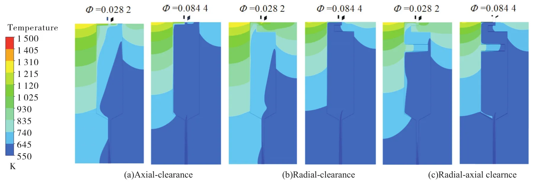
Fig.15 Effect of rim seal structure on temperature distribution of turbine cavity and disc(θ=0.14)
For axial-clearance and radial-clearance rim seals,flow characteristics in cavity flow are consistent,that is,the seal ring in the high radius only affects the rim seal region.Radial-clearance avoids facing to mainstream directly.For radialaxial clearance rim seal,inner seal ring is the decisive factor that causes the difference in flow characteristics inside and outside the inner ring.Inner seal ring divides the whole turbine cavity,greatly decreases the effect of ingestion gas on cavity flow,and reduces the tangential velocity component of inner cavity flow.Radial-axial clearance rim seal keeps the advantages of radial-clearance one,further reducing the temperature of rotor and stator discs.
3.3 Flow and heat transfer characteristics in clearance flow
Figure 16 shows the effect of mass flow rate of cooling air on the averaged temperature of rim seal clearance.A large amount of purge flow significantly decreases temperature of mainstream and reduces the output power of turbine.Under the minimum seal flow rate working condition corresponding to the radial-axial clearance rim seal,the averaged temperature of surface 1 of radial-axial clearance rim seal is 1.3 times that of axial-clearance rim seal.In other words,radial-clearance in the high radius reduces the temperature decline of mainstream caused by purge flow when compared to the axial-clearance rim seal.

Fig.16 Effect of purge flow on the temperature of mainstream with different rim seal configurations
The comparison of air-cooling aerodynamic efficiency reveals the difference in containment effect of different rim seal configurations on purge flow.Figure 17 compares the aerodynamic efficiency and rim seal effectiveness of rim seal configurations.Increasing mass flow rate of cooling air decreases the hot gas ingestion into rim cavity,and increases the rim seal effectiveness.At the same time,a large amount of purge flow increases momentum loss of mainstream,and decreases the aerodynamic efficiency.For the axial-clearance rim seal,large loss of average velocity of mixed gas at the outlet surface(Z/S=0.75)mainly results in large loss in aerodynamic performance.Negative effect of purge flow on mainstream is significantly improved by the radial-axial clearance rim seal.Corresponding to respectiveΦminof each seal,air-cooling aerodynamic efficiency of the radial-axial clearance rim seal is 23.71%higher than that of the axialclearance rim seal,and 12.79%higher than that of the radialclearance rim seal.
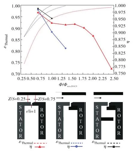
Fig.17 Comparison of air-cooling aerodynamic efficiency and rim seal effectiveness
4 Conclusions
Performance of radial-axial clearance rim seal under realistic working condition is compared with that of axial-clearance rim seal and radial-clearance rim seal.Effect of rim seal structure on flow and heat transfer characteristics in rotor-stator system,mainstream performance penalty are discussed in this paper.The main conclusions are as follows:
1)Seal effectiveness of three rim seal configurations are increased with the increase in the amount of cooling air.The seal effectiveness at high radius is lower than that at disc mid-radius height.Under the same working condition of the flow rate of cooling air,the radial clearance at high radius has better sealing performance than the axial one.The inner seal ring mounted at disc mid-radius height of stator disc further increases the seal effectiveness of inner cavity region.
2)According to the single clearance rim seal configurations,the flow characteristics in cavity are consistent due to the pumping effect of rotor disc,the seal ring in the high radius only affects the rim seal region.Radial-clearance shows better performance in decreasing the amount of ingestion air,and significantly improving the temperature distribution of turbine discs.The radial-axial clearance rim seal keeps the advantages of radial-clearance one,further reducing the negative effect of ingestion gas on temperature of rotor and stator discs.
3)There is a contradiction between the air-cooling aerodynamic efficiency and the cooling effectiveness.With the increase of the cooling air,purge flow obviously increases the aerodynamic loss in mainstream and pressure loss in guide vane.Corresponding to respectiveΦminof each seal,effect of purge flow with radial-axial clearance rim seal on the mainstream performance penalty is the smallest in three seal types.The air-cooling aerodynamic efficiency in radialaxial clearance rim seal is 23.71%higher than the axial-clearance rim seal,and 12.79%higher than the radial-clearance rim seal.
杂志排行

风机技术的其它文章
- Unsteady Behavior of Tip Leakage Vortex in an Axial Compressor with Different Rotor Tip-gap Sizes Using DDES*
- Evaluation of Helium Xenon Gas Mixture as Working Fluid in Highly Loaded Axial Compressor*
- Remarks on Time-Accurate Adjoint of Quasi-One-Dimensional Euler Equations*
- Multi-objective Optimization Design of a Centrifugal Impeller*
- 板式无蜗壳离心风机内部流动分析及分流叶片影响*
- 多翼离心风机叶片的结构改型设计与试验研究