Multi-objective Optimization Design of a Centrifugal Impeller*
2019-06-18JileiWangJinguangYangYanLiuTianchenZhang
Ji-lei WangJin-guang YangYan LiuTian-chen Zhang
(School of Energy and Power,University of Technology,Dalian,China)
Abstract:A parameterization method of radial turbomachinery is presented in this paper. Based on this method, a computing code is developed . An optimization platform for a centrifugal impeller is constructed by integrating three modules of the optimization process, namely parameterization, mesh generation and numerical calculation. The commercial optimization software Isight and computational fluid dynamics software NUMECAare used in the present study. The Krain impeller is taken as an example to validate the optimization system, eights parameters that affect the shape of the mean camber line are selected as design variables, and isentropic efficiency and total pressure ratio are set as objective functions. The impeller with better performance is obtained by means of optimization. Results demonstrate the feasibility of the parameterization method and the validity of the integrated optimization platform.
Keywords:Centrifugal impeller,Parameterization,Optimization
βblade metal angle
m'normalized streamwise coordinate
θnormalized circumferential coordinate
y(x) unknown actual value
εrandom error
Vmmeridional velocity
DOE design of experiments
ASA adaptive simulated annealing
BD baseline design
OPT optimized design
0 Introduction
The centrifugal compressor has the advantages of high pressure ratio per stage,compact structure,wide working range and high efficiency in the case of small mass flow,Hence it is widely used in turbochargers,aero-engine auxiliary power systems and micro gas turbines etc.A centrifugal impeller is one of the core components of these machines,and its performance has great influence on the whole machine.It is a challenging task to design a high pressure ratio centrifugal impeller work in a wide flow conditions with high performance[1].Essentially,the aerodynamic design of impellers is a 3D multi-objective issue.In addition,the phenomenon involved in the impeller passage is fairly complex,many design variables should be considered.There is no analytical expression existed between design variables and performance objectives,the computational fluid dynamics(CFD)tool is usually employed for the performance evaluation of designs.However,the full 3D CFD evaluation is usually very time-consuming,so the design variables should be reduced as much as possible.Overall,the design of high pressure ratio impeller is a typical high dimensional,computationally expensive work.
In order to acquire better designs and reduce the design cost,automated design optimization method has gained a widespread attention in recent years.Luo et al.[2]conducted the automated design optimization of a typical axial transonic compressor blade using a modified differential evolutionary algorithm.By integrating a genetic algorithm with artificial neutron network,3D design optimization of a centrifugal impeller,as well as a transonic axial blade[4],are carried out by Verstraete et al[3].
In this paper,commercial optimization software Isight is used to integrate the optimization process,and an integrated optimization design platform for centrifugal impeller is preliminarily built.The Krain impeller is optimized to validate the platform.The subsequent sections are organized as follows:First,Parameterization method and baseline impeller model are introduced.Second,an automated 3D multi-objective design optimization platform is shown.Using the platform,multi-objective aerodynamic design optimization of the Krain impeller is carried out for maximizing isentropic efficiency and total pressure ratio.Finally,some conclusions are summarized.
1 Parameterization Method and Design Models
1.1 Parameterization method
The design space of an optimization process is determined by the parameterization method;thereby,the 3D parameterization of the impeller is an important issue for design optimization.Here,a 3D parameterization method is presented.Figure 1 presents the parameterization process which can be described as follows:
Step 1:The parameterization of endwall channel is divided into two meridian lines,ie.the hub and shroud.The meridian lines are constructed with a cubic NURBS[5-7]curve of five control points(see Fig 1(a)),where,A,J and E,F are used to fix the inlet and outlet of the impeller respectively,and B,C and D points are used to control the shape of the shroud,and I,H and G for the hub.
Step 2:The mean camber line is obtained by integrating the blade metal angle along meridian direction.The distribution of blade metal angle is fitted by NURBS curves of four control points(see Fig 1(b)),wherein,the points at the two ends are fixed,the rest of the points are active control points.The thickness distribution is specified by NURBS curves with five control points(see Fig 1(c)).
Step 3:The pressure or suction side of section profiles are defined by adding the thickness distribution to the camber line.Thus,a reshaped section profile is obtained(see Fig 1(d)).
Step 4:After finishing the impeller section design,a transformation of the geometry into 3D coordinate has to be done.Three dimensional blade can be stacked from shroud to hub along a straight line at the trailing edge.(see Fig 1(e)).

Fig.1 Parameterization of(a)end walls,(b)blade metal angle,(c)half thickness distribution,(d)2D blade section profile,(e)3D blade
1.2 Design model and optimization parameters
The Krain impeller[8]is a semi-open impeller designed by Dr.Krain of German Aerospace Institute in 1981.Basic information of the impeller can be found in Table 1.The impeller geometry and experimental data are well documented,so it is widely used to validate numerical methods and be optimized a baseline model[9-14].

Tab.1 The parameters of the krain impeller

Fig.2 Design variables for optimization process
2 Basis of Optimization Theory
2.1 Design of experiments
The design of experiments(DOE)method is a branch of mathematical statistics,which provides a reasonable and effective method to obtain data information.The main functions of DOE include determining the design variables that influence the design,determining the optimal combination between the design variables,establishing the approximate model,and improving the design robustness.There are many DOE algorithms,and the one chosen here is the Latin Hypercube method,which has an effective capacity of space filling and nonlinear response filling.
2.2 Approximate model
The approximate model is a method to find the response relationship between the input and output variables by establishing a mathematical model.In recent years,the approximate model method has been widely applied to the optimization design.Its main advantages include the following three aspects:1)establish the empirical formula for the relationship between the input and the output variables;2)reduce the calculation time of numerical simulation;3)smoothing the response function is helpful to find the global optimization value.The response relationship of the approximate model between the input variable and the output variable is described in the following formula:

2.3 Optimization algorithm
The computer numerical optimization has been developing rapidly in recent years.Traditional optimization methods can be divided into two main categories:the direct method and indirect method.However,the mapping relationship between design variables and objective function is more nonlinear and high dimensional,so the designers always try to design optimization methods inspiring by knowledge of other disciplines,and many modern optimization method is put forward,as genetic algorithm,simulated annealing method,artificial neural network,etc.Those methods applied in many engineering fields as the high capability of global optimization.The simulated annealing(SA)method,combines the optimization problem with the thermal equilibrium problems in statistical mechanics analogy.The adaptive simulated annealing(ASA)algorithm used in this paper is an improved method of the traditional SA algorithm.It has the advantages of being able to deal with any system and target function and explore the global optimization solution effectively.
3 Multi-objective Optimization
3.1 Design optimization platform
To combine optimization algorithm with CFD calculation,the first step is to generate a sample database.However,for CFD calculation,the production of each sample needs to be generated by procedures including geometric model construction,mesh generation,and numerical solution etc.,the process involves lots of repetitive work.To integrate the whole optimization flowchart,the commercial optimization software Isight is adopted.With the help of grid generation module Autogrid and flow solver Fine/Turbo module of the commercial CFD software NUMECA,an automated design and optimization process is finally realized,as shown in the Fig.3.

Fig.3 Design optimization platform
3.2 Optimization design process
Through this optimization design process,the isentropic efficiency and total pressure ratio are set as objective functions.The whole optimization process include the following steps:(1)DOE;(2)approximate model;(3)numerical optimization.Firstly,the design variables were analyzed by using the Latin hypercube method.Then,according to the sample database of the experimental design,the approximate model of the mapping relationship between the design variables and the target function is established by using the fourth-order response surface regression analysis method.Finally,the approximate model is iteratively iterated and updated to explore the global optimal solution through the ASA algorithm.The flow chart of the multi-objective design optimization is shown in Fig.4,the specific steps are as follows:
Step 1:Parameterize the design model and select the design variables.
The real life and spirit of this magical elf lives forever in your heart, my heart, Mom’s heart and in the hearts and minds of all people who believe in the joy that giving to others brings
Step 2:The sample database was generated using the DOE method,and the corresponding response value of each sample was obtained by CFD calculation.The error analysis is carried out to ensure the reliability of the results.
Step 3:According to the sample database,the approximate model of the mapping relation between the design variables and the target function is established by using the fourth-order response surface regression analysis method.
Step 4:The ASA algorithm is used to search the global optimal solution,and the optimization results are verified by CFD calculation.

Fig.4 Flow chart of multi-objective design optimization
4 Optimization Results and Discussion
4.1 Optimization history and optimized blade geometry
During the optimization process,10 central processing units(CPUs)are used for parallel computing.As mentioned above,4 control points 8 parameters are selected as design variables,which generate 300 DOE samples to construct the approximate model,and each sample takes about 50 minutes for CFD calculation.To obtain the optimal solution of the object function,10,000 CFD calculations are run for searching the global optimal solution.It takes about 15 days to complete the whole optimization process.The Pareto front of the multi-objective optimization can be seen in Fig.5.As the control points mainly affect the mean camber line,the blade tip and root sections are compared between the optimized and original ones,which is shown in Fig.6.It can be seen from the Fig.6(a)that the root section of the optimized result is basically the same as that of the baseline,only the blade metal angle is changed at the leading edge.The tip section(Fig.6(b))of the optimized result is of more difference from that of the baseline.

Fig.5 Solution space of the Krain impeller optimization

Fig.6 Baseline and optimized geometry
4.2 Aerodynamic optimization analysis
In order to analyze the advantage of the optimized impeller,overall performance is compared between the optimization and the baseline geometry,and is listed in Table 2.It is found that an approximate 1-point is gained in isentropic efficiency.Then the flow fields of baseline impeller and optimized impeller at design condition are compared.The meridional velocity distribution is shown in Fig.7,and the relative Mach number contour near the shroud is shown in Fig.8.

Fig.7 Meridional velocity distribution at meridian plane

Tab.2 Performance comparison at optimization point

Fig.8 Relative Mach Number at 95%span of blade section

Fig.9 Entropy distributions at streamwise sections and limiting streamlines near the wall

Fig.10 Entropy counters at the blade pressure surface
According to Fig.7,the meridional velocity distribution at pitch averaged meridian plane of the two models are almost the same,but the baseline impeller has a low speed zone at the impeller outlet,the distribution of the meridional velocity is more uniform,causing a better flow filed in the diffuser after optimization.
From Fig.8,it can be seen that,compared with baseline design,the low speed area of optimized design at rear part of the impeller is obviously smaller than the baseline.
The limiting streamlines and entropy of the full blade are shown in Fig.9.After optimization,the entropy distribution at streamwise sections is improved obviously at the impeller outlet,the involved high loss area is smaller,and the largest entropy values of high loss at outlet of hub side are also reduced.What's more,the limiting streamlines at the impeller inlet of the optimized one shows a reduced secondary flow phenomenon,which is helpful to reduce the leakage flow interactions between neighboring passages and make a homogeneous flow at the impeller outlet.Although the entropy at the blade shroud is slightly increased,the entropy counter of the blade pressure surface does show improvement,as is shown in Fig.10.
Figure 11 compares the behavior of the impellers by varying their mass flow.Both the isentropic efficiency and the total pressure ratio of optimized design are increased over the whole working-range.On a whole,the performance of optimized design is greatly improved at both design and off-design conditions.
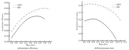
Fig.11 Off-design performance comparison
5 Conclusions
An automated multi-objective design optimization platform is preliminarily constructed by integrating a parameterization modeling,DOE,approximate model and numerical optimization.Multi-objective design optimization is carried out for a typical centrifugal impeller,the Krain impeller.Some conclusions are obtained:
1)It is a feasible parameterization method to control the meridian line of the impeller,the blade metal angle and the thickness distribution with NURBS curves to complete the geometric modeling.
2)The approximate model of the mapping relation between the design variables and the objective function generating from the sample database of DOE can effectively shorten the calculation time.
3)For the 3D multi-objective aerodynamic design optimization of the Krain impeller,the optimization is successfully run to maximize the isentropic efficiency and the total pressure ratio.The isentropic efficiency is nearly 1%higher than baseline geometry at design condition and the total pressure ratio is also improved obviously.
4)With above work,the effectiveness and feasibility of the automated optimization platform is demonstrated.
杂志排行

风机技术的其它文章
- Unsteady Behavior of Tip Leakage Vortex in an Axial Compressor with Different Rotor Tip-gap Sizes Using DDES*
- Evaluation of Helium Xenon Gas Mixture as Working Fluid in Highly Loaded Axial Compressor*
- Remarks on Time-Accurate Adjoint of Quasi-One-Dimensional Euler Equations*
- 板式无蜗壳离心风机内部流动分析及分流叶片影响*
- 多翼离心风机叶片的结构改型设计与试验研究
- Effect of the Rim Seal Configurations on the Hot Gas Ingestion into the Rotor-stator Cavity*