An Experiment on Cavitating Flow in Rocket Engine Inducer
2019-06-04LILongxianDINGZhenxiaoZHOULiangWUYuzhen
LI Longxian,DING Zhenxiao,ZHOU Liang,WU Yuzhen
1.Beijing Aerospace Propulsion Institute,Beijing 100076,P.R.China;2.School of Medicine Shanghai Jiao Tong University,Shanghai 200025,P.R.China
Abstract: An experiment for rocket engine inducer cavitating flow is conducted on a new experimental platform. The experiment platform,using water as working medium,can be used to investigate the steady and unsteady flows of cavitating and noncavitating turbopumps. The experimental platform is designed as a flexible and versatile apparatus for any kind of fluid dynamic phenomena relating to high performance liquid rocket engine turbopumps. Design details for the platform is introduced. Various extend of cavitation images and dynamic pressure impulse are obtained,which provides a reference for cavitating flow study in rocket engine inducer.
Key wor ds: rocket engine turbopump;inducer;experiment research apparatus;cavitation images;dynamic pressure
0 Introduction
Propellant feed turbopumps are a crucial component of all primary propulsion concepts powered by liquid propellant rocket engines because of the severe limitations associated with the design of high power density,dynamically stable machines meeting the extremely demanding suction,pumping and reliability requirements of space transportation systems. Cavitation is the major source of degradation of the suction performance,reliability,power density and useful life of turbopumps,and the cause of other equally undesirable effects such as the reduction of the overall efficiency and the drastic increase of the noise generation[1]. Even more importantly for space applications,cavitation can provide necessary flow excitation,compliance and load-dependence for triggering dangerous rotor dynamic and fluid mechanic instabilities of the turbopump,or even,through the coupling with thrust generation,of the entire propulsion system.
Currently,the theory of cavitation mechanism is still far from mature. Numerical simulations for vapour-liquid two-phase cavitation still lack of universal turbulence and cavitation model. Theoretical analysis and numerical calculation can only play the role of assistant measures. Controllable experiment and elaborate measurement are two main methods for cavitation research. Experimental investigation for inducer cavitation includes flow filed parameter measurement and flow filed optics measurement[2],where optics measurement,called the visualization observation,is an important method. It is impossible to make any progress for advanced inducer research without direct flow visualization. The ability to look into the flow field directly and observe the characteristic of the cavitating flow is extremely important[3].
To comprehend cavitation flow field and instability mechanism stimulated by cavitation in inducers,high speed visualization combined with pressure impulse was used to observe cavitation flow field. In this paper,the experimental facility constructing process,test procedure and result data processing was introduced in detail.
1 Experiment
The experiments facility is shown in Fig.1,encompassing three major parts[4]:(1)Pump external characteristic experimental system,including hydraulic system(water tank,make-up pump,vacuum and pressure pipeline,filter,cooler,experiment pipeline etc.),power system (motor,gearbox,electronic controlling equipment),and pump external parameter measurement system(to measure inlet and out pressures,temperature,flux,and rotating speed,etc.).(2)Dynamic pressure measurement system,which is used to realize inducer tip gap pressure impulse characteristic measurements[5],including dynamic pressure sensor,signal exchanger,data collecting and recording equipment,computer,etc.(3)Flow filed visualization experiment system,including high speed camera,cable,imagine acquiring and recording system,computer,etc.
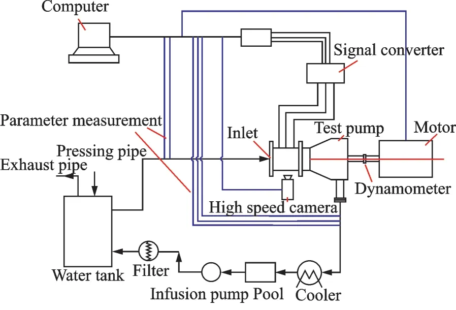
Fig.1 Experimental platform
1.1 Design of experimental segment
The experimental segment was designed based on an inducer-centrifugal pump assembly,including pump case,inducer,guide vane,and impeller,etc.The experimental segment construction,mainly based on the reform of assembly case,was modified on the part of inlet and inducer[6],as shown in Fig.2. The new case was manipulated by welding prototype case and a particular flange. A part of polymethyl methacrylate tube was clamped by four long bolts between inlet segment and pump case.The polymethyl methacrylate tube plays the roles of both observation window and sensor installation carrier,which should possess the characteristics of high strength and high light transparency[7].
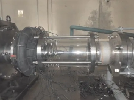
Fig.2 Redesigned model of experimental segment
1.2 Design of inlet pipe
To connect the experimental segment and pipe,it is necessary to redesign the inlet pipe. The inlet pipe component assembly is show in Fig.3. Considering fabrication for the pipe installation,a bellows was installed between the connection pipe and inlet flange,which adjusted space during the process of pipe installation.
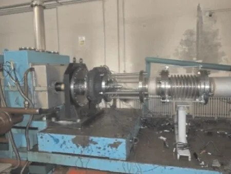
Fig.3 Redesigned pipe assembly
1.3 Dynamic pressure measurement
Dynamic pressure measurement is an independent system during the experimental process,which is used to collect the inducer tip high frequency pressure impulse,including dynamic pressure sensor,cable,power unit,and signal recorder,etc. The dynamic pressure sensor,with frequency response as high as 2 000 k Hz,was selected as small-sized high frequency response dynamic pressure sensor. Table 1 shows the parameters of dynamic pressure sensor and Fig.4 shows the physical photo and sensor size.
1.4 Distribution of measurement points
The 24 pressure sensors were distributed on the observation case,which were used to collect the pressure impulse both along axial direction and cir-cumferential direction. The sensors were divided into three groups with eight sensors each. The first group located in the front of the test inducer leading edge 8 mm to capture inlet cavitation and vortex.The second group located behind the inducer leading edge 27 mm to capture the middle cavitation pressure impulse. While the third group located behind the inducer leading edge 62 mm to capture the inducer outlet pressure impulse.
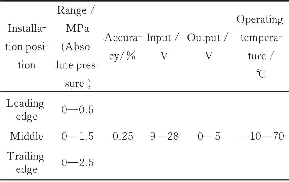
Table 1 Dynamic pressure sensor parameters
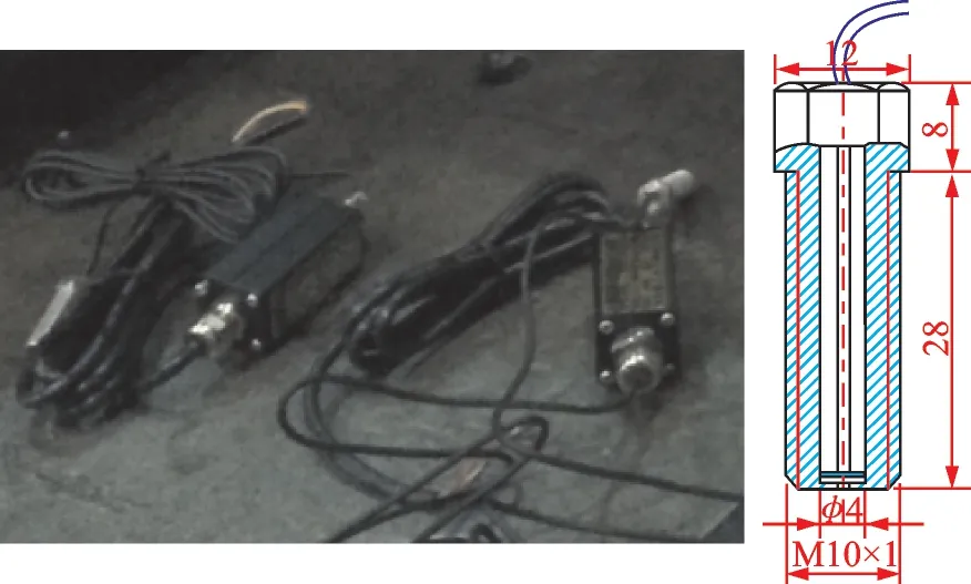
Fig.4 Dynamic pressure sensor
1.5 Data recording equipment
Each channel for the sensor data transmission was pressure sensor with data recorder. The distributer provided power for 24 sensors with 5 V direct current uniformly.
The dynamic pressure signal was recorded by Necolet data recorder. There were 16 channels in each recorder. It required two recorders during experiment,containing 24 dynamic pressure channels.In addition,it is necessary to record rotate speed,torque,flux,inlet pressure,outlet pressure,ambient pressure,and camera synchronizing signal.
1.6 High speed camera
High speed camera is crucial for visualization in the experiment. The high speed camera(MotionXtra HG-XL)used in the experiment was a product having a record rate from 1 000 f/s to 100 000 f/s,with the maximum solution 1 504 pixel ×1 128 pixel.
1.7 Lighting equipment
The visualization experiment on inducer cavitation flow field,a kind of high speed imaging experiment,requires artificial lighting apparatus[8]. Since the exposure time for high speed imaging was extremely short,the exposure time for each image in this experiment was just 0.001 s. It is impossible to obtain clear image in such a short time frame without artificial lighting. Three lighting apparatuses were employed,including one halogen light(with power 1 000 W)and two fluorescent lamp(with power 200 W each),as shown in Fig.5.
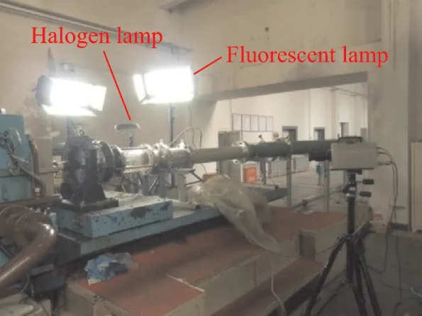
Fig.5 Artificial lighting apparatuses for visualization
1.8 Test inducer
The inducer used in this paper was a three-bladed inducer made of steel. It held a varying pitch helical geometry,with tip radius of 140 mm,leading edge angle of 5.5°,and trailing edge angle of 8°,as shown in Fig.6. The designed condition for the inducer was 18 000 r/min,with working medium of liquid oxygen. However,the rotating speed dropped to 3 000—4 000 r/min during experimental process,for obtaining clear cavitation images.
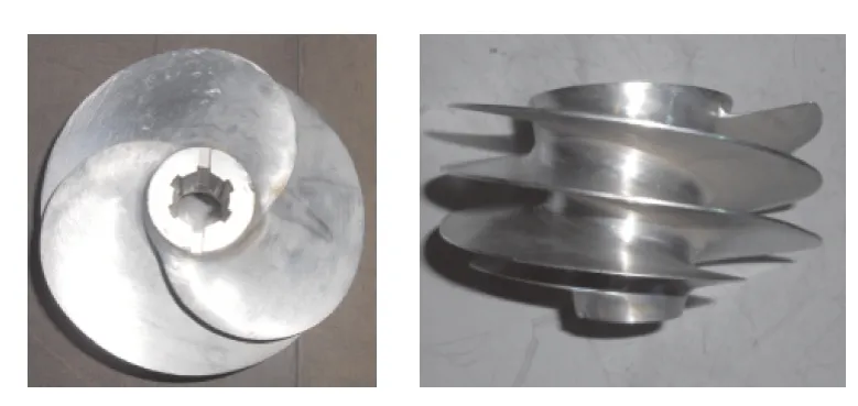
Fig.6 Test inducer
1.9 Experimental conditions
The experiment has been conducted by using water at room temperature as working medium.During the experimental process,the rotating speed of pump was kept constant,being 3 000 r / min or 4 000 r/min. The inlet absolute pressure dropped from 0.5 MPa to 0.002 MPa gradually. That is to say,the cavitation intensity developed from nascent to serious manually. Cavitation images and flow filed pressure impulse were recorded simultaneously.
2 Analyses
2.1 Algorithm for image processing
An image processing algorithm is developed to characterize the regions of the image where cavitation is present. Running the algorithm in Matlab allows automatic processing of movie frames taken by a high-speed camera. To identify the cavitation filed,the image subtraction method is employed[9]since the cavitation filed can be extracted by subtracting the non-cavitating images(Fig.7).
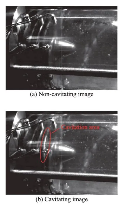
Fig.7 Cavitation image process program
2.2 Analyses of experimental results
The typical results obtained in the experiment with the inducer are reported[10-11]. The characteristic curves for the complete pump(inducer and centrifugal impeller)are presented in Fig.8. In particular,the correspondence behavior of the work coefficient isand cavitation number is σ=,where pt2and pt1are the inducer outlet and the inlet total pressures,respectively,ρ the liquid working medium density,Ω the angular velocity,rT2the inducer blade tip radius,p1the inducer inlet press,and pvthe saturation pressure. As expected,the performance of the complete pump is influenced seriously by cavitation when σ ≤0.022.
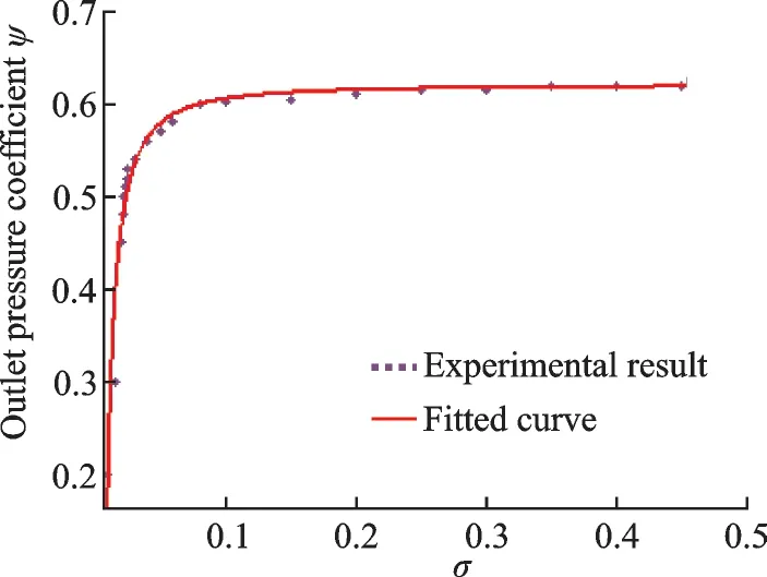
Fig.8 Outlet pressure coefficient changed with cavitation number
The cavitation image can be attained clearly via post-processing. The rotating speed was 4 000 r/min and the image record rate was 1 000 f/s during experiment. It can observed that the cavitation surface tend to increase when the cavitation number decreases. Cavitation area appears near the leading edge primarily,adhering to the blade suction side like a long sheet,as shown in Figs.9(a,b). The cavitation area separates from inducer blade when the cavitation number is less than a critical value. For the inducer in this paper,the critical cavitation number is 0.03.As the cavitation number decreases,cavitation area expends gradually,evolving from a long sheet to a wide area,which is called the cloud cavitation[14],as shown in Fig.9(c). Fig.9(d)shows a liquid-vapor two-phase flow,exhibiting serious cavitation turbulence. In this situation,the inducer works in a liquid-vapor two-phase environment,which leads to dramatic deterioration in work capability of the inducer.
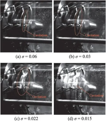
Fig.9 Flow field images during cavitation development
The experimental platform can obtain pressure signal synchronously,since there is a synchronous signal button between the parameter measurement system and the visualization system subsequently.The relationship between pressure impulse and cavitation image can be studied in depth. Fig.10 shows typical pressure signal under cavitation inception conditions of the inducer,showing the flow filed pressure fluctuating with various amplitude and similar period. It indicates that the cavitation flow field contains various kinds of pressure impulses. Fig.11 shows spectral analysis corresponding to the pressure signal,which suggests that the recurring frequency is 3,6 and 9 times of rotating speed frequency(fN). In addition,there is a low frequency peak value(f0)which can be easily found. The peak can be predicted as a signal of cavitation surge.
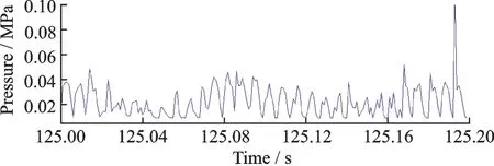
Fig.10 Typical pressure signal under cavitation inception conditions of the inducer(3 000 r/min,σ=0.03)
Surge and rotating cavitation in the turbopump can be readily detected in the experiment either by optical means or by monitoring the inlet pressure frequency spectral and flow rate to the inducer. In Fig.11(b),various pressure frequency multiplication can be observed clearly in this situation,which indicate that instability and turbulence increase dramatically as cloud cavitation occurs. Both cavitation image and flow field dynamic pressure can indicate flow instability.
As cavitation number decreases to a lower level,various pressure frequency multiplication disappears,with three times frequency left only. An example of the pressure spectrum at cavitation number σ=0.015 is displayed in Fig.11(c). The pressurization capability of inducer is weakened in radical cavitation environment,because most of flow field is occupied by vapor phase in this situation. Accordingly,dynamic pressure amplitude is reduced dramatically. A large number of characteristic frequency spectrum disappear.
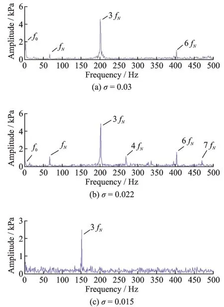
Fig.11 Frequency spectrum in various cavitation number during cavitation development
Fig.12 shows the three-dimensional frequency spectrum during cavitation development. Typical pressure impulse signal can be observed obviously when rotating cavitation occurred. Generally,it is a supper synchronous signal,about 1.1—1.4 times of rotating speed[15-16]. The test facility data acquisition includes low-pass anti-aliasing filter of adjustable cut-off frequency on all input channels for accurate numerical evaluation of the signal spectra. Discrimination of cavitation surge from rotating cavitation and other unsteady flow phenomena is readily and efficiently affected by cross-correlation of the inlet pressure and flow rate[17-18].
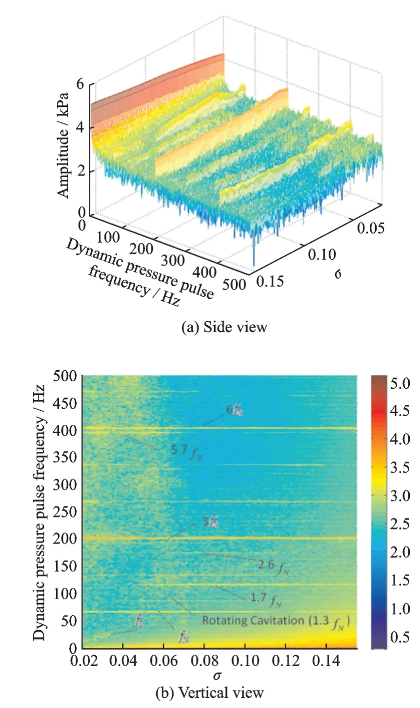
Fig.12 Three-dimensional frequency spectrum during cavitation development
3 Conclusions
The inducer cavitation experiment was performed based on a new experimental platform. The platform covers cavitation research for multifarious axial and radial flow turbopumps typically used in rocket propellant feed system. The experimental platform can obtain clear cavitation images and pressure impulse signal effectively,which provides us a new method to study inducer cavitation,including cavitation bubble born,development and collapse.
The experimental platform represents an effective support for turbopump design,which provides a novel approach for investigating cavitation characteristics of turbopump inducer in deepth. During the experimental process,cavitation dynamic process and dynamic pressure signal can be obtained clearly.Ultimately,it will give the designers of high performance turbopumps a deep insight into the development of dangerous flow instabilities of crucial importance in rocket propulsion applications. The following conclusions can be obtained:
(1)The pressure signal can be obtained simultaneously via cavitation images output on the experimental platform,which provides a direct method to observe inducer cavitation characteristics.
(2) The initial cavitation appeared near the leading edge. As the cavitation number decreases,cavitation area expends gradually,evolving from a long sheet to a wide area. Pump head drops dramatically as the cavitation number decreases to a certain extent,in this paper,the cavitation number σ ≈0.022.
(3)Various cavitation flow instability was observed. Surge and rotating cavitation in the turbopump were detected in the experimental platform either by optical means or by monitoring the flow field pressure frequency spectral.
(4)The most obvious pressure impulse frequency is three times of the rotating speed in both cavitating and noncavitating conditions. Various non-integer harmonic frequencies arise when instability cavitation flow occurs.
杂志排行
Transactions of Nanjing University of Aeronautics and Astronautics的其它文章
- A Generic Plug-and-Play Navigation Fusion Strategy for Land Vehicles in GNSS-Denied Environment
- Ballistic Trajectory Extrapolation and Correction of Firing Precision for Multiple Launch Rocket System
- An Edge-Boxes-Based Intruder Detection Algorithm for UAV Sense and Avoid System
- A Rework Reduction Mechanism in Complex Projects Using Design Structure Matrix Clustering Methods
- Application of Fuzzy Bilateral Boundary DEA Model in Selection of Energy-Saving and Environmental Protection Enterprises
- Numerical Analysis on Thermal Function of Clothing with PCM Microcapsules
