Torque Distribution of Electric Vehicle with Four in-Wheel Motors Based on Road Adhesion Margin
2019-04-03WANGChunyanLiWenkuiZHAOWanzhongDUANTingting
WANG Chunyan,Li Wenkui,ZHAO Wanzhong*,DUAN Tingting
1.Department of Automotive Engineering,Nanjing University of Aeronautics and Astronautics,Nanjing 210016,P.R.China;
2.Key Laboratory of Advanced Manufacture Technology for Automobile Parts,Chongqing University of Technology,Ministry of Education,Chongqing 400044,P.R.China
Abstract: With the worsening of energy crisis and environmental pollution,electric vehicles with four in-wheel motors have been paid more and more attention. The main research subject is how to reasonably distribute the driving torque of each wheel. Considering the longitudinal motion,lateral motion,yaw movement and rotation of the four wheels,the tire model and the seven DOF dynamic model of the vehicle are established in this paper. Then,the torque distribution method is proposed based on road adhesion margin,which can be divided into anti-slip control layer and torque distribution layer. The anti-slip control layer is built based on sliding mode variable structure control,whose main function is to avoid the excessive slip of wheels caused by road conditions. The torque distribution layer is responsible for selecting the torque distribution method based on road adhesion margin. The simulation results show that the proposed torque distribution method can ensure the vehicle quickly adapt to current road adhesion conditions,and improve the handling stability and dynamic performance of the vehicle in the driving process.
Key words: electric vehicle with four in-wheel motors;torque distribution;road adhesion margin;anti-slip control CLC number:U461.6 Document code:A Article iD:1005-1120(2019)01-0181-08
0 introduction
With the development of the integrated technology of in-wheel motor,fuel cell technology,and vehicle dynamics integrated technology,electric vehicle with four in-wheel motors will become the developing direction of the vehicle[1-4]. its most obvious advantage is that the four driving wheels of the vehicle are driven by independent sources,and there is no direct mechanical coupling among them[5-6]. Thus,it can control each wheel independently and coordinate the driving torque of the four wheel[7].
For the electric vehicle with four in-wheel motors,how to reasonably distribute the driving torque of each wheel,and improve the vehicle's dynamic performance and handling stability has become the main research subject[8-10]. The average driving torque makes each wheel motor produce the same electromagnetic torque,which is suitable for linear motion of the vehicle at low speed. Hartani et al assigned the driving torque of the four wheels by means of fuzzy reasoning method according to the requirement of the vehicle's stability on complex road[11]. The load ratio distribution method can adjust the output torque of the four wheels with the change of vehicle motion parameters,and it is simple and easy to be realized[12]. Hattori et al proposed a nonlinear optimization algorithm to control the tire force of a single wheel,and solve the distributed driving force of the four wheels by the means of minimizing the performance function[13]. Mokhiamar et al presented a distribution method of tire force optimization based on model following control[14]. Kamachi et al proposed a distribution method based on wheel speed difference,and the driving torque is transferred to the corresponding side to ensure the longitudinal driving forces unchanged[15].
The aim of the paper is to further investigate these issues by proposing an alternative torque distribution strategy of an electric vehicle with four inwheel motors,and enable the wheels to make full use of the road adhesion to realize the optimal traction performance of the driven wheels. The rest of this paper is organized as follows:The dynamic model of the electric vehicle with four in-wheel motors is established. Then,the torque distribution method is proposed based on road adhesion margin and the simulation is conducted. Conclusions are given in the last of this paper.
1 Dynamic Model
1.1 Dynamic model of the vehicle
The stability of the vehicle is influenced by the longitudinal,lateral and vertical dynamics. The seven degree-of-freedom(DOF)dynamic equation of the vehicle can be expressed as[16]

where m is the vehicle total mass;u the vehicle longitudinal velocity;v the vehicle lateral velocity;ωrthe vehicle yaw rate;δ the vehicle front wheel angle;a and b are the distances from the front and rear axle to the center of mass,respectively;l is the wheel base;Lf and Lr are the wheel tread of the front and rear wheels;Fx(f,l),Fx(f,r),Fx(r,l)and Fx(r,r)are the longitudinal forces of left front,right front,left rear and right rear wheels,respectively;Fy(f,l),Fy(f,r),Fy(r,l)and Fy(r,r)are the lateral forces of left front,right front,left rear and right rear wheels,respectively;Fwis the air resistance.
1.2 Tire model
1.2.1 Tire vertical load
Assuming that the car is driving in the zero slope level road,the vertical load of the four wheels can be depicted as

where Fz(f,l),Fz(f,r),Fz(r,l),and Fz(r,r)are the vertical loads of left front,right front,left rear and right rear tire,respectively;hgis the height of the center of mass;g is acceleration of gravity;ayis the lateral acceleration;axis the longitudinal acceleration.
1.2.2 Tire side slip angle and wheel speed
The side slip angle of the left front wheel can be expressed as

The side slip angle of the right front wheel can be expressed as

The side slip angle of the left rear wheel can be depicted as

The side slip angle of the right rear wheel can be given as

The actual speed of the center of the four wheels can be expressed as

where ui(i=1,2,3,4) are the speeds of left front,right front,left rear and right rear wheels,respectively.
1.2.3 Pacejka tire model
The H.B.Pacejka nonlinear tire model is adopted. The longitudinal force of the tire can be expressed as[17]

where Fxois the longitudinal force of the tire,λ the longitudinal slip ratio,C2the shape factor of the longitudinal force curve of the tire,D2the peak factor of the longitudinal force curve of the tire,B2the stiffness factor of the tire longitudinal force,and E2the curvature factor of the longitudinal force curve of the tire.
The lateral force of the tire can be expressed as Fy0=D3sin {C3arctan[ B3α-E3(B3α-

where Fy0is the lateral force of the tire,α the side slip angle of the tire,C3the shape factor of the lateral force curve of the tire,D3the peak factor of the lateral force curve of the tire,B3the stiffness factor of the tire lateral force,and E3the curvature factor of the lateral force curve of the tire.
2 Torque Distribution Based on Road Adhesion Margin
2.1 Overall design of torque distribution
Fig. 1 shows the torque distribution diagram based on the road adhesion margin. The torque distribution method can be divided into anti-slip control layer and torque distribution layer. The main function of the anti-slip control layer is to monitor the motion state of wheels in real time,and avoid their excessive slip caused by road conditions. The torque distribution layer is responsible for selecting the torque distribution method based on road adhesion margin.
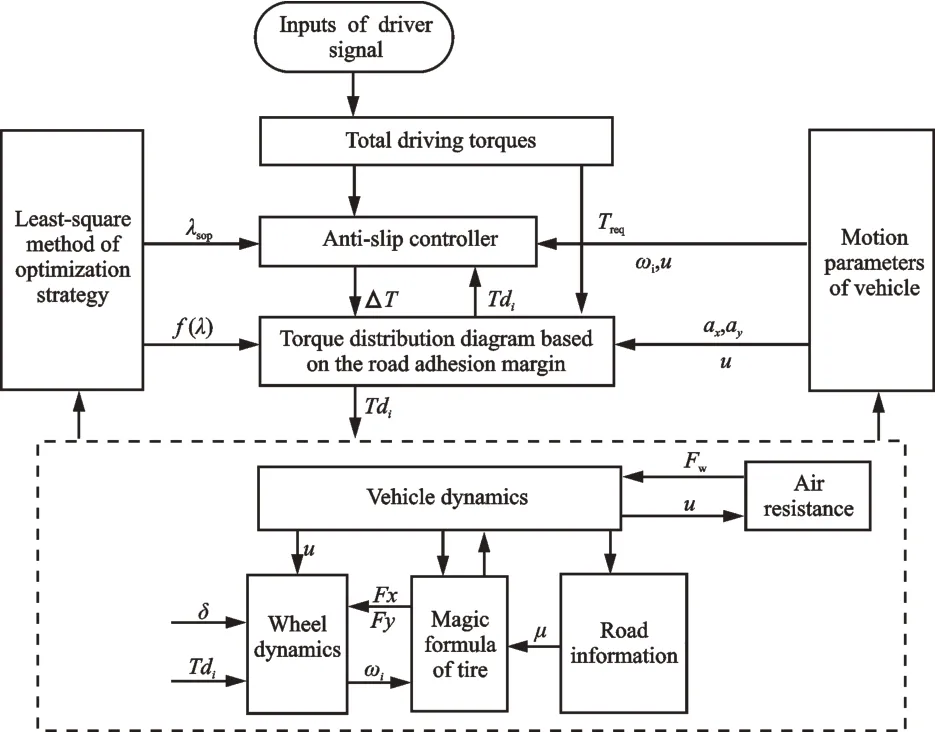
Fig.1 Torque distribution diagram
2.2 Anti-slip control
in this paper,the anti-slip control is designed based on the sliding mode - PiD control method,which can make the wheel provide the best driving force,and prevent it from slipping.
The relationship between the ideal and the actual wheel speed can be expressed as

where ωd(,)is the ideal wheel speed and λsopthe optimal slip ratio.
The error of the wheel speed is set as

Based on the sliding mode control theory,the switching surface Sωcan be written as

The sliding mode reaching law is designed based on PiD control method,which is set as[18]

where kp,kd,and kiare the proportion,differential and integral coefficients of the sliding mode reaching law,respectively.
Thus,the sliding mode control law Uwcan be expressed as

The integral saturation function sat is chosen as the switching function to make the variable reach the switching surface quickly,and reduce the jitter of the system effectively.

where εωis the setting boundary layer thickness of the sliding mode surface.
Therefore,it can be got as

where ΔTi(i=1,4) is the torque adjustment variable.
2.3 Torque distribution method
2.3.1 Road adhesion margin(RAM)
The road adhesion margin function is put forward based on the longitudinal and lateral adhesion capacity. Then,it is optimized with the least square method,to get the optimal slip ratio. Fig.2 shows the optimal slip ratio curve.

Fig. 2 Optimal slip ratio curve

The proposed road adhesion margin function can be expressed as where f (λ) is the road adhesion margin function,which is related to the slip ratio. μxis the longitudinal adhesion coefficient and μythe lateral adhesion coefficient.
Setting fmaxas the maximum of the road adhesion margin function,its residual error is defined as

where ε′is the residual error.
its variance is defined as

Differentiating the variance,then it should satisfy the following equation.

The slip ratio corresponding to this road adhesion margin function is the optimal one that considering the longitudinal and lateral adhesive ability.
2.3.2 Torque distribution
Assuming that the road conditions for the front and rear wheel are the same,their forces of Fz(f,)and Fz(r,)can be expressed as

where Fx(f,)and Fx(r,)are the driving forces of the front and rear wheel,respectively;Fy(f,)and Fy(r,)are the lateral forces of the front and rear wheel,respectively.
The load of the front and rear wheel can be got as

Synthesizing the above formulas,it can be got as

Considering the road adhesion margin,it can be derived as

Setting Cfrontas the distribution coefficient of the front and rear axle,it can be depicted as

where T1and T2are the distribution torques of the left and right front wheel,respectively;Treqis the expected torque of the driver.
Fig.3 shows the relation between the longitudinal acceleration and the distribution coefficient under different road adhesion coefficients. As can be seen from Fig.3 ,with the increase of road adhesion coefficient,the peak values of the distribution coefficient is decreased from 0.5 to less than 0.1,and the driving torque of the rear axle is slightly larger than that of the front one. Moreover,under the same road condition,the allocation of the driving torque is prior to the rear axle when the longitudinal acceleration is smaller.
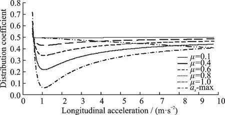
Fig. 3 Relation of distribution coefficient and longitudinal acceleration
3 Simulation Analysis
The simulation models are established with Matlab/Simulink software,and the simulation is carried out with high and low adhesion coefficient.Fig. 4 shows the torque distribution coefficient in high adhesion road(μ=0.8). it can be seen from Fig.4 that the distribution coefficient based on RAM distribution method is decreased quickly from the value of 1 to 0.5,then slowed down to about 0.4.The driving torques of the front and rear axle are distributed according to the ratio of 0.4,which can make full use of the road adhesion conditions. However,the distribution coefficients based on load ratio and average distribution method are all constant value regardless of the road conditions and the vehicle motion state.

Fig. 4 Torque distribution coefficient in high adhesion coefficient
Fig. 5 shows the simulation result of driving torque at high adhesion road(μ=0.8). it can be seen from Fig.5 that the driving torques of the front and rear axle based on RAM distribution method all tend to a stable value finally,and the front axle reaches the driving torque limit firstly. Because the distribution coefficient is less than 0.5,the driving torque of the front axle is smaller than that of the rear axle. However,the driving torques of the front and rear axle based on load ratio distribution method trend to a stable value in a short period of time,and the one based on average distribution method is a fixed value of 300 N.

Fig.5 Driving torque in high adhesion coefficient
Figs.6 and 7 show the simulation results of the slip ratio and longitudinal acceleration at high adhesion road(μ=0.8). it can be seen from the two figures that the slip ratio based on RAM distribution method can be effectively controlled in the range of 0.13 to 0.15,whose corresponding longitudinal acceleration can reach a large value. Moreover,the slip ratio based on load ratio distribution method can also be better controlled,but its control effect is less than the one based on RAM distribution method,and its corresponding longitudinal acceleration is only 2.2 m/s2. However,the simulation results of the slip ratio and longitudinal acceleration based on average distribution method are all not so good.
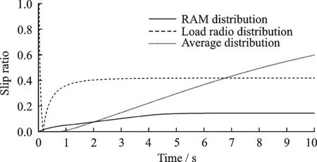
Fig.6 Slip ratio in high adhesion coefficient
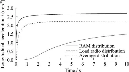
Fig.7 Longitudinal acceleration in high adhesion coefficient
Fig.8 shows the torque distribution coefficient at a low adhesion road(μ=0.2). it can be seen from Fig.8 that the distribution coefficient based on RAM distribution methods is reduced in a relatively short period of time. Eventually,the front and rear axles are distributed according to the value of 0.5.The distribution coefficients based on load ratio and average distribution method are a stable value of 0.58 and a fixed value of 0.5,respectively.

Fig. 8 Torque distribution coefficient in low adhesion coefficient
Fig.9 shows the simulation results of driving torque under three distribution methods(μ=0.2).it can be seen from Fig.9 that the driving torques of the front and rear axle based on RAM distribution method all tend to a stable value finally,and the one of the front axle is slightly less than the rear axle. in addition,the driving torques based on load ratio distribution method trend to a stable value in a short period of time,and the one of the rear axle is greater than the front axle,because of the longitudinal acceleration. However,the driving torque based on the average distribution method is a fixed value of 180 N.

Fig.9 Driving torque in low adhesion coefficient
Figs.10 and 11 show the simulation result of the slip ratio and longitudinal acceleration under three distribution methods(μ=0.2). it can be seen from the two figures that the slip ratio based on RAM distribution method is effectively controlled in a small range. and compared with the other two distribution methods,the corresponding longitudinal acceleration can achieve a larger value. Therefore,it can also get the excellent result with the RAM distribution method in low adhesion road.
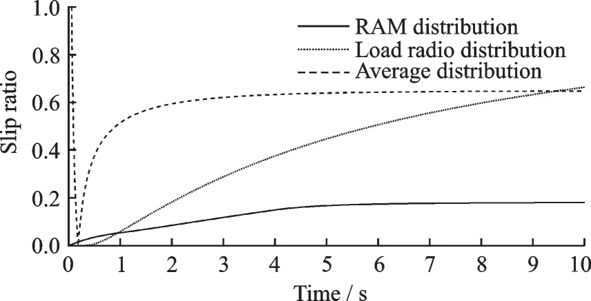
Fig.10 Slip ratio in low adhesion coefficient
4 Conclusions
in this paper,the tire model and the seven DOF dynamic model of the vehicle are established.

Fig. 11 Longitudinal acceleration in low adhesion coefficient
Then,by analyzing the influence of the longitudinal and lateral adhesion coefficient on the vehicle driving force,the torque distribution method is proposed based on road adhesion margin,which can be divided into the torque distribution layer and antislip control layer. The anti-slip control layer is built based on sliding mode variable structure control,whose main function is to avoid the excessive slip of the wheels caused by road conditions. The torque distribution layer is responsible for selecting the torque distribution method based on road adhesion margin. The simulation results show that the proposed torque distribution method can ensure the vehicle quickly adapt to the current road adhesion conditions,and improve the handling stability and dynamic performance of the vehicle in the driving process.
杂志排行
Transactions of Nanjing University of Aeronautics and Astronautics的其它文章
- Damage Detection and Material Property Reconstruction of Composite Laminates Using Laser Ultrasonic Technique
- An Efficient Method for Local Buckling Analysis of Stiffened Panels
- An Adaptive Transmission Scheme for Deep Space Communication
- High-Order Discontinuous Galerkin Method for Hovering Rotor Simulations Based on a Rotating Reference Frame
- Experiment on Boiling Heat Transfer of Refrigerant R134a in Mini-channels
- Self-Sensing Test Method for the Temperature of Piezoelectric Stacks
