Analysis of in-bore magnetic field in C-shaped armature railguns
2019-03-01QiangYinHeZhangHaojieLiYuxinYang
Qiang Yin,He Zhang,Hao-jie Li,Yu-xin Yang
Ministerial Key Laboratory of ZNDY,Nanjing University of Science and Technology,Nanjing,210094,China
Keywords:Railgun C-shaped armature Magnetic flux density
A B S T R A C T In order to analysis the distribution characteristics of in-bore magnetic field for C-shaped armature electromagnetic railgun,a computational model considering dynamic contact pressure is established.By solving the dynamic equation,the in-bore motion characteristics of the armature are obtained.The distribution of current in the rail and armature is analyzed based on the magnetic diffusion equation and Ampere's law.On this basis,three simulation models are proposed,which correspond to static state,motion state and motion state considering the velocity skin effect.The magnetic field of the investigated points along the central axes of the armature front end are obtained.The results show that,in static state,the peak magnetic flux density of each investigated point is greater than the other two states.Velocity skin effect leads to a decrease in peak magnetic flux density.The change of motion state has little influence on the peak magnetic flux density of the investigated point that far away from the armature.The calculated results can be used in the electromagnetic shielding design of intelligent ammunition.
1.Introduction
The electromagnetic railgun is a new concept weapon that uses electromagnetic force to launch projectile,it can be used to destroy space satellite of low earth orbit,to intercept invading missile[1][2].In order to achieve precise strike and expand the killing efficiency,the intelligent ammunition which contain control circuit is required to replace the conventional kinetic energy projectile[3].According to the principle of railgun,high current flows in the rails and armature will produce induced high magnetic field,it will make electromagnetic interference to the intelligent ammunition[4].Therefore,the in-bore magnetic field distribution characteristics must be analyzed before the design of magnetic shielding.
Cao[5]and Geng[6]analyzed the magnetic field in the vicinity of the rails,however,the investigated points are not located at the position of intelligent ammunition,meanwhile,the line current model they adoped may cause more errors.Li[7]established the three-dimensional analyticalcalculation model of in-bore magnetic field,but the effect of velocity skin effect on the current distribution of rails is not considered.Yin[8]analyzed the distribution characteristics of in-bore magnetic field and electric field,but the armature adopted is not C-shaped that commonly used in the launch test.
This paper establish computational model considering the contact characteristics between armature and rails.The in-bore motion characteristics of the armature are obtained by solving the dynamic equations.By solving the magnetic diffusion equation,the current distribution in the armature and rails is obtained.Finite element software is used to analyze the magnetic field ateach point of the intelligent ammunition position,the distribution characteristics of magnetic field at each investigated point is obtained.The results are helpful to the electromagnetic shielding design of railgun intelligent ammunition.
2.Calculation model and methods
2.1.Calculation model
There is an interference fit between the trailing arms of the armature and the rails to provide good solid-on-solid contact during the early portion of a railgun launch.Fig.1 shows the geometric structure schematic of conventional C-shaped armature for rectangular bore railgun,ltis the trailing arm length,dbis the bulk depth,r is the root-radius,Δd is the contact interference,dris the rear radial depth,s is the width of bore,s1is the width of the front end of the armature.

Fig.1.Structural parameters of a C-shaped armature.
Fig.2(a)shows the 2D model of railgun,the current in flow from one side of the rail, flow through the armature,and out flow from the other side of the rail,the armature moves under the action of electromagnetic propelling force.We set the center of curvature circle as the origin of the coordinates,set the armature axis as the x axis,the direction of rail to rail as the y axis,the direction of armature height as the z axis.θis the angle of trailing arm,P is the investigated point.Fig.2(b)shows the side view of the railgun,w is the width of the rail,haand hrare the height of the armature and rail.
2.2.Calculation methods
In this paper,we ignore the nonlinear effects of rail erosion caused by high speed movement between armature and rails.Because the size of the launching system of railgun is far less than the wavelength of electromagnetic field,the displacement current can be ignored.We study the railgun as a quasi-static system.The differential form of the Maxwell equation is as follows:

Combined with Ohm's law,J= σ(E+v×B),the B= μH,the equation can be written

In the 2D computational model of railgun,we can use the Bzto replace the H,the magnetic diffusion equation can be written as

By setting the boundary conditions of the system and the initial value of Bz,solving equation(5),we can get the Bzin the armature and rail.The current density in the rail and armature can be obtained by using Ampere's law.

Using Biot Savart law,the magnetic flux density of the investigated point can be obtained.

The calculation flow chart is shown in Fig.3,through the analysis of the initial contact state,the armature mechanical preload force is obtained.By solving the dynamic equations,we can get the in-bore motion characteristics of the armature.The current distribution in the armature and rails can be obtained by solving the magnetic diffusion equation and by using Ampere's law.Considering the current distribution characteristics under different conditions,three FEM simulation models are established to analysis the in-bore magnetic field.
3.In-bore dynamic analysis of armature
In the process of in-bore movement,the armature affected by the electromagnetic propelling force,the atmosphere drag,the solid-solid friction force.The resultant force will determine the speed and displacement of armature.For atmosphere drag,the study shows that it has little in fluence on the in-bore dynamic characteristics of armature[9].This paper mainly studies the friction force between armature and rail.
The friction force can be written as

Whereμis a friction coefficient,it can be expressed asμsfor static friction coefficient andμkfor kinetic friction coefficient.FNis the contact force between armature and rails,The contact pressure mainly consists of two parts:the mechanical preload force FNMand the electromagnetic load on the armature's trailing arm FNEM.In the initial state,the contact pressure is the mechanical preload force,the electromagnetic force increases with the input of the current.In static condition,because the current is small,the mechanical preload force is larger than the electromagnetic force.When the armature is in motion state,the electromagnetic force plays a dominant role in the contact pressure[10].The resultant force can be expressed as

Fig.2.The 2D computational model of railgun.

Fig.3.Calculation flow chart.

Fpis the electromagnetic propelling force.
The velocity of the armature can be written as

The displacement of the armature can be written as

m is the mass of the armature,x0is the initial displacement value of the armature.
3.1.The contact force between armature and rail under static state
As shown in Figs.1 and 2,the trailing arm length of the armature is 35 mm,dris 2 mm,Δd is 1 mm,r is 5 mm,s1is 16 mm.The width of the bore is 30 mm,the height of the armature is hais 30 mm,the height of the rail is 40 mm,the width of the rail is 20 mm.The armature material is Al-6063 alloy,the rail material is copper alloy.
Using the simulation method in Ref.[11],we can get the contact pressure distribution at the armature surface after assembly.As shown is Fig.4,the maximum contact pressure point is located at the central edge of the armature tailing arm.By integrating the contact pressure of the contact surface,the initial mechanical preload force FNMis obtained,it is about 16.5 kN.
Fig.5 shows the contact pressure distribution at the armaturerail interface after assembly,the distribution of the contact pressure ranges from 7 to 22.8 mm,the maximum contact pressure point is located at 19.6 mm.

Fig.4.Contact pressure distribution at the armature surface after assembly.

Fig.5.Contact pressure distribution curve at the armature-rail interface.
Research shows that the contact pressure and contact position of armature and rail will directly affect the way the current enters the armature.When the armature is in a static state,the current flow into armature mainly from the maximum contact pressure point,when the armature in a motion state,the current flow into armature from the rail at the armature trailing edge[12][13].In Fig.2,the lcis the diatance from the maximum pressure point to the leading edge,αis the angle between the current path and the x axis.It is assumed that the magnetic flux density B is uniform around the armature trailing arm.The electromagnetic propelling force[13].

L’is the inductance gradient,electromagnetic force perpendicular to the armature trailing arm

The magnetic pressure at the armature-rail interface

During the moving process of the armature,the current enters the armature from the trailing edge,then the lcis equal to lt.
3.2.Dynamic analysis of armature
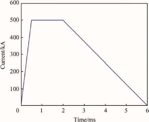
The armature are all pulsed with 500 kA of current from 0.5 to 2 ms and then brought down to 0 A by 4 ms,as indicated in Fig.6.
L′is 0.42μH/m according to Kerrisk's calculation equation in Ref.[1].The mass of the armature is 65 g,the static friction coefficientμsis 0.3,the kinetic friction coefficientμkis 0.1[9],the length of the railgun is 2 m,the initial displacement is 0.15 m.

Fig.6.Waveform of driving current.

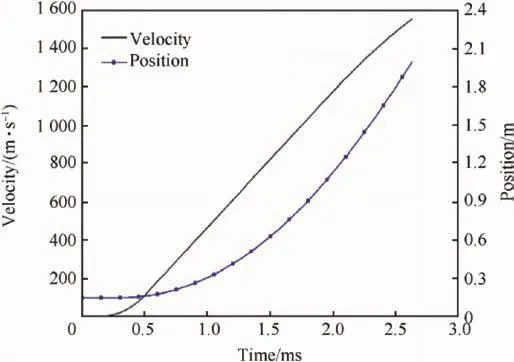
Fig.7.Motion curves of armature.
Using the current value in Fig.6,from Equations(8)-(11)and(14),the dynamic characteristics of the armature can be calculated.As shown in Fig.7,the muzzle time is 2.6 ms and the muzzle speed of the armature is 1557 m/s.
4.Simulation of the in-bore magnetic field
4.1.Analysis of the current density distribution
The electrical conductivity of the rail is 5.8×10⁷S/m,and the conductivity of the armature is 3.1×10⁷S/m.According to material parameters and armature motion characteristics,using the PDE module in the finite element software COMSOL Multiphysics 4.4 to solve Equations(5)and(6),The current distribution of armature and rail at different times can be obtained,the specific boundary conditions can be set up according to[8].

Fig.8.Streamline plots of current density at 0.45 ms,1.4 ms,1.9 ms.
Fig.8 shows the current streamline plot at 0.45 ms,1.4 ms and 1.9 ms.It can be seen from the graph that the current distributes along the back end of the rail due to the velocity skin effect,The greater the armature speed,the smaller the skin depth.The current flows into the armature and diffuses from the narrow area where the armature tailing arm is in contact with the rail.By comparing the current density distribution at each time in Fig.8,it is found that the velocity skin effect has great in fluence on the current distribution in the rail,but it has little effect on the current distribution of the armature.Due to magnetic diffusion,the internal current of the armature gradually extends from the throat to the front end.
In Ref.[14],the contact current penetration lengthδvaccording to the theory of velocity skin effect can approximate given by

whereμ0is magnetic permeability,the resistivity of Al-6063 alloy armature ρais 32 nΩm,the resistivity of copper railρris 17 nΩm,v is the speed of armature,θ is the angle of trailing arm,θ=12°.The average speed is 800 m/s when the time is 1-2 ms,it can be obtained thatδv=1.5 mm.
4.2.Simulation models
At present,most commercial finite element software can not carry out the electromagnetic simulation for the motion system.In order to obtain the magnetic field variation rules at different investigated points,Three models to simulate the in-bore magnetic field under different conditions were established.

Fig.9.Schematic diagram of 1/2 simulation model 1.

Fig.10.Schematic diagram of 1/2 simulation model 2.
Model 1:When the armature is in static state,the current flow into armature mainly from the maximum contact pressure point.It can be seen from Fig.5 that the maximum pressure point is located at 19.6 mm,the pressure is 158 MPa,the contact pressure is 154 MPa at the 20 mm point,the two are relatively close,so we set up the contact length between the rails and armature trailing arm is 20 mm.This model is mainly used to simulate the static state,as shown in Fig.9.
Model 2:When the armature is in motion state,the current flow into armature mainly from the rail at the armature trailing edge.The contact current penetration lengthδvcan be calculated according to[15],We ensure the penetration length of the current by setting the contact length between the armature and rail.As armature continues to accelerate under the action of electromagnetic propelling force,in order to set contact length conveniently,the average speed at 1-2 ms is used to calculate,the average speed is 800 m/s,it can be obtained that the contact length is 1.5 mm.As shown in Fig.10,the model is established to simulate the motion state.
Model 3:The model 2 mentioned above does not consider velocity skin effect.In fact,under the velocity skin effect,the current flows mainly along the inner surface of the rail.It can be seen from Fig.8 that,the greater the armature speed,the smaller the skin depth.For the rail behind the armature,the closer to the armature,the smaller the skin depth is,the skin depth increases with the increase of the distance from the armature,but it is far less than the width of the rail.The model is bulit by reducing the width of the rail,as shown in Fig.11,the width of the rail at the initiating terminal is 4 mm,it is gradually reduced to1mm at the end,The size of this shape mainly refers to the current density in Fig.8(b).The difference between this model and model 2 lies mainly in the shape of the rail,this model is mainly used to simulate the motion state considering the velocity skin effect.
The size of the armature in the three models is consistent.The length of the rail is 150 mm(in order to meet the four caliber rule).
4.3.Analysis of the simulation results
In the computational model of railgun as shown in Fig.2,take into account the actual location of the intelligent ammunition,we take six points ahead of the armature to investigate,they are on the x axis,their coordinates are(25 mm,0,0),(35 mm,0,0),(45 mm,0,0),(55 mm,0,0),(65 mm,0,0),(75 mm,0,0).It is easy to see that,only+z direction magnetic flux density exists in the investigation point.The current flowing through the armature which along the y axis generates magnetic flux density of+z direction,the current flowing through the rails which along the x axis generates magnetic flux density of-z direction.

Fig.11.Schematic diagram of 1/2 simulation model 3.

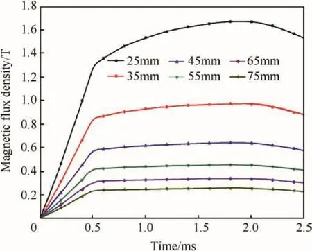
Fig.12.The magnetic flux density value of each investigated point.

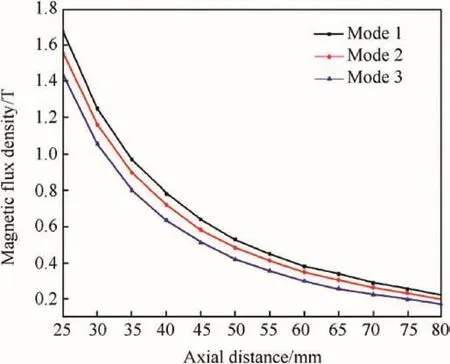
Fig.13.The peak magnetic flux density value of each investigated point.
We use the magnetic field module in the finite element software COMSOL Multiphysics 4.4 to analysis the magnetic flux density of the points,the model 1 mentioned above is used.The results are shown in Fig.12.
When the time is 0.5-2 ms,the driving current is 500 kA,to the point(25 mm,0,0)and(35 mm,0,0),the value of magnetic flux density shows a certain tendency to increase,it is mainly due to the current diffusion inside the armature.For other points,the effect of current diffusion on them is relatively small.
The in-bore magnetic field distribution under different state was investigated,The inspection point is located on the x axis,and the abscissa is from 25 mm to 80 mm.Using the three models mentioned above to analyze.The results are shown in Fig.13.
It can be seen from Fig.13 that the peak magnetic flux densities of each investigated point decrease gradually with the increase in the distance from point to armature.For the same point of view,the peak magnetic flux density of the first model is the largest,and the peak magnetic flux density obtained by the third model is the smallest.Thus,it can be seen that when the armature is in a state ofrest(corresponding to model 1),the current enter the armature at the middle of the armature trailing arm,and the peak flux density is greater than thatof the motion state.This is mainly due to the y axis component flowing through the armature current is larger than the other two models.When the current is concentrated on the surface of the rail(corresponding to model 3),the-z direction magnetic field generated by the x direction current flowing through the rail will increase,which will lead to the decrease of the peak magnetic flux density.

Table 1 The peak magnetic flux density value of each investigated point under the condition of different l h.

Table 2 The peak magnetic flux density value of each investigated point under the condition of different l t.
4.4.Discussion
The effect of C-shaped armature size changes on peak magnetic flux density is discussed below.Four points can be took,P1(25 mm,0,0),P2(35 mm,0,0),P3(45 mm,0,0),P4(55 mm,0,0),using the model 3 to analysis.The in fluence of armature parameter adjustment on armature dynamic characteristics can be ignored.
First,the length of the armature front end was adjusted.The results are shown in Table 1.It can be seen that with the decrease of the length of the armature front end,the peak magnetic flux density decreases gradually,which reflects the effect of the current diffusion on the magnetic flux density(as mentioned above).
Next,the length of the armature tailing arm was adjusted.The results are shown in Table 2.It can be seen that with the increase of the length of the armature trailing arm,the peak magnetic flux density decreases gradually.
It can be seen from Tables 1 and 2 that small adjustments in armature size can have a certain effect on the peak magnetic flux density to the point that near the armature.But for the points far away from the armature,they are mainly affected by the space attenuation effect.
5.Conclusions
In this paper,aimed at the C-shaped armature railgun,three different simulation models are established to analysis the in-bore magnetic field,which correspond to three different armature states,namely,static state,motion state,motion state considering velocity skin effect,the in fluence of armature size on the in-bore magnetic field is also analyzed.The following conclusions can be obtained:
(1)At the static state,the peak magnetic flux density of each investigated point is larger than that in the moving state.
(2)Compared with the other two states,the peak magnetic flux density of each investigated point decreases with the moving state considering the velocity skin effect.
(3)When the current amplitude,the width and height of the rail and armature are fixed,the size of the armature can be adjusted by a small amplitude,which has a certain degree of in fluence on the peak magnetic flux density to the point near the armature.
(4)For the investigated point far away from the armature,the change of the armature motion states has little effect on their peak flux density,and they are mainly in fluenced by the effect of space attenuation.
Acknowledgment
This work is supported by the Key Basic Research Projects of Basic Strengthening Plan under Grants 2017-JCJQ-ZD-004.
杂志排行
Defence Technology的其它文章
- Fluorine-containing oxidizers for metal fuels in energetic formulations
- On the formation of Basu's Type III(peeled orange)gunshot residues
- Interaction of TATB with Cu and Cu+1.A DFT study
- Control of exterior ballistic properties of spin-stabilized bullet by optimizing internal mass distribution
- Crystal lattice free volume and thermal decomposition of nitramines
- Tribological and vibrational characteristics of AISI 316L tested at elevated temperature and 600 Torr vacuum
