Fluorine-containing oxidizers for metal fuels in energetic formulations
2019-03-01SivKumrVlluriMirkoSchoenitzEdwrdDreizin
Siv Kumr Vlluri,Mirko Schoenitz ,Edwrd Dreizin ,b,*
a New Jersey Institute of Technology,Newark,NJ,USA
b Tomsk State University,Tomsk,Russia
Keywords:Reactive materials Composites Redox reactions Pyrotechnics Propellants Explosives
A B S T R A C T Fluorine containing oxidizers,primarily polymers,are extensively used in pyrotechnic compositions.Fluorinated oxidizers are less explored for metalized propellants and explosives despite a potential advantage of substantial heat release combined with gaseous combustion products.This review summarizes different types of fluorinated oxidizers used in energetic formulations or of potential interest for such systems,including gases,polymers,and inorganic compounds.Types of energetic formulations employing metals and fluoropolymers are discussed in more detail,including methods used to prepare composites and resulting salient features of the obtained materials.Laboratory experiments characterizing such materials,in particular,electron microscopy and thermal analysis,are discussed,showing characteristic morphologies and reaction sequences observed in different metal- fluorinated oxidizer composites.Striking similarities are noted in reaction sequences for diverse compositions hinting at possible similarities in the respective reaction mechanisms.Experiments probing ignition and combustion of metal- fluorinated oxidizer composites in laboratory conditions are also reviewed,including impact, flash heating and shock ignition.Finally,some practical performance tests for energetic formulations are described following by a brief discussion of the reaction mechanisms expected to govern ignition and combustion in various metal- fluorinated oxidizer composites.The conclusions are combined with recommendation for future research in the area of reactive metal- fluorinated oxidizer composites.
1.Introduction
Metal powders may serve as excellent fuels due to their high volumetric and gravimetric heat release upon combustion[1-7].They also generate high combustion temperatures,sometime in excess of 3000 K,attractive for high-efficiency propellants,enhanced blast explosives,and specialized pyrotechnics[4-7].Applications in dual use materials,such as structural energetic or reactive materials are also explored[8-10].The thermodynamic benefits of metals,however,are often offset by their relatively long ignition delays,low burn rates,and generation of condensed products,such as oxides,as a result of combustion[11].Condensed oxides reduce work produced by the burning energetic composition and cause so-called two-phase losses[12-14],which are detrimental for solid propellants and some explosives.In many energetic formulations,metals are combined with aggressive oxidizers,such as sodium or potassium perchlorate[15,16],to increase their reaction rate.However,use of such aggressive oxidizers is associated with difficulties in handling and storing energetics.In addition,it is important to reduce environmentally undesirable emissions,e.g.,corrosive chlorinated products.In some cases,metals may be combined with other oxidizing compounds,such as metal oxides in thermite compositions[17-20].Such compositions are capable of generating very high temperatures,however,the shortcomings associated with the low burn rates and final condensed products remain.An approach of increasing the burn rates for metals by reducing the sizes of metal particles and mixing them with finely divided oxidizers has been actively explored over the last decade[7].Indeed,the ignition delays were observed to shorten;however,the burn rates commonly are weakly affected because of rapid sintering of nanostructured materials,which thus lose their structural advantages upon ignition[21,22].Furthermore,the sensitivity of the nano-scale metal-oxidizer systems to various ignition stimuli,including,in particular,electrostatic discharge(ESD),was also reported to become very high[23],making it difficult to handle such materials.In summary,ignition delays,low burn rates,high sensitivity to ignition by ESD,and generation of condensed oxides as combustion products are main impediments to wider use of metal fuels in advanced energetic formulations.Fluorinated oxidizers may alleviate some of the above issues,mostly due to the combination of high heats of formation of metal fluorides,comparable to that of metal oxides,with the relatively high vapor pressure of metal fluorides and oxy fluorides,which volatilize more readily than refractory oxides for most of the energetically interesting metals.
Fluorine is the most electronegative element known,with the electronegativity of 3.98 on Pauling scale[24].It is more reactive than most non-metals,and is therefore not found in nature in its elemental form.Its unique behavioral traits arise from multiple factors such as relatively small atomic size,strong electron affinity,weak molecular F-F bond,and weak polarizability.These characteristics can be combined in the concept of chemical hardness[25].Calculated atomic radii and reported values of the chemical hardness are shown in Table 1.Indeed, fluorine is the hardest Lewis base of the typical oxidizing elements.The oxidation strength of fluorine-based species compared to other halogens in aqueous solutions is greater or,in some cases,comparable to chlorine[26].
The product of fluorination,the reaction wherefluorine oxidizes a metal/metalloid and sometimes non-metals like oxygen,hydrogen and even inert gases like xenon,is primarily a fluoride.The enthalpy of formation of some fluorides and their corresponding oxides of some reactive metals are compared to each other in Fig.1.The values are shown normalized by the number of metal ions(a)and by number of anions(b),respectively.Per mole of fuel consumed,formation enthalpies of metal fluorides always considerably exceed those of their respective oxides.However,due to the valence difference between fluorine(1)and oxygen(2),formation enthalpies per fluorine anion are on average about 50 kJ/mol less exothermic than per oxygen anion.Thus,deciding whether use of fluorine as oxidizer is thermodynamically advantageousdepends on whether an application is limited by the amount of fuel or oxidizer.Further,the enthalpies of formation of binary fluorides exceed those of other halides for carbon[28,29],boron[30],all alkali metals[30],and even phosphorus(III)[30].
Table 1 Calculated atomic radii[27],and chemical hardness values[25]of some common oxidizing elements.
In addition to thermodynamic considerations,formation rates are systematically different between fluorides and oxides.The rates of scaling metals by both fluorine and oxygen are limited by diffusion of the reactants through a growing layer of product forming at the fuel/oxidizer interface[31].For example,it has been reported that the scaling of iron by fluorine gas has a low activation energy of 8.4 kJ/mol in the temperature range of 225-525°C[31].On the other hand,oxidation of iron in oxygen below 570°C is reported to have a much higher activation energy ranging from 130 to 160 kJ/mol,depending on the crystal orientation[32].The heterogeneous oxidation of iron remains slow even at much higher temperatures exceeding 900°C[33].
For practical purposes, fluorine as an oxidizer is available from gaseous,polymeric and inorganic compounds.The dissociation energies of selected bonds in such compounds are presented in Table 2.Bond dissociation energies are expected to be a factor,in fluencing ignition in energetic composites.The bond dissociation energy of solid metal fluorides is slightly higher than the dissociation energies seen in fluorine-based gases like F2and SF6,and comparable to that of C-C bonds in fluorocarbons.Compared to inorganic gases,the C-F bonds in fluorocarbons are more stable by about 100 kJ/mol,making the energetic cost of fluorine release slightly higher[32].
The bond energies given in Table 2 for metal fluorides and SF6are average values.Typically, fluorine atoms are dissociated one at a time,and the bond energies for the first and subsequent fluorine atoms removed from a fluoride are different.The bond energy of the first removed fluorine is likely to be the greatest,making it easier to cleave subsequently dissociated atoms.Thus,the values in Table 2 may serve only as a first approximation when assessing prospective ease of metal ignition using a metal fluoride as compared to fluorinated polymers as oxidizers.Note also that the bond energies in fluorocarbon polymers may be higher than shown in Table 2 due to the contribution of the other per fluorinated groups and chains attached to the carbon in question.However,in all fluorocarbons,the C-C bonds are comparatively easier to cleave compared to the C-F bonds,and therefore carbon-carbon dissociation often precedes release of fluorine during decomposition of carbon-based fluoropolymers.
Fig.1.Enthalpies of formation of selected fluorides and corresponding oxides of reactive metals.

Table 2 Bond energies of gas phase oxidizers,common fluorocarbon bonds and fluoride bonds of some prospective metal fluoride oxidizers.
Potential advantages of fluorinated oxidizers with metal fuels may also be associated with the type of formed combustion products.The properties of metal fluorides formed as combustion products are quite different from their corresponding metal oxides.Table 3 contains relevant thermochemical and physical properties of some of the fluorides and oxides of metals used or considered for use in energetic formulations.The fluorides are usually more volatile than the corresponding oxides,and in some cases,the fluorides are gases at standard conditions.These cases includefluorides of practically important fuels boron and silicon:boron fluoride(BF3)and silicon tetra fluoride(SiF4).The semiconductor industry exploits this by using fluorine-rich gases,like SF6,to etch silicon wafers removing the gaseous product SiF4[38].Another important combustion product of aluminum,aluminum fluoride(AlF3)sublimates readily[39]unlike the refractory Al2O3.In presence of oxygen,the oxy- fluorides(e.g.,of boron and aluminum)may be formed,which are usually gaseous species as well.Thus,adding fluorine as an oxidizer for metal combustion makes it possible to generate more gaseous products and thus avoid or minimize the two-phase losses caused by the formation of condensed metal oxides[40,41].At the same time,the effect on the energy released or flame temperature is relatively minor.For example,effects of using a fluorinated additive,polytetra fluoroethylene(PTFE or Te flon®),to an aluminized solid propellant with ammonium perchlorate(AP)as the main oxidizer and hydroxyl-terminated polybutadiene(HTBP)as a binder were considered in Ref.[42].Calculated effect of pressure on the flame temperature for such a propellant is shown in Fig.2.Sublimation temperatures for AlF3are shown for comparison.Adding PTFE reduces the adiabatic flame temperature slightly,however,the temperature remains much higher than the temperature of sublimation of AlF3for the entire range of pressures considered.Thus,gas products are generated,whereas without PTFE,most of the products predicted to form in equilibrium are condensed oxides.Note that the AlF3sublimation temperatures are not attained for the 90%Al composition without the AP,while they are achieved if 70%Al react with 30%PTFE.Combining the AP with PTFE makes it relatively easy to custom tailor the flame temperature and reaction product makeup.

Table 3 Physical and thermochemical properties[43]of metal fluorides and their oxide analogs.
Fig.2.Different formulation flame temperatures and aluminum fluoride sublimation[42].
1.1.Types of fluorinated oxidizers
1.1.1.Gases
The use of elemental fluorine,as an oxidizer has long been considered in aerospace and aeronautic propulsion systems.Fluorine-liquid oxygen or FLOX,has been explored as an oxidizer in hybrid propellant engines for lithium based fuels[44].It was also suggested to use FLOX with aluminized fuels in hybrid engines[45].However,because of concerns over safety and handling procedures for extremely potent oxidizing agents like OF2and other active species,the studies on FLOX application were rather limited.
Fluorine based gases,which are relatively stable and even inert in most conditions,like SF6,have been used as oxidizers for metallic fuels in laboratory experiments.Aluminum was found to burn in SF6environment without any condensed phase products[46].In the same study,it was shown that for a broad range of ratios of oxygen to fluorine(present as SF6),formation of oxy- fluorides,like AlF2O,effectively reduces the formation of condensed Al2O3.Despite being non-toxic and easy to handle,SF6is not a practical oxidizer.It is not attractive thermodynamically because of its relatively high heat of formation.The presence of sulfur is also undesirable for most metal-based energetic systems.
Generally,gas oxidizers are less attractive for energetic formulations than condensed phases,capable of high packing densities,and,respectively,high energy densities.
1.1.2.Fluorocarbons
The discovery of polymers offered a stable,diverse,and safe group of fluorinated condensed phases,which could be incorporated into energetic formulations relatively readily.Although the mechanical properties of polymers were initially found to be conducive to use as binders,their utility as oxidizers was also appreciated early on.Table 4 has a list of commonly used fluoropolymers.Very few polymers in this list are per fluoropolymers,i.e.,composed only of carbon and fluorine.The rest contain hydrogen or other halogens,like chlorine.The per fluoropolymers are of particular interest as they have greater fluorine content.Among different fluoropolymers,PTFE finds the widest range of applications in energetics.Table 5 lists some of the per fluorinated carboxylic acids used in energetics.These acids are large,linear molecules,which are completely fluorinated,save for the carboxylic groups at the chain ends.
In Fig.3,the decomposition temperatures and fluorine content for materials introduced in Tables 4 and 5 are shown.The polymers are grouped into three quadrants;each quadrant could be associated with common applications.Polymers in quadrant(A)have higher carbon/low fluorine content combined with higher decomposition temperatures.As oxidizers,they typically react relatively slowly yielding carbonaceous products.This makes such polymers useful forapplications in pyrotechnic formulations including various visible light and infrared obscurants and screens.Obscurants have been prepared with PCTFE[47],PVDF[48],and PMF[49].Fluorocarbons in quadrant(C)have been used to coat reactive metallic powders to protect pyrophoric compositions[50]and to modify their combustion behavior[51,52].They have been used as‘surface enhancers’due to high fluorine content and thus enhanced reactivity and hydrophobic properties;they are stable at room temperature but deteriorate as temperature rises [50,53].These are primarily per fluorinated alkylcarboxylic acids.The polymers shown in quadrant(B)are most interesting for broader ranges of applications in energetics.They have both,high decomposition temperature and fluorine content.Due to higher fluorine content,reactivity is improved and gaseous products are readily produced.At the same time,the polymer oxidizers are robust,enabling longer storage and allowing for processing at elevated temperatures.In general,simple polymers in quadrant(B)may be tailored to perform as pyrolants[54],propellants[55]and explosives[56].
The fluorocarbons used thus far are conventional linear polymers/acids exploiting the exothermicity of the energy stored in C-F bonds.An extension of the energetic benefits,through strained structures was suggested by Koch[57].Based on their enthalpy of combustion,as a measure of strained carbon skeletons and their hybridization and fractional electron transfer,as a measure of reactivity,several compounds were considered of interest.The reactivity is ranked highest for the most strained structures, fluorofulleranes.These fluorocarbons are prospective oxidizers that require further experimental focus.
1.1.3.Metal fluorides
Metal fluorides may be useful as stable solid fluorinated oxidizers although we were unable to find references to respective experimental or practical formulations aside from some very recent work[58,59].The crystalline nature of these salts makes them stronger and more brittle compared to soft polymers.Thus,mixing metal fluorides and metals may be achieved more readily by mechanical milling,used recently for preparation of many metalbased reactive materials with attractive properties[59].The properties of metal fluorides vary widely;some of the more stable and less hygroscopic materials,such as CuF2,CoF2,BiF3and NiF2,may be more attractive as oxidizers than other fluorides,which are difficult to handle at ambient humidity.
Enthalpies of formation,normalized by mole of fluorine,for some potential metal fluoride oxidizers are shown in Fig.4 along with that for PTFE.All metal fluorides carry a thermodynamic penalty as oxidizers,compared to PTFE.However,and as discussed above and shown in Table 3,the combustion products in thermite reactions with commonly used fuels,e.g.,Al or B arefluorides and oxy- fluorides that are more volatile than oxides.This allows for large volume of gaseous products,comparable to that produced by the compositions with polymeric oxidizers.In addition,metal fluorides may be processed by powder methods,and the absence of carbon may account for different initiation reactions,and associated kinetics.Both issues will be discussed further below.
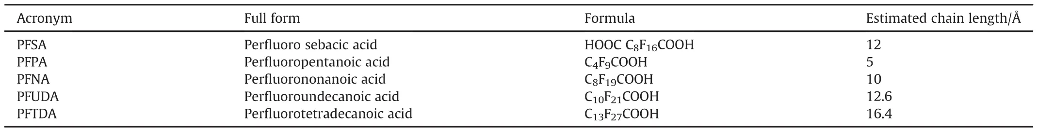
Table 5 Per fluorinated alkylcarboxylic acids used in energetic compositions.
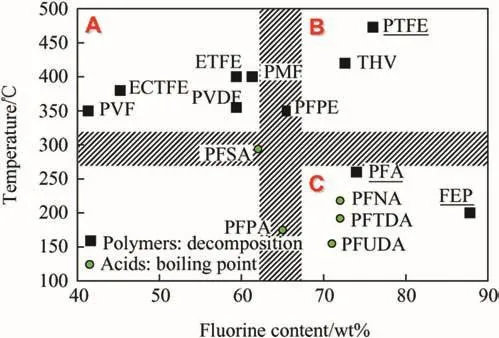
Fig.3.Fluorinated polymers and acids based on their fluorine content and decomposition temperatures or boiling points.
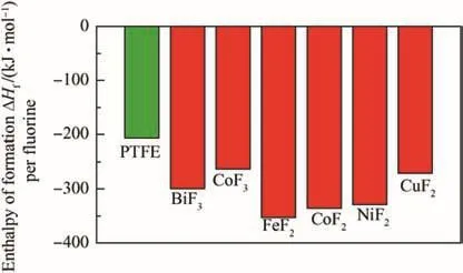
Fig.4.Heats of formation of PTFE[60]and prospective metal fluoride oxidizers(from Ref.[43]).
1.2.Metal-based energetic systems with fluorine-containing oxidizers
1.2.1.Pyrotechnics
Pyrotechnic compositions are developed as igniters and initiators,including delay lines;they are also designed to generate specific gases,pressure profiles,high temperature,light,and sound effects.Energy density may be a less important metric for pyrotechnic formulations customized to generate optical emission with specific spectral range and duration,and achieve precise timing of the combustion event.Fluorinated compounds are used most extensively in this class of energetics.For example,magnesium-Te flon®-Viton(MTV)is a very common composition for various pyrotechnic formulations[61-63]as elaborately summarized by Koch in Ref.[64].Metal- fluoropolymers constitute a very important type of pyrolants as reviewed in Ref.[65].The majority of the compositions and materials contain PTFE polymer as the primary source of fluorine species.Table 6 provides a few examples of fluoropolymer based compositions used in pyrotechnics.
While metal- fluoropolymer compositions are used in practical pyrotechnics,current work remains active aimed at improving mixing and morphology of metal- fluoropolymer composites,characterizing their aging,as well as extending the range of time delays,temperatures,emission and pressure patterns achievable with such materials.
1.3.Propellants
Unlike pyrotechnics,most metalized propellant and explosive compositions including fluoropolymers remain experimental.For both propellants and explosives,energy density is of primary importance and thus additives,which might reduce the energy density,even if improving reaction rate and gas generation,may be unacceptable.For example,Mg/PTFE propellants have attractive burn rates,but their energy density is relatively low.Efforts are currently active to increase their energetic potential by adding boron-based thermites[77].
Materials for consideration as explosives and propellants include milled materials[78-81]and consolidated mixtures[82].The constituent fuel powders are often micron sized spherical aluminum[56,78-82]and magnesium[79].Additionally,nano-metric aluminum(n-Al)powder has also found use in underwater explosive formulations[83,84].The oxidizer of choice for such propellant/explosive systems has been micron sized Te flon®[56,78,80-82,85].

Table 6 Examples of fluoropolymers used in pyrotechnic formulations.
The milled materials have all been prepared using interrupted milling runs,to allow for intermittent cooling of the milled powders.Various compositions were tested;compositions with close to stoichiometric Al/PTFE ratio,approximately 30 wt%of Al,were found to have the highest flame velocities[85].However,for propellants,very fuel-rich compositions with ca.70 wt%of Al were favored[80,81]as the objective was to maximize the aluminum content enabling reaction with other oxidizers.Primary oxidizers,such as AP were added to employ PTFE as a secondary oxidizer/gas generator reacting with the aluminized fuel[80].With added PTFE reduced agglomeration of condensed combustion products of an aluminized solid propellant was observed in Ref.[80].This is illustrated in Fig.5.Reference propellants used spherical Al, flake Al,and n-Al powders.For spherical Al,most of the particles become bright,and thus ignite,at a significant distance from the propellant surface.For flake Al,ignition appears to be closer to the propellant;however,most burning streaks are produced by very large,slowly burning droplets.In both cases,the thermal feedback from metal combustion to the propellant is negatively affected by the slow heat release at a distance from the propellant surface.Particles of n-Al ignite close to the propellant surface;however,the heat release is negatively affected by their relatively lower energy content,diminished because the surface oxide layer comprises a substantial volume fraction of the material[86].With PTFE added,micronsized aluminum particles are less agglomerated;they ignite and burn close to the propellant surface.This is expected to lead to an improved performance of the solid propellant.Several recent efforts considered solid propellants combining mechanically activated(ball milled)aluminum with PTFE[87,88],observing an increased burn rate without decrease in the propellant's energy density.
Boron is pursued as a replacement to aluminum in metal/ fluoropolymer propellant compositions due to its high volumetric and gravimetric energy density.Primarily,PTFE was used as the polymer in almost all of these preparations.It was found by Young et al.[89],that the ignition and combustion behavior of boron was improved by addition of PTFE in experiments with heating rate of 105K/s and various pressures to simulate propellant burning conditions.In a lab scale propellant experiment,linear regression rates of sintered and un-sintered powders in a diffusion flame were measured with gaseous oxygen as an added oxidizer.Sintered mixtures of B/PTFE,containing mass percentages greater than 25 wt%of boron were found to not combust at atmospheric pressures in the absence of pure oxygen.Forun-sintered mixtures at the same condition,boron mass percentage could reach up to 30 wt%for combustion to occur[90].The formation of gaseous BF3and hydrolyzed B(OH)3was confirmed through FTIR.At elevated pressures,the fuels tested could self-propagate without additional oxygen with up to 40 wt%boron loading due to improved porosity[91].Several practical propellant experiments in hybrid rocket engines[92]and small-scale ramjet engines[93]were undertaken to test the B/PTFE fuel in solid propellants.
Boron has also been explored as an additive to fluorinated propellant formulations with another metal as a primary fuel.Studies with boron added to Mg/PTFE propellant compositions show the propellant ignited less readily though its overall combustion heat was improved[94].A different study used pressed pellets of sonicated blends of milled Si and PTFE powders,in which silicon was doped with different amounts of boron.The apparent activation energy of the reaction decreased while the burn rates of the pellets increased with increase in the doped boron content[95].
1.3.1.Explosives
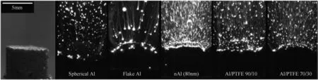
Fig.5.Images solid propellant combustion with different aluminum-based additives,including PTFE[80].
The PTFE-containing systems explored for potential use in explosives did not have any added oxidizers apart from PTFE but contained initiators like RDX and HMX representing less than 15 wt%of system[56,79,82].The use of metal- fluoropolymer composites in explosives was also discussed in Refs.[96,97],where it was suggested that Al-PTFE mixtures subjected to high energy ball milling,consolidated,and initiated with a primer are capable of detonation.The observations of detonation-like propagation may be associated with release of gaseous combustion products in confined condition.In some experiments,the packing density was relatively low,in the range of 0.16-0.25 of the theoretical maximum density(TMD)[85],enabling gas evolution upon initiation.The materials with a higher aluminum content included over 50 wt%of aluminum and had very dense packing of around 85-95%of TMD[42,82].Depending upon the composition and density of packing,very high flame velocities of 700-1300 m/s,referred to as detonation velocities for these experiments,have been observed[56].Even in the case of powder mixtures,consolidated shapes were found to exhibit stable detonation when shock loaded.Mixtures of micron sized spherical powders,prepared to be slightly fuel-rich with compositions of 55/45 wt%of Te flon®/Al,were used in detonation experiments.These prepared powders were consolidated into shapes of various thickness and lengths.One such prepared shape is shown in Fig.6(marked “before”)with a 30-mm cross section and about 30-mm length.These consolidated shapes had a high relative density with 93%TMD,and were initiated by a shock wave(caused by RDX or HMX boosters).For a densely packed sample initiated by a relatively small HMX booster(with HMX representing 10-15 wt%of the charge),the Te flon®/Al system displayed steady state detonation-like reactions with velocities of around 6.3 km/s[82].The temperature was 2800 K for smaller cross-sections of 3 mm and smaller thickness of 6.4 mm,while it was reduced to 1800 K for greater cross-sections of 61 mm.The consolidated systems lose material as large chunks breaking off,as seen in the after detonation image in Fig.6.
Despite the plausibility of detonation-like regimes observed for some compositions,further studies on combustion of bulk samples are desired.Detonation in a solid charge remains an elusive[98]but very interesting phenomenon,which,if confirmed,can find uses in a range of explosive systems.
1.3.2.Reactive structures
Some of the first materials designed to have dual use as structural components and sources of chemical energy,referred to as reactive materials or reactive structural materials,were prepared as Al-PTFE composites[99,100].These compositions were developed further once n-Al became available[101],still relying extensively on fluoropolymers as binders capable of enhancing initiation and combustion of such materials.Prepared composites were initiated by impact,generating substantial pressure pulse,desired for applications.The density of such composites is relatively low,however.Respectively,more recent work focused on combining fluoropolymers with mixtures of metals,including titanium and high-density tungsten[102,103].
1.4.Current research:composites of metals with fluorinated oxidizers
Fig.6.Consolidated Al/PTFE mixture(45/55 wt%)with 30-mm cross section studied for their explosive behavior in shock loaded tubes,before and after experiment[82].
The fuels used primarily in practical applications with fluorinated oxidizers are aluminum and magnesium.Boron and titanium are considered in related research.Silicon compositions have also been explored in some studies as surveyed in Ref.[104].Different methods including sputtering,electro-spraying,sintering,mixing and ball milling are used to prepare composite materials combining metals with fluorinated oxidizers.Except for some very recent work[58,59],all such oxidizers have been polymers.Particle morphology and structures are studied using scanning and transmission electron microscopy methods(SEM and TEM).Depending on the preparation technique,the composite structures may contain varying interfaces between the metal fuel and fluoropolymer oxidizer.The nature and specific area of such interfaces is of critical importance for understanding both initiation and propagation reactions in such materials.The methods of composite preparation and the structures so prepared are brie fly discussed below primarily for aluminum based systems due to the wide variety of research performed in aluminum-polymeric systems.
1.4.1.Mixed powders
The practical importance of mixed powders in energetic formulations is limited due to difficulty in processing which could cause the separation of components and therefore decrease mixing homogeneity.However,mixed powders are prepared easily for laboratory studies,aimed at initial understanding of more practical complex systems,such as laminates and consolidated composites.
The powders of aluminum preferred as fuel are usually spherical micron-sized or nanometric powders.Various sizes,e.g.15 nm[105],50 nm[105,106],80 nm[105,107]as well as micrometric powders,1-3μm[105,106]have been employed.PTFE is the most explored fluorinated oxidizer and its powders typically have larger particle sizes,although a 200-nm powder is available from Dupont as Zonyl MP-1100[105-107].Compositions prepared were fuel rich,with 70 wt%[105,108]and 60 wt%[107]of aluminum.
The mixtures are prepared through sonication of powders in a liquid dispersant like hexane and then evaporating the dispersant[105,108].Fluorine is separated from aluminum in these mixtures by two interfaces:aluminum-alumina and alumina-PTFE(or alumina-FeF3[58]).The amount of unoxidized or active aluminum maybe reduced noticeably for nanopowders,for which the particle size becomes comparable with the oxide layer thickness.The natural aluminum oxide thickness is hardly dependent on the particle size and varies around 2.7-3 nm[107].This corresponds to about 90 wt%of active Al for 80-nm powder.Fig.7(a)shows a characteristic image of n-Al powder mixed with nano-PTFE[108].Fig.7(b)shows SEM images of n-Al-PTFE prepared similarly but in a different study.The agglomeration in the n-Al powder is observable.The mixture seen in Fig.7(b)shows PTFE particles compressed into non-spherical shapes.The two prepared powders,despite the same preparation technique have different structure,possibly due to difference in sonication intensity and duration,or simply due to difference in the PTFE powders used in the preparation.
Fig.7.(a)TEM image of a mixture of n-Al and micron-PTFE[108],(b)SEM image of a mixture of spherical 50-nm Al and 200-nm PTFE(Zonyl®)[106].
The scale of mixing is relatively coarse and most of the surface of the fuel is only indirectly exposed to the oxidizer.This may be a concern,considering the gaseous nature of intermediates/decomposition products of PTFE,the primary oxidizing species[109],which may escape the system without interacting with the surface of the fuel powder at lower heating rates.In an experiment by Hobosyan et al.[109],where about 150μm sized alumina powder was heated with PTFE(about 1-μm sized,by Sigma Aldrich)at various heating rates,an exothermic reaction was observed only at the rates above 150 K/min.However nanometric alumina powders(15-50 nm)with nanometric PTFE(200 nm)show exothermic reactions even at lower heating rates of 20 K/min[110].Osborne et al.report that the nanometric powders show greater reactivity due to larger fuel surface area exposed to PTFE[105],which agrees with the difference in behavior between nanometric powders used by Pantoya and Dean[110]against the micron-sized powder studied by Hobosyan et al.,[109].
Another popular method for preparing Si/Te flon/Viton,Al/Te flon/Viton mixtures is through shock-gel technique that involves the dissolution of the polymer in a low boiling ketone and mixing with Te flon and Si or Al and later precipitating the excess polymer through addition of non-polar solvent[111].The blends are then extracted by drying the solvents.This method has long been used to prepare Mg/Te flon/Viton(MTV)powders as pointed out by Koch[65].
1.4.2.Core shell structures
Core-shell structures have been prepared with two major geometries:as coated spheres[50,51,112-115]and rods[116,117].For both shapes,the core is commonly fuel and the shell is the polymeric oxidizer.The spherical core-shell structures are more common,however core-shell rods are used in the case of Mg-PTFE[116]and Si-PTFE[117]systems.
Table 7 summarizes different types of coated aluminized fuels prepared by various techniques.A broad range of polymers,such as PVDF[118]and PTFE[51],as well as per fluoroalkyl acids,such as PFTD(per fluorotetradecanoic acid)[113],PFS(per fluoro sebacic acid)[113],PFNA(per fluro-nonanoic acid)[50],PFTDA(perfluorotetradecanoic acid)[50],PFPA(per fluoropentanoic acid)[112],and PFUDA(per fluoroundecanoic acid)[50]have been used as coatings over aluminum powders.
The per fluroalkyl acid coats were intended to cover extremely pyrophoric freshly prepared oxide-less aluminum or n-Al powders,with a protective coating that does not hinder reactivity.These protective coatings could serve as an oxidizer due to fluorinated species that accelerate particle ignition unlike the naturally occurring aluminum oxide layer.Acids form coatings via surface reactions on freshly prepared n-Al particles in solutions;the obtained coatings are described as self-assembled monolayers[50].The particles are in the size range of 20-150 nm and have a thin coat of the PFTD.The particles are spherical and seemingly agglomerated as seen in Fig.8.It has been suggested that the acid's carboxyl group bonds to the aluminum particles as illustrated in Fig.9.These bonding structures have been proposed by studying the spectral modes observed for(COO)groups in Attenuated Total Re flection-FTIR spectra for Al coated by PFTD contrasted against pure PFTD spectra.Unfortunately,due to control issues innate in solution state preparation involving acidic constituents in these samples,it was found that n-Al powders coated with PFTD had only 15 wt%of active aluminum,much lower than expected in the natural oxide coated n-Al.This issue is crippling and needs to be addressed by involving different control agents during synthesis.The powder properties,such as flowability were also impacted by choice of acid for the surface coating.The PFNA acid prepared composites were tar-like while the rest were better flowing powders.
Fig.8.TEM image of PFTD-coated bare aluminum particles[50].

Table 7 Coated powders prepared by various methods along with their compositions,interfaces and fuel sizes.
Fig.9.Proposed carboxylate binding to aluminum surface in acid coating of aluminum powders[50].
The limitation of a solution-based synthesis has been addressed in a study relying on an aerosol synthesis technique[112].This technique has largely been applied for polymeric coatings.A schematic diagram of the experimental setup is shown in Fig.10.The aluminum precursor solution of tri-iso-butylaluminum is flushed by argon into a tubular furnace at 350°C,which causes the pyrolysis of the precursor to yield an oxide-free n-Al.This particulate aerosol is then coated by PFPA vapors.This aerosol containing coated aluminum composites are cooled and collected.This synthesis method enables better control of coating through adjustable flow rates and use of inert media,argon,to transport and disperse constituents.The powders so obtained are interestingly of different shape;more polyhedral and less spherical.ATEM image in the inset in Fig.10 shows a polyhedral structure of 100-nm particles,with a 1-2 nm thick coating of PFPA.This coating is thinner than the oxide coat growing naturally on n-Al prepared by the same method[112].Thus,prepared PFPA-coated nanometric powders have a higher percentage of active aluminum.With 80%active aluminum for powders of about 90 nm diameter[112],the PFPA-coated powders outperform n-Al with 50 nm particle size and natural oxide layer,with ca.70%active aluminum[119].
The combustion behavior of aluminum particles was affected differently by surface coats of different fluorinated substances.The co-solvent dispersed and per fluoroalkyl acid coated aluminum particles were found to burn with different velocities when used in thermite mixtures.Al-PFTD/MoO3,Al-PFS/MoO3,and control Al/MoO3thermite blends were tested in a custom built flame tube packed at 7%TMD.The experimental setup for the flame tube may be found elsewhere[120].The Al-PFS/MoO3thermite blend had a low flame velocity,half of that for the control uncoated thermite,while Al-PFTD/MoO3demonstrated flame velocities twice as high as the control thermite.Note that as further discussed below,the flame velocity measured in such experiments optically is affected by multiple factors,including rate of gas release and flowability of the powders.In some cases,the measured velocities can be misleading because the visible flame front can be confused with the emission produced by advection of burning particles[22].
For thermite blends prepared with coated aluminum powders,the polymeric coats were reported to alter the combustion behavior depending on the major oxidizer used.In the case of CuO/Al(PFPE coated)blend,the coating impeded the reactivity while the reactivity was improved in the case of MoO3/Al(PFPE coated)blend[52].This was suggested to be due to thermodynamically costlier bond breakage of the polymer,to initiate reaction between CuO and aluminum fuel in the CuO/Al(PFPE coated)blend[52].
Polymeric materials,such as PTFE,have been coated onto the surface of aluminum through vapor deposition[51].Freshly prepared n-Al was exposed to CF2radicals to achieve a continuous coating.The preparation setup involved n-Al prepared by the electro-exploded wire method in inert atmosphere.The powder was sieved in inert conditions,during preparation,to procure desirable sizes and then coated by CF2radicals,prepared by the decomposition of hexa fluoropropylene(CF3CFOCF2).The radicals were deposited and not reacted with aluminum due to a careful temperature control of deposition surfaces maintaining aluminum at 25-30°C.The progress of the coating process is illustrated in the field emission SEM images Fig.11(a)and Fig.11(b),which were taken with a 5 min interval between them.The surface has a localized deposition of the radicals,aggregations of which are visible as rough amorphous perturbations on the smooth aluminum surface.The completely coated particles were studied using TEM,as shown in Fig.11(c).The coating on the surface was found to be homogenous and uniform with a thickness of about 10 nm.The deposited radical(CF2)layer has an F/C ratio comparable to that of PTFE,and the CF2bonds are confirmed through FTIR studies[51].The evolution of the deposited radicals into a thin film is schematically shown in Fig.11(d).
Fig.10.Experimental setup for aerosol coating of per fluoropentanoic acid(PFPA)on freshly prepared Al;the inset shows a TEM image of coated aluminum particles[112].
Fig.11.FESEM images of Al coated by CF2 by in-situ vapor deposition,(a)after 3 min and(b)after 8 min(c)TEM of sub-micron coated aluminum particle.(d)Schematic of core-shell formation model showing gradual development of nano- film of PTFE on aluminum surface[51].
In the vapor deposition technique,only a limited control of the coating thickness is possible using its dependence on the aluminum particle exposure time to radical vapor.Thickness of polymeric coats prepared through electro-spraying is controlled more readily[114].However,it is unlikely that individual nanoparticles can be coated;instead,particle agglomerates,or mesoparticles can be assembled,which could have attractive combustion properties,as was shown with similar systems,although not involving fluorinated polymers as binders for n-Al[122].
A complex nano sized array of rod shaped Mg/PTFE core-shell structures has been prepared by Zhou et al.,[116].First,Mg nanorods were prepared by glancing angle deposition of magnesium vapors.The nanorod arrays were encased in fluoropolymer through magnetron sputtering deposition.These polymer shells were found to have shorter molecular chains than bulk PTFE.Similarly nano/micron sized rod arrays of Si were prepared by deep reactive ion etching method and coated with PTFE via sputtering by the same group to achieve Si/PTFE core-shell structures[117].
Coated systems may be explored to have larger relevance in energetics apart from mere atmospheric aging/oxidation protection and combustion/ignition modification.The established hydrophobic nature of per fluorinated polymers could be exploited for humidity/chemical shields and extending powder use in complex chemical environments without loss of potency.It is found,for example,that the coated aluminum powders were hydrophobic to a point where deionized water had a contact angle of 118°for a 30-nm thick coating[51].Similar behavior of superhydrophobicity was observed for the core-shell rod shaped structures of Mg/PTFE and Si/PTFE systems[116,117].For aluminum,it was shown that coreshell structures improve its stability to bases.Both regular aluminum powder and aluminum core-shell structures with PTFE coating thickness corresponding to stoichiometric composition,were exposed to NaOH solution.The dissolution of the core-shell structure occurred 8.6 times slower than for the uncoated powder[51].Thus,by choice of a polymer and method of applying the coat,the powder properties may be tuned potentially to a wide variety of behaviors.
1.5.Laminated/layered systems
Layered or laminated systems are high reactive-interface systems that recently have attracted substantial interest.Based on their intended applications,these may be considered reactive structures(discussed separately below);however due to relatively small scales most such materials are prepared on,and because of their well-defined interface suitable for fundamental studies of reaction mechanisms,they are discussed in this separate section.Table 8 describes some of the prepared layered/laminated systems including their preparation techniques,structure and composition.All materials use aluminum as a fuel.
A polymeric-aluminum homogeneous system was prepared through electro-spraying[123].The preparation involved using PVDF and nanometric-aluminum powder with very little ammonium perchlorate(AP)mixed in a DMF solution dispersant and electro-sprayed onto a negatively charged rotating drum substrate from positively charged nozzles to achieve the desired thickness of the film/laminate.An SEM image of a cross-section of the highest loaded,50 wt%aluminum-PVDF film is shown in Fig.12(a).PVDF forms a polymeric network and a matrix including spherical aluminum particles.The mechanical properties of such composites are a function of n-Al particle loading,where the loading of 17 wt%showed an increase in tensile strength from18 MPa for an unloaded polymer sheet to 24 MPa.The toughness increases likewise[123]as observed for other particulate additions in a polymeric matrix[124].An increased particle loading caused formation of agglomerates,leading to an increased porosity and some deterioration of mechanical properties;nevertheless 50 wt%Al-PVDF films were non-brittle and could be deformed and flexed[125].The films had a uniform thickness of about 175μm.
Similar laminates with a sandwich-like structural arrangement with alternating PVDF spacers and layers of nano-thermite comprising n-Al-CuO particles in PVDF matrix have also been prepared through electro-spraying method[126].Based on flame front propagation velocity in these systems,it was found that the systems with PVDF spacers and a layer of nano-Al-CuO particles in PVDF matrix were superior to those with n-Al-CuO particles uniformly distributed in PVDF[126].Having several such alternating layers improved the rate further[126].An SEM image of a crosssection of such a multi-layer system shown in Fig.12(b)reveals a homogenous n-Al-CuO mixture in PVDF and amorphous PVDF layers with thickness varied around 5μm.
These spray coated strips/ films have burn times of the same order of magnitude as those of a loose powder blend of n-Al-n-PTFE in an open air configuration observed in Ref.[106].Higher flame propagation rates exceeding 1200 m/s were observed in Al-PTFE pressed nanocomposite layers[111].However,the 6-layer sandwich laminate structure prepared in Ref.[126]having thickness of 111μm,width of 0.5 cm,and length of 2.5 cm exhibited a maximum burn rate of 9.5 cm/s.The strips were placed in argon and resistively heated at an end by Ni-Cr wire.It was found that for multi-layered thermite-like laminates,the burn rates fall with laminate thickness and for a given thickness,increase with number of layers present.For the purely polymeric and aluminized laminates such as n-Al-PVDF-AP[123],the burn rates increase with nano-aluminum particle loading.At 50 wt%aluminum loading,the burn rate was 23 cm/s when ignited in atmospheric conditions.
The super-laminate or super-lattice structures prepared using magnetron-sputtering technique[123]are dimensionally different from other laminates.Vacuum-deposited layers with a stoichiometric Al/PTFE ratio with 10-nm layers of Al alternating with 15-nm layers of PTFE were prepared as shown in Fig.13.The entire structure consisted of a sub-micron sized Al-PTFE super-laminate upon Au/Pt/Cr films(800/120/20 nm)fabricated on a siliconsubstrate of 500μm.The structure was 5μmwide and could sustain a self-propagated reaction.When a 10-μm thick 30-mm long strip was ignited by a match in atmospheric conditions,it burned at a rate of 1.5 m/s[123].

Table 8 Different laminated reactive material systems,their preparation techniques,interfaces and compositions.
Fig.12.SEM image of(a)the cross-section 50 wt%Al-PVDF electro-sprayed film[123]and(b)the cross-section of a multilayered,n-Al-CuO-PVDF with PVDF spacers[126].
Fig.13.SEM image of cross section of a n-Al/PTFE super-laminate(super-lattice)system with 10 and 15-nm thick layers of alternating Al and PTFE respectively[123].
Like coated powders,the laminated structures have interesting hydrophobic properties.It was found that laminate structures with polymeric layers of PTFE along with Mg and CuO layers retained 82%of their chemical energy after 240 h of exposure at a temperature of 35°C in 95%relative humidity accelerated aging test[127].The same laminate sandwich structure was found to have retained over 50%of its chemical energy after 6-hour underwater storage[127].The water contact angles were found to be very high,153°+indicative of a super-hydrophobic surface[127].These properties may be useful for storage and diverse applications.
1.5.1.Ball milled composites
Milled composites provide one of the most practical and widely utilized powder systems that can achieve homogenous dispersion in each particle's bulk.They also have superior combustion properties compared with mixtures of similar sizes and show improvement in burn rates and ignition kinetics without employing nanometric powders that have processing difficulties.Powder morphology can be tuned through varying parameters,such as milling time,milling media utilized,(glass,steel,etc)and the ballto-powder mass ratio.The effectof different milling parameters can be summarily described through a single term,the milling dose Dm,which is defined as the energy transferred from the milling tools to the powder[128-131].
Al-PTFE composites have been prepared by milling at both room and cryogenic temperatures[81,132].Room temperature-milled,fuel-rich Al-PTFE milled composites are close in morphology to conventional aluminum flakes as seen in Fig.14(a).The material shown was prepared in a shaker mill with a milling time of 1 h.For longer milling times,e.g.,2 h in a shaker mill,the flakes begin to agglomerate forming more equiaxial powder.For both 1 and 2-h milled powders,the particles contain a nearly fully-dense homogenous mix of the polymer and metal fuel,as established by SEM and energy-dispersive x-ray spectroscopy.One major point of difference between regular aluminum flakes and milled material is that the commercial flakes are covered with a natural oxide layer;they also often have an additional organic coating.In the milled particles,the oxide-coated surface of the starting aluminum particles is sheared off and dispersed in the bulk of the milled material,while the newly formed flake surfaces are coated with PTFE before they oxidize.

Fig.14.SEM images of structural features observed in Al-PTFE system;(a)Composites with 70 wt%Al prepared by room-temperature milling[81]and(b)Composites with 90 wt%Al prepared by cryo-milling[132].
A closer look at room-temperature milled metal-polymer composite shows fibrous strands in lower micron scale infused into the aluminum matrix(black arrows in the inset in Fig.14(a)).The polymer losing its structural and bulk properties;its crystallinity drastically reduces to a point where it is not observable clearly by XRD.
Al-PTFE powders with similar morphologies were prepared using different milling equipment[132].The milling dose was maintained approximately the same for both shaker and attritor mills,although the milling period and ball to powder mass ratio were different.Milling for 2 h in the shaker mill corresponded to a 6-h milling in the attritor mill.Samples prepared by milling at liquid nitrogen temperature(cryomilled)in the attritor had smaller particle sizes and similar surface morphology,as shown in Fig.14(b)[132].The cryogenically milled material was found to have better dispersion of PTFE in the bulk of the particles compared to that prepared by room-temperature milling.It is interesting that although longer periods of cryomilling produced equiaxial particles,those particles were found to be partially reacted during milling and,thus,unattractive as reactive material components.
A unique 2 stage milling procedure involving both room temperature milling and cryomilling was used to prepare various fuel rich compositions of Si/PTFE composites by Terry et al.,[133].The mixed powders were cryomilled for 6 cycles of 1 min milling spaced by a minute of rest and once the sample was restored to room temperature,it was milled again in a shaker mill for 20 cycles(1 min on and 1 min off).These composites were found to have improved combustion enthalpies compared to mixed powders with relatively moderate surface area and improved dispersion of constituent powders.
1.5.2.Consolidated shapes for explosives and reactive structural materials
Different methods have been used to prepare consolidated shapes of metal- fluoropolymer composites.These techniques commonly involve mixtures or composites,which are then molded,cured or sintered into consolidated forms.
Consolidated materials discussed in the literature,including samples prepared using in-situ polymerization[134],sintering[90,135],pressing[91,95,111,136]and curing in a mold[42],are summarized in Table 9 along with details on their respective interfaces,structures and particle sizes.
The techniques involving a mold are some of the best established,and typically are used to make propellants.The typical preparation has mixture of components:a binder,like HTPB(hydroxyl-terminated poly butadiene),AP oxidizer,and a fuel,a metalrich Al-PTFE milled composite[42].This molded composite strand is allowed to cure at a slightly elevated temperature for an extended period to dry into a well-packed integrated structure.Consolidated sticks prepared in this way are shown in Figs.5 and 6.In such consolidated structures,the actual concentration of fluorinated oxidizer is quite low;it is added as a secondary oxidizer/gas generator that helps reducing aluminum agglomeration as illustrated in Fig.5.It was found that the agglomerates were reduced by 66%by diameter and 96%by volume[42].
Milled composites of Al-PTFE with 70 wt%of aluminum were compacted in a 25×25 mm2die by a hydraulic press at 34.5 MPa[136].Al-PTFE system with a similar composition(74 wt%Al and micron sized powders)but consisting of a mixed powder,was consolidated at higher pressures of 72-182 MPa[137].These ‘foils’or pressed structures with milled composites were intended as ignitor fibers to tailor burn rates of solid propellants[136].The inclusion of a fluoropolymer as an oxidizer contributed efficiently to the overall gas generation and energetic output of the ignitorpropellant system as compared to other systems consisting of similar fibers made of Al-Ni and Pyrofuse®[136].
The sintering technique employed to make pellets used thermal treatment after pressing.In one study,consolidated pellets were prepared with micron sized,mixed powders of Al-PTFE and then sintered at elevated temperatures and cooled at controlled rates[137].SEM images of the cross-sections of pellets prepared with different sintering temperatures and cooling rates are shown in Fig.15(a)and(b).PTFE was more crystalline at a lower cooling rate(Fig.15(a)),while the sample cooled more rapidly contained amorphous PTFE,see Fig.15(b).
Another technique preparing aluminized fluorinated acrylic(AlFA)composites involves in-situ polymerization and surface activation of 80-nm aluminum powder yielding composites that have mechanical integrity while retaining their reactive properties[134].This technique yielded composites with a high metal loading exceeding 60 wt%of Al.The process develops the per- fluorinated material which is attached to aluminum powders through surface modifications[134].Fig.16 schematically shows the initially treated aluminum powders with surfaces activated with phosphate groups,which are then involved in polymerization process to make the aluminized fluorinated acrylic composites.Even for the high aluminum loading of 70 wt%,the melting temperature of the composites remains low at about 85°C.These composites can be processed and cast into various shapes due to the pliability and malleability of the materials.They retain their thermoplastic behavior(due to low melting temperature)and machinability(due
to structural integrity)without compromising the reactivity.Composite pellets with aluminum weight percentage of 30 or higher develop a self-sustained reaction upon ignition.The presence of large amounts of polymeric material(30-70 wt%),the composite yields copious amounts of smoke and charred residue,aluminum fluoride and minor amounts of carbide and oxide of aluminum.It was found that the most energetic composition contained 50 wt%of aluminum.

Table 9 Consolidated aluminum- fluoropolymer structures and respective details of fuel size,interface and structure along with preparation technique.
Fig.15.SEM cross sections of Al-PTFE sintered pellets prepared by(a)sintering at 380 °C and cooled at 50 °C/h rate and(b)sintering at 350 °C and cooled at 70 °C/h[137].

Fig.16.Schematic structure of aluminized fluorinated acrylic(AlFA)composites[134].
1.6.Reactions in metal-based reactive materials with fluorinated oxidizers
1.6.1.Thermo-analytical measurements
Thermal analysis has been widely employed across all preparations to characterize material performance,reactivity and,sometimes,even composition.DSC and DTA plots for several Al-PTFE systems prepared by different methods are combined in Fig.17.All materials show substantial exothermic reactions occurring prior to the aluminum melting;for most composites these exothermic reactions are clearly separated into at least two steps.The magnitudes of the individual exothermic peaks and the temperatures at which they occur are both affected by the preparation and thus material structure.
Results for a sonicated blend prepared using nano-sized powders[105]are shown in Fig.17(a).The weak endothermic peak slightly above 600 K is due to melting of PTFE.Two exothermic peaks are clearly visible and well separated.The first peak occurs between 675 and 725 K,and the second,stronger exotherm is observed around 825 K.Blending the micron-sized powders makes the peaks much weaker or even undetectable[88].However,at higher heating rates,the exothermic peaks are clearly observed even for micron-size powder blends[109].A qualitatively similar two-peak exothermic pattern is observed for different Al-PTFE composites prepared by mechanical milling,Fig.17(b)[88,132].For the materials prepared by room-temperature milling,the first peak shifts to higher temperatures;however,for the material prepared by cryomilling,it occurs at a lower temperature,before 670 K.The position and strength of the second peak are also affected,while the difference between the heat effects in the first and second peaks is generally smaller for the milled materials compared to the sonicated nanopowders.

Fig.17.Al-PTFE preparations thermally analyzed in argon(a)DSC plots(20 K/min)of different Al-PTFE(70/30)sonicated blend preparations[81,105].(b)DSC plot(20 K/min)of milled Al-PTFE(70/30)[81]and DTA plot cryo-milled(90/10)composites[132].(c)DSC plot(5 K/min)of 30 nm PTFE coated n-Al powder[51].(d)DSC plot(10 K/min)of Al-PTFE(30/70)super-laminate structure[123].
Fig.18.DSC plots for various metal/Te flon based reactive systems in helium atmosphere at heating of 0.167 K/s and 0.1 MPa pressure[138].
Results for the vapor coated powders[51]and a super-laminate structure[123]are given in Fig.17(c)and(d),respectively.In both cases,the traces are remarkably similar to each other.The two exothermic events are nearly overlapping;the first exotherms begin at about the same temperature as for blended composites.However,the first exotherm is only slightly ahead of the second one;the heat effect is similar for both exotherms for these materials.It is hypothesized that the overlap between the exothermic events is associated with a very fine scale of mixing between Al and PTFE for these materials.A very thin layer of PTFE compromised by the low-temperature reaction decomposes more readily,releasing fluorine and shifting the second exothermic step to lower temperatures.
Fig.18 summarizes the different metal-PTFE systems thermally studied by Kuwahara et al.[138].The different reactive systems all exhibit common features,the initial melting of Te flon around 615 K and two exothermic peaks.The stronger second exotherm is observed for all systems in a relatively narrow temperature range,830-860 K,which coincides with the complete melting of the Te flon in the system.The melting is also observed for magnesium and aluminum suggesting that not all the metal fuel reacted upon heating to their respective melting points.All the different systems have a smaller initial exotherm followed by a stronger second exotherm.The initial smaller exotherm however occurs at slightly different temperatures for different systems.The similarity in DSC plots suggests that decomposition of PTFE,a common denominator for all composites,plays a critical role in enabling the exothermic metal fluorination.
Fig.19.DSC plots for various metal/metal fluoride based reactive systems in argon atmosphere.(a)50 wt%Al·CoF2 and 50 wt%Al·BiF3 milled composites,heated at 5 K/min[59].(b)27 wt%nanoAl-FeF3 mixed powders heated at 10 K/min[58].
The thermal analysis of aluminum-metal fluoride systems provide an initial understanding of metallic composites that containing inorganic fluorine based oxidizers.Fig.19 collates thermal behavior of three such aluminum-metal fluoride systems in inert gas;Fig.19(a)containing Al·CoF2and Al·BiF3[59],and Fig.19(b)containing Al·FeF3[58].Despite different methods of preparation(milling and blending)and differences in compositions,all metal fluoride systems exhibit a common feature.Unlike the polymeric oxidizer based systems,the metal fluoride oxidizer systems exhibit a strong first(or even single)exotherm.The diffused secondary exothermic hump,as seen in Al·CoF2and Al·FeF3,may be attributed to the phase transformation of the aluminum fluoride as understood through XRD studies of systematically quenched samples,detailed in Ref.[132].
1.7.Ignition and combustion experiments
1.7.1.Ignition through quasi-static compression
Al-PTFE composites may be of interest as reactive structures and reactive fragments.Their initiation through compression has thus been studied in both dynamic and quasi-static compression experiments[137].Correlations between ignition characteristics and mechanical properties,including yield stress,elastic modulus and density as a function of pressure at which the pellets were pressed/molded were studied for consolidated composites prepared by sintering and cold pressing Al-PTFE(26 wt%Al).Ignition occurring upon quasi-static compression is illustrated in Fig.20.The development of the crystallinity during sintering and molding was determined to be pivotal in ignition due to mechanical properties that dictate shear and crack propagation[137].Lower crystallinity was favored,as high crystallinity allowed the formation of fibrils that bridge cracks and dissipate the energy preventing initiation[137].
The more traditional dynamic compressive test involves a dropweight experiment,where a fixed weight is dropped on a pellet from various heights.The initiation during these tests was confirmed through visual emission observed[139,140].
Both the dynamic and quasi-static experiments was discussed qualitatively based on a plot shown in Fig.21[137].It shows energy absorbed during the tests as a function of the pressure used to press/mold the sample.The energy levels required for initiation between both static(88-103 J)and dynamic(77-91 J)compressive experiments were found to be comparable to each other.A relatively minor discrepancy was assigned to an unquantified effect of dissipation of heat into surroundings during a slow quasi-static compression.It was,therefore,suggested that the initiation of Al-PTFE under compression may be insensitive to the rate of imported energy.The energy absorption was proposed to be a better metric for the initiation than stress or impact speed.

Fig.20.Violent exothermic reaction of Al-PTFE during quasi-static compression[137].
Fig.21.Energy absorption for Al/PTFE under quasi-static and dynamic compression[137].
1.7.2.Shock initiation/compression
Short time-scale experiments exploring a compression-initiated Al-Te flon®reaction were performed in a series of studies[141,142].A pulsed laser was used to punch a 25-μm thick flyer from a Cu foil.The flyer traveled 375μm in vacuum onto a 3-μm thick,Al-Te flon®film spin-coated on a 6.35-mm thick sapphire substrate.Beneath the substrate,emission of the ignited sample is monitored by a 32-channel fiber-optics spectrometer built using 32 photomultiplier tubes and digitizers.The speed of the flyer is assessed by a photon Doppler velocimeter.The Al-Te flon®film is prepared using 40-nm spherical Al powder with varying Al/Te flon®ratios.
When initiated by the laser pulse,the flyer accelerated to 0.7-1.7 km/s.Upon impact with the Al-Te flon®film,a steady shock was produced for several ns,during which the material was initiated.It was found that 0.6 km/s was the threshold speed required to initiate the reaction,irrespective of Al wt%in the system.The compressive stress thus subjected onto the film results in a heat release and optical emission.A two-burst optical emission pulse was repeatedly measured.The first burst appeared with a time delay slightly reduced from ca.40 to 25 ns at increased impact energies.The later burst,occurring after the shock unloads,represented ambient pressure combustion.The intensity of both bursts increased at greater Al load and at greater flyer energies.The first burst was of primary interest,as indicating the shock-initiated ignition.

Fig.22.The first bust radiance transients on an expanded time scale for various flyer speeds with 0.25 Al/Te flon®ratio[141].
Fig.22 shows the optical emission for different flyer speeds for a fuel-lean composition with Al/Te flon®equivalence ratio of 0.25.The emission occurs at about the same time for different flyer speeds,suggesting that the timing is governed by reaction between Al and Te flon®.The experiments showed that thermal decomposition of Te flon®occurred in the same fashion with or without Al present,and thus was shock driven.The exothermic reaction with Al leading to temperatures in the range of 3800-4600 K followed the Te flon®decomposition.The proposed reaction mechanisms differs from that discussed elsewhere[143]which suggests that thermal decomposition of PTFE is facilitated by interactions between alumina surface and fluorine atoms from PTFE.
1.7.3.Ignition through flash-heating
Processes occurring during very short,nano-second time scales leading to ignition were probed in experiments where a 3-4μm thick Te flon®film doped with 30-nm aluminum(2-nm oxide layer)was subjected to near-IR laser pulses[144].The Al-Te flon®composite was fuel lean with only 18 wt%Al.The film was prepared by spin-coating well-dispersed Al-Te flon®system onto a CaF2substrate.The reaction was detected using IR transient absorption spectroscopy and ultrafast microscopy.Fig.23 shows the ultrafast microscopy images during the flash heating of the samples at various times.A 100-ns laser pulse assisted by the subsequent chemical reactions between the heated Al and surrounding polymer matrix,generates a blast wave.The flash heating delivers a dose of energy making a weakly ionic aluminum plasma at a temperature of 4000-8000 K.The 200-μm crater formed due to the local ignition and combustion of aluminum particles with immediately surrounding Te flon®matrix.The propagation of the wave front(seen as a hemisphere)is slightly faster than the reaction of bulk/plasma(darker splatter).The time scale of the ignition delay is in about 10 ns(time difference between first frame and second frame where the wave front and reaction are observed),comparable to that observed in shock initiation experiments.
Considering Te flon®as a copolymer of tetra fluoroethylene(TFE)and 2,2-bis(trifluoromethyl)-4,5-di fluoro-1,3-di-oxole (dioxole),changes in spectral features attributed to TFE and dioxole were of particular interest.The system was assumed to behave as having two oxidizers interacting with n-Al as fuel.It was found that aluminum reacted with CFO species(from dioxole)10 times faster than with CF2/CF3.Since the system is fuel-lean,aluminum preferentially reacts with dioxole as a sole oxidizer almost entirely till the fuel/oxidizer ratio is at stoichiometry and then begins to consume the TFE oxidizer[144].
1.8.Performance characterization in practical applications
In a typical test,cylindrical pellets of 10 mm diameter and 7.8 g/cm3density were pressed and sintered with 11.3 wt%of PTFE,7.5 wt%of Al and 81.2 wt%of W[145].These pellets were used as reactive projectiles and shot into aluminum plates kept 8 m away from the gun.The effect of projectile weight,velocity and thickness of target plate on penetration behavior was considered.The impact velocity was measured by probes and a high-speed camera observed the flight of the projectile through the aluminum plate.Semi-empirical equations were developed to predict the velocity required for the projectile to penetrate reliably a given piece of aluminum target sheet or its ballistic limit velocity.For a given set of conditions,the ballistic limit velocity of the reactive material,(W/Al/PTFE)projectiles,was found to be higher than for steel projectiles.It was also found that when the projectile impacts the aluminum plate at approximately ballistic limit velocity,the chemical energy released during penetration slows the projectile down by the deflagration pressure increased in the penetration direction[145].

Fig.23.Time series of ultrafast microscopy images obtained by flash-heating an Al/Te flonAF thin film using a 100 ns duration 1064 nm laser pulse.The beam diameter is 50μm and the pulse energy is 40μJ.The images show the Al/Te flon® surface at far left.The images show the explosive ablation of material from the surface at the indicated times.The hemisphere is a blast wave[144].
Fig.24.The quasi-state and blast pressures as a function of time[146].
A related experiment was performed for Al-PTFE(26.35 wt%Al),Zr/THV(52 wt%Zr),Ta-THV(74 wt%Ta)and Hf-THV(69 wt%Hf)where THV is a mixture of tetra fluoroethylene, hexafluoropropylene and vinylidene fluoride.These materials were pressed and sintered to form spherical projectiles with densities greater than 96%TMD [146].The projectiles were fired at 1.2-2.4 km/s onto a closed drum-like chamber covered with a 1.5-mm thick steel plate.The projectile pierced through the plate and disintegrated.Pulverized fragments,some of which ignited,continued moving towards the center of the chamber hitting an anvil,which caused their secondary initiation[146].The pressure inside the chamber was measured as a function of time as presented in Fig.24.The reaction between metal and the fluorinated polymer was found to be very fast and occurred within about 10μs or faster.It produced a pressure wave,which reflected around the drum until a quasi-static pressure was attained,as seen in Fig.24.Extended combustion continued in the chamber for 1-10 ms following the impact with the anvil.The reaction efficiency for various systems used depends on reaction mechanisms and speed of projectile.At lower speeds of 1.2 km/s,Al-PTFE and Zr-THV outperformed other systems.With increase in the speed of projectiles,the increase in efficiency was observed in all samples.All materials had efficiencies of 70%-80%while Ta-THV underperformed substantially.The effect of binders/oxidizer used was also observable.The compression yield strength and melt temperature difference between the two versions of THV resulted in different efficiencies for Hf-THV and Ta-THV systems.The effects of density and mass loading of a projectile are important,for mass loadings over 19.6 g,the reaction efficiency is a direct function of loading.
1.9.Proposed reaction mechanisms
Regardless of other details,a two-stage reaction sequence is observed for many systems involving a metal and fluorocarbon,as illustrated in Figs.17 and 18.A two-stage sequence is also noted in the shock-initiated samples,as evidenced by the two-burststructure of the recorded optical emission[141,142].The temperatures of the first and second exothermic peaks observed for different metals by different investigators are summarized in Table 10.
Table 10 Temperatures at which smaller first and second exotherms are observed for fuel/oxidizers for samples heated in inert atmosphere as compiled by Koch[147].
Fig.25.DSC of 15-nm Al2O3-200nmZonyl(PTFE source)and calcined Al2O3-200 nm Zonyl[105].
A similar two-stage sequence,although with a reduced heat effect was observed for reaction between PTFE and alumina,as shown in Fig.25.This latter case is relevant because the reaction in the blended aluminum and fluorocarbon powders begins at the interface of fluorocarbon and surface alumina layer covering particles of aluminum.Because alumina is a common catalyst substrate, fluorination of alumina reacting with different fluorocarbons has been studied extensively,[150-152].It is generally understood that the reaction occurs in two main steps.The first step is commonly catalyzed by oxygen present as hydroxyl groups on the surface of transition alumina and/or as an impurity,or a dioxole copolymer in PTFE.Hydroxyl groups,for example,serve to attract carbocations of fluorinated species chemisorbed to the alumina surface[151].The initial reaction results in formation of selected Al-F bonds,while the species formed are transient in nature.The role of surface hydroxyl groups in the initial stage reaction is illustrated in Fig.25,where the DSC traces are shown for as received and calcined alumina interacting with PTFE.For the calcined alumina,hydroxyl groups are removed;respectively,the first exothermic peak corresponding to the initial reaction is weakened,but it does not disappear,suggesting that hydroxyl groups are helpful but not necessary for the reaction to begin.The copolymer used as source of PTFE may contain oxygen in the form of ether links between units,thus resulting in the minor initial exotherm albeit with reduced intensity as compared to the alumina surface with hydroxyl groups.
The second reaction step occurs when all unsaturated sites of surface aluminum arefluorinated,which often requires additional source of fluorine,and thus can coincide with decomposition of the fluorocarbon.As the fluorination progresses,the terminal groups condense to slowly form α-AlF3rather than the unstableβ-AlF3.
While the two-step mechanism outlined above is generic,the rates of individual steps are affected by the type of fluorocarbon used,available reactive interface area,and alumina structure.For example,an effect of solvent used to sonicate and disperse blends of nano-aluminum and micron-sized Zonyl(PTFE source)on the rate of exothermic reactions was observed in Ref.[107].Both heat release and temperature for the second exothermic reaction step were affected,with the blend prepared using a polar solvent,2-propanol,being most reactive.It was proposed that alumina treated with a polar solvent retains mobile hydroxyl groups increasing the probability of attracting fluorinated species.The suggested mechanism has been extended for other polymeric oxidizers such as PVDF,where Delisio et al.[153],show the same mechanism at work for films consisting of nano-sized aluminum particles with natural oxide layer,embedded in PVDF polymer for a range of aluminum/polymer ratios.The decomposition of polymers yields different fluorinated species depending on the polymer used[150,151,153]and the conditions in which decomposition occurs[154].The presence of excess alumina,however,does not increase the reaction extensively as the reaction is a function of the surface sites on the alumina,inviting fluorinated species attack and not with alumina itself[105,153].
In addition to reactions of fluoropolymers with alumina,their reactions with magnesium have been discussed in detail because of a widespread use of magnesium- fluoropolymer systems in pyrotechnics.The firstexotherm occurring in the reaction of magnesium with PTFE is interpreted based on the Grignard reagent forming nature of magnesium.The initial Mg-F bonds formed in the reaction produce a C-Mg-F complex considered to be the Grignard type intermediate[155].This Grignard intermediate breaks down to give magnesium fluoride and broken polymeric chains in the second exothermic step,as shown in the following reactions[65]:

Overall equation:Mg+2RFC-F→MgF2(s)+2RFC+heat
The proposed reaction mechanism was tested through FTIR analysis.It can be seen from Fig.26,where the FTIR of two samples of Mg/PTFE collected at 600 and 700°C,that the formation of C-Mg-F bond intermediate is confirmed experimentally[156]as predicted through ab-initio calculations[155].The Grignard intermediate CMg-F bond frequencies formed at 600°C give way to MgF2bonds at higher temperature,as the reaction is completed.
While most common pyrotechnic magnesium- fluorocarbon systems are prepared by mixing components,a similar two-stage reaction sequence is observed in the ball-milled composite,in which the interfaces between magnesium and polymer may form differently[157].Steletskii et al.[157],offer an explanation for the presence of two exotherms considering sequence of decomposition of fluorine atoms from the polymer in presence of magnesium.It is suggested that the exothermic effect observed at lower temperatures,300-420°C,is relatively weak due to the removal of the first fluorine atom being energy intensive and dampening the exothermicity of magnesium fluorination.The subsequent loss of fluorine atom is relatively easy and the exotherm is stronger[157].Conceptually,this explanation is consistent with the previously discussed mechanism.Indeed,formation of the initial Grignard reagents,involving removal of the first fluorine atom from the polymer,is not as exothermic as formation of the fully fluorinated magnesium.For the systems prepared by milling,it is proposed that the stacking faults in the material grains gradually move towards the surface as the temperature increases and the reactions occur at the dislocations.This leads to an improved dispersion of decomposition products which fluorinate the magnesium crystallites more effectively through defects induced by milling.
Fig.26.FTIR Absorption spectra of MTV samples collected at two temperatures 600°C and 700°C[156].
It is apparent that the reaction sequences for metals like aluminum and magnesium reacting with fluorocarbons are similar despite their reactivity difference.In each case,a metastable complex with a metal- fluorine bond is formed in the first step,while the complete fluorination occurs in the second step.Depending upon the reactivity of the metal involved,the structure of the intermediate species formed is dependent.In case of the more reactive magnesium,the C-F bond is cleaved by the metal in the first step while for the less reactivity aluminum,the difference in polarity between species involved allows for bond formation that subsequently weakens the C-F bond.Thus,apparently,a similar reaction mechanism,in which formation of intermediate partially fluorinated compounds precedes the complete fluorination is valid for reactions with other metals(Fig.18,Table 10).This points to the larger applicability of the mechanisms offered for other metalfluoropolymer systems.Depending upon the reactivity of the metal involved,and the availability of non- fluorine species in the polymer upon metal surface,the appropriate specific reaction mechanism needs to be refined based on the outlined above generic two-step process.
2.Conclusions and future work
Metal- fluoropolymer composites are widely used in pyrotechnic applications.Their advantageous features range from metal surfaces protected by fluoropolymers during storage to reduced agglomeration due to volatile combustion products.Potential benefits of such composites are underutilized,however,for other energetic formulations,specifically,propellants and explosives.Among different fluoropolymers,PTFE is the most widely used,although use of PVDF,PMF and per fluorinated carboxylic acids is increasing.Often,it is difficult to achieve homogeneous and fine scale mixing of a fluorinated oxidizer,commonly,a polymer,with metal fuel,which prevents the use of such composites in many advanced energetic formulations.New processing techniques,including aerosol synthesis,cryomilling,and others are being explored.The milled,coated and laminate composite systems are generally more attractive than composites using mixed or blended powders because of the improved metal-oxidizer interfaces and high energy density.A systematic study of physical and chemical properties of fluoropolymers may be of interest to make informed choice of the synthetic approach using specific oxidizers based on the application requirements.
In all metal- fluoropolymer composites,the polymers largely decompose releasing gaseous fluorocarbons that act as primary fluorinating agents.To predict or interpret kinetics of chemical reactions in such composites,the composition and structure of polymers obtained from commercial sources needs to be considered carefully,owing to presence of secondary active species that may function as competing oxidizers.Differences have been reported in ignition and combustion behaviors of energetic formulations depending on the choice of specific type or brand of the fluoropolymer,even when the main fluorinated molecules are the same.
Despite multiple laboratory studies,no generalized framework for the reaction mechanism across different preparations currently exists.The reactions are notdescribed in detail even for Al/PTFE and Mg/PTFE,the most studied compositions.There may be,however,an approach for developing a generic reaction mechanism for a broad range of metal-PTFE composites because upon heating,all such composites exhibit a qualitatively similar,two-stage reaction irrespective of the method of preparation.The two-stage mechanism may also be extended for other systems with polymeric oxidizers as shown for Al/PVDF.Experimental studies have provided plausible mechanistic explanations for mixed systems where shared interfaces are limited.For most metal fuels,including aluminum,oxygen plays a role in initiating fluorination,and intermediate fluorinated compounds formed in the first reaction stage convert to final fluoride products during the more hightemperature second stage reaction.Oxygen can be available from metal oxide,hydroxyl groups attached to the surfaces,from additives to polymer,or from oxygenated environment.For some particularly reactive metals,such as magnesium,the metal can directly embed into and then cleave C-F bond in fluorocarbons,thus initiating fluorination.For magnesium,this is described by the Grignard mechanism.This mechanism needs to be explored for a broader range of compositions to establish its applicability for reactive fuels other than magnesium.
The correlation between structural defects,coordination and chemical pathways may provide detailed understanding of reaction mechanism in metal- fluoropolymer systems.Experiments with simple configurations,such as planar laminates or core-shell spherical particles are desired,which are readily interpreted mechanistically.Systematic efforts in selecting and comparing composites with fuels with varied properties are needed to elucidate direct fuel/polymer and fuel/oxide layer/polymer interactions,enabling us to extend the known mechanisms to describe the presently poorly understood staged fluorination reactions initiated by different stimuli.
Connecting thermal initiation with shock-driven initiation and with reactions in detonation-like regimes is also of interest.These are complex systems with multiple simultaneous processes.Planning reproducible simple combustion experiments building up on the recent progress,e.g.,with flash and shock-ignited samples would be desirable.Exposing the same composites to different reaction stimuli would be of particular interest.
Use of fluorinated oxidizers other than polymers,such as metal fluorides,has just started attracting attention of researchers dealing with reactive and energetic materials.Reactions in these cases may be qualitatively different due to the absence of the carbon backbones of the polymers and elimination of gaseous active fluorocarbon generation step.A semi-empirical mechanism suggested based on early experiments for metal- fluoride composites focuses on a low-temperature reaction,releasing substantial heat,unlike a relatively weak first step reaction involving polymeric systems.The low-temperature exothermic reaction leads to very low ignition temperatures and improved reaction kinetics.A reduced ESD ignition sensitivity in these materials is also very attractive.A detailed study into prospective inorganic oxidizers like metal fluorides and the combustion mechanisms for respective formulations would be of value for future studies.
Acknowledgement
This work was supported in parts by Defense Threat Reduction Agency(HDTRA1-15-1-00240)and Air Force Of fice of Scientific Research(FA9550-16-1-0266).
杂志排行

Defence Technology的其它文章
- GUIDE FOR AUTHORS
- Microstructure and mechanical properties of similar and dissimilar metal gas tungsten constricted arc welds:Maraging steel to 13-8 Mo stainless steel
- Anticorrosion properties and thin film composite deposition of Zn-SiC-Cr3C2 coating on mild steel
- Performance characterization of Bi2O3/Al nanoenergetics blasted micro-forming system
- A two-stage amplifier of laser eavesdropping model based on waveguidefiber taper
- Computer aided design and analysis of a tunable muzzle brake