Control of exterior ballistic properties of spin-stabilized bullet by optimizing internal mass distribution
2019-03-01JnneLhtiTimoSilrntMikkoHrjuKiVirtnen
Jnne Lhti,Timo Silrnt ,Mikko Hrju ,Ki Virtnen ,c
a Systems Analysis Laboratory,Department of Mathematics and Systems Analysis,Aalto University,P.O.Box 11100,00076,Aalto,Finland
b Aero RD Ltd,Kimmeltie 3,02110,Espoo,Finland
c Department of Military Technology,National Defence University of Finland,P.O.Box 7,00861,Helsinki,Finland
Keywords:Aerodynamics Bullet Exterior ballistics Mass properties Optimization Stability
A B S T R A C T This paper introduces a novel approach for controlling the exterior ballistic properties of spin-stabilized bullets by optimizing their internal mass distributions.Specifically,the properties of interest are the bullets’stability characteristics that are examined through dynamic and gyroscopic stability parameters.New analytical expressions for aerodynamic quantities are also derived to address the compressibility of air.These expressions are utilized in a bullet model that enables efficient computation of the stability parameters for a given mass distribution.The bullet model is used in the formulation of nonlinear optimization problems that provide optimal mass distributions with respect to given goals,i.e.,desired stability characteristics.The bullet types investigated in this paper are a long range bullet and a limited range training bullet.In the optimization of the mass distribution of the long range bullet,the goal is that the bullet stays stable for as long as possible.The mass distribution of the training bullet is optimized such that the bullet is stable at launch but becomes unstable shortly afterwards.The global optimal solutions obtained with the new approach fulfill the desired stability characteristics better than currently used uniformly filled bullets.Overall,the optimization approach reveals a new goal focused philosophy for bullet design compared to current trial and error design practices.
1.Introduction
The design of an unguided airborne vehicle such as a bullet is focused on making the final construction to fulfill the requirements set at the beginning of the design process.Aerodynamic shape optimization approaches have been used for supporting,e.g.,the aerodynamic design of aircraft.For a recent review of such approaches,see Ref.[1].On the other hand,analytical studies exist in the literature with the focus on bullets.McCoy[2]and Davis et al.[3]provide a comprehensive list of work concerning the systematic experimental analysis of properties of existing projectiles.Computational fluid dynamics(CFD)studies of existing bullets(see,e.g.[4-6])are utilized in order to shed light on flow field details.An example of papers with a new perspective is[7]concerning the control of a projectile utilizing an oscillating internal mass.Exceptional exterior geometries of projectiles are studied from the point of view of limited range[8],manufacturing quality[9]and flow control[10].
In spite of the widespread use of CFD and aerodynamic optimization,bullet design is most often simply a chain of trial and error experiments.The design work carried out consists merely of analyses of ad hoc candidates based on the traditions of a manufacturer combined with the experience of an individual designer.The initial analysis is nowadays typically carried out by applying some engineering level software(e.g.,[11];see also[12]).Cumbersome wind tunneltests or CFDcomputations are usually notperformed,and the design process most often proceeds with test firings.At the end of the process,the new design may end up in production or the development work is aborted due to some difficulties that are not solvable with available analysis tools.In this paper,a reverse perspective to the design work is adopted such that desired exterior ballistic properties concerning stability characteristics of spinstabilized bullets are first set,and the design is then advanced systematically towards this goal by means of optimization.
The linear analysis of the equations of motion provides several quantities that can be utilized in the characterization of desired in flight behavior of bullets[2].In this paper,dynamic and gyroscopic stability parameters are applied for indicating the maturity of bullet design.With fixed values for the initial launch velocity and spin rate,the exterior shape and the internal mass distribution of a bullet may be varied in order to achieve the desired flight performance.However,the control of the bullet shape is not examined in this paper because the combined analysis is too excessive since an adequate analysis of aerodynamics of a new bullet design is extremely laborious and still partly unsolvable.Particularly this holds true for the Magnus effect as the impacts of minor modifications in the bullet base area should be detected.In addition,the bullet shape is not solely determined by demands concerning the in flight phase performance.The bare variation of an internal mass distribution enables improving the performance of existing bullet geometries.The shell manufacturing process remains untouched which makes the exploration of the mass distribution particularly appealing from the production point of view.
This paper introduces a novel approach for optimizing internal mass distributions of spin-stabilized bullets in order to achieve desired stability characteristics.It contains a bullet model consisting of a discretized mass distribution,dynamic and gyroscopic stability parameters originating from the frequency domain analysis of linearized equations of pitching and yawing motions(see,e.g.[2,13])as well as of new analytical expressions for aerodynamic quantities derived in this paper.Here,the novelty is the modification of the Slender Body Theory(SBT)[14]to take into account the compressibility of air.A correction term is introduced to the SBT such that the resulting expressions correspond to both existing theories and experimental results widely available in the literature.These expressions provide representative values as well as proper trends and dependences for aerodynamic forces and their impact points as the Mach numberor the main dimensions of the bullet are varied.In this paper,the center of gravity moves along the center line of the bullet as the solution progresses during the execution of optimization algorithms,and the aerodynamic moments are revised simultaneously with that respect.The moments and their changes play a pivotal role because the stability of the bullet is studied.
Due to the analytical representation of the required quantities,the bullet model enables efficient computation of the stability parameters of a bullet for a given discretized mass distribution.The bullet model is used in the formulation of nonlinear optimization problems that provide optimal mass distributions for two types of bullets with different desired exterior ballistic properties,i.e.,stability characteristics.The bullet types are a long range bullet and a limited range bullet referred to as a training bullet.
The mass densities of the discrete cells of the bullets’core are treated as decision variables of the optimization problems.The objective functions and constraints of the problems are defined separately for the bullet types and reflect mainly the desired stability characteristics.The optimization problems are solved with an interior-point algorithm[15]and a global search algorithm[16]using ready-made functions of MATLAB[17].In this way,the global optimal solutions are obtained.
The mass distribution of the long range bullet is optimized to keep the bullet stable with the lowest velocity possible.This goal reflects the desired behavior of flying as far as possible without excessive dispersion.The mass distribution of the training bullet is optimized to possess a neutral stability at the launch followed shortly by a phase of severe instability and thus a decrease of the flight velocity.A limited range as a consequence reflects the desired behavior of the training bullet.The resulting optimal mass distributions differ significantly from uniform cores used in currently manufactured bullets.The optimal bullets also fulfill the desired stability characteristics significantly better than currently used bullets.Moreover,the optimal mass distributions can be rationalized based on fundamentals of aerodynamics and exterior ballistics which implies the validity of the new optimization approach.The validity is also confirmed through a sensitivity analysis in which optimal solutions are computed with varied values of aerodynamic quantities provided by the new analytical expressions derived in this paper.The sensitivity analysis reveals the robustness of the optimization approach,i.e.,the minor variations of the aerodynamic quantity values do not affect the basic shape of the resulting optimal mass distributions.Thus,the expressions for the aerodynamic quantities are applicable to the optimization of bullets’mass distributions.
The analyticalexploration ofmass distributions ofbullets enabled by the new approach has not been presented in the existing literature.Although the approach is applied in this paper only for determining optimal mass distributions of two types of bullets having specific desired stability characteristics,it is flexible in the sense that the objective function and constraints of optimization problems can be easily modified to correspond to different desired characteristics.For instance,such characteristics could be related to the magnitude of the steady angle ofattack and the wind orturbulence sensitivity of a bullet.Overall,compared to current trial and error practices employed in bullet design,the optimization approach reveals a new goal focused philosophy for supporting bullet design- first the goal of a design process,i.e.,the desired exterior ballistic properties,are set and then this goal is achieved through optimization.The approach can also be applied to other types of projectiles such as artillery shells or kinetic energy penetrators.
This paper is structured as follows.First,the bullet model including also new analytical expressions for aerodynamic quantities is presented in Section 2.Optimization problems dealing with the long range and training bullets are formulated and their numerical solution is described in Section 3.Resulting optimal mass distributions are presented in Section 4.The nature of the optimal distributions as well as the features and possible extensions of the optimization approach are discussed in Section 5.Finally,concluding remarks are given in Section 6.
2.Bullet model
This section introduces a bullet model for computing the values of stability parameters of a bullet with a given mass distribution.In the model,the core of the bullet is discretized.The derivation of mappings from the discretized mass distribution to the stability parameters is based on the aerodynamic and stability analysis of the spin-stabilized bullet.
In this paper,the flight of a bullet is analyzed at discrete flight velocities.Thus,the values of the stability parameters are calculated with several velocities and corresponding spin rates.The rate at which bullets decelerate is assumed to be independent of their mass distribution.The initialvelocity of a bullet,denoted by v0,is its velocity at launch,i.e.,at the moment when the bullet exits the muzzle.The initial velocity is chosen to match the bullet type under consideration.The initial spin rate p0in rad/s is

where R is the twist rate of a firearm.The spin rate p as a function of the velocity v is

Here,the functional form of Eq.(2)is derived by the authors based on the results ofnumerical trajectory computations conducted with a six degrees of freedom(6-DOF)model.Equation(2)states that the velocity decreases faster than the spin rate.This trend coincides with the dependence of v and p revealed by the numerical computations and is also pointed outin Ref.[2].In addition,since the flight time of bullets is short,the slightly varying value of the axial moment of inertia is assumed to have no effect on the approximate connection between v and p.Therefore,Eq.(2)is considered adequate for the purposes of mass distribution optimization.
2.1.Discretized mass distribution
The bullet is assumed to be rotationally symmetric around its longitudinalcenteraxis,i.e.,spin axis.Thisreflectsthe common shape ofbullets.Itis also assumed to consistof a shell and a core.The bullet model is implemented in the three-dimensional Cartesian space ℝ3,but due to symmetry,the bullet can be illustrated by its cross-section in two dimensions,see Fig.1.The bullet consists of three parts;the nose and the boat tail are cone-shaped,and the body is cylindrical.
The bullet is divided into computational cells that are rotationally symmetric around the spin axis.The tip of the bullet is placed on the origin of the coordinate system,and the spin axis is along the x-axis.The shell is considered as one cell with fixed mass density and thickness,and the core is splitinto severalcells.The division into cells is illustrated in Fig.1.The dimensions of the bullet are determined by the bullettype investigated.The numberofcellsthe core isdiscretized to is denoted by n.A higher number leads to a more detailed presentation of the bullets’mass distribution.Formally,the mass distribution is represented as a vectorρ=(ρ0,… ,ρn)which containsmass densitiesρiof every cell the bullet is divided into,including the shell.The density of the shell is the first element of the vector,i.e.,ρ0.
With a fixed exterior geometry,the mass distribution affects the moments of inertia,the center of gravity and the total mass of the bullet.They are essential factors as the aerodynamics and stability of the bullet are studied.A computationally efficient manner for determining their values with the given mass distribution vectorρ is presented in Appendix A.
2.2.Bullet aerodynamics
The forces and moments under consideration in the aerodynamic analysis are normal force,zero-yaw drag,lift force,pitching moment,Magnus moment,and pitch damping moments.The closed-form expressions for aerodynamic quantities,i.e.,coefficients and coefficient slopes are presented below.The quantities are affected by the dimensions,the velocity,and the center of gravity of the bullet as well as the atmospheric conditions.The mass distribution contributes to the applied aerodynamic moments via the location of the center of gravity along the spin axis.

Fig.1.Cross-section of the bullet and the discretization of its core.The shell is one cell and the rest of the cells form the core.The cells are rotationally symmetric around the x-axis.l refers to the length of the bullet,d to the body diameter and d B to the base diameter.
The new expressions for the aerodynamic quantities are based on the analytical relations resulting from the SBT[14]but are modified by taking into account the flow compressibility indicated by the Mach number Ma.A compressibility correction termis applied.The use and the form of the term are justified based on the experimental data for bullets[2,18].This term ensures that there are no singularities(cf[19])involved in the velocity region considered in the optimization studies of this paper.Typically applied air compressibility correction terms result in discontinuous behavior and thus do not provide proper values of the aerodynamic quantities through the transonic velocity regime[19].
It should be noted that the in fluence of the yaw angle on bullet aerodynamics is not considered in this paper.This would come into question in the case of a limited range training bullet in order to ensure the high yaw angle instability.However,such an analysis would require CFD computations as well as 6-DOF trajectory computations.These types of extensions to the current optimization approach are discussed in Section 5.
2.2.1.Normal force coefficient slope
For supersonic velocities(Ma≥1),the normal force coefficient slope is

and for subsonic velocities(Ma<1)

where Ma is the Mach number,l the length,d the body diameter(reference length),and dBthe base diameter of the bullet.The compressibility correction termis included in Eq.(3)in order to make the CNα(Ma)trend to follow the typical behavior of the normal force coefficient slope acknowledged in the literature[2,18].The bullet length ratio l/d in Eq.(3)is square-rooted.Then,the equation gives the same value for the slope(i.e.,2)as the SBT at the Mach number 1 with the l/d-ratio of 4 that is typical for currently used bullets[20].On the other hand,the value of the slope for a very short bullet approaches the value zero as expected.Furthermore,Eq.(3)provides reasonable slope values for length ratios up to 10[21].Differently from the SBT,the diameter ratio dB/d in Eqs.(3)and(4)is not squared since,based on the experimental results[2,5,18],the non-square form reflects the real-life phenomenon more closely in the small scale of bullets.
2.2.2.Zero-yaw drag coefficient
For supersonic velocities(Ma≥1),the zero-yaw drag coefficient is

and for subsonic velocities(Ma<1)

where the transonic peak value of the drag coefficient is CDmax=.The inverse of the body slenderness ratio d/l as squarerooted reveals the general phenomenon that stream-lined bodies possess lower aerodynamic drag.

For blunt geometries(d/l≥1),the maximum zero-yaw drag coefficient is in the supersonic region limited up to and in the subsonic region CD0=1[22].Equations(5)-(7)are based on the computational,experimental and analytical results for the drag coefficient presented in,e.g.,[2,18,22].
2.2.3.Lift force coefficient slope
The lift force coefficient slope is

where CNαis the normal force coefficient slope and CD0is the zeroyaw drag coefficient.Equation(8)is based directly on definition for the aerodynamic forces.
For the normal force,Eq.(3)gives a coefficient slope value of CNα(Ma)=in the case of a blunt,cylinder-like bullet geometry with the ratio values dB/d=1 and l/d=1.Recall that the upper bound of the zero-yaw drag coefficient for a blunt geometry in the supersonic region is CD0(Ma)=(see Eq.(7))which according to Eq.(8)leads to a slope value CLαof zero.This value is of a reasonable order for the blunt geometry discussed because the external shape of such a geometry resembles a sphere which in practice produces only drag without lift associated.In addition,an expected negative value for the lift force coefficient slope is obtained as the length of the bullet approaches the value zero.
2.2.4.Pitching moment coefficient slope
The pitching moment coefficient slope in the supersonic speed regime(Ma≥1)is

and the formula for subsonic velocities(0.5≤Ma<1)is

where V is the volume of the bullet,S the body reference area(S=πd2/4),SBthe base area,and xcgthe location of the centerof gravity along the spin axis.At smaller Mach numbers(0<Ma≤0.5)the value obtained at Ma=0.5 is used.
Equations(9)and(10)are slightly modified versions of the connections given by the SBT.With the compressibility correction,Eqs.(9)and(10)yield Cmα(Ma)-dependence which corresponds to the general trend given by,e.g.,the Prandtl-Glauert method[19].The inclusion of the compressibility correction term is rationalized based on the experimental and computational results for the pitching moment coefficient slope[2,18].
2.2.5.Magnus moment coefficient slope
The Magnus moment coefficient slope is

The value obtained at Ma=2.5 is used when Ma≥2.5.
Equation(11)is derived using the experimental and computational data concerning bullet and projectile aerodynamics[2,4,18].The characteristic time to be applied with the coefficient slope is defined as t*=.The equation addresses the dependencies of the coefficient slope on the Mach number as well as on the center of gravity,the length,the body diameter and the base diameter of the bullet.The Magnus force is assumed to arise particularly at the bullet boat tail area due to the viscous phenomena,and the asymmetry of the boundary layer is expected to accumulate with the increasing body length and the steepening boat-tail angle.The experimental and computational results[2,4,18]show that the contribution of the boundary layer asymmetry nearly vanishes at high Mach numbers.The functional form of Eq.(11)is identified such that it reflects this phenomenon.
2.2.6.Sum of pitch damping moment coefficients
In the supersonic speed regime(Ma≥1),based on the SBT[14,21]the sum of pitch damping moment coefficients is

and for subsonic velocities(Ma<1),

In the subsonic speed region,the SBT formulation is applied without the multiplier 2 in order to make Eq.(13)correspond better with the existing experimental results[2,18].
2.3.Stability analysis
The stability analysis of a spin-stabilized bullet is based on the linearized 6-DOF equations of pitching and yawing motions.The stability of the bullet is characterized by gyroscopic stability and dynamic stability,and they are measured using corresponding stability parameters.The discussion in this subsection is based on[2].
The gyroscopic stability parameter is

where Ixis the axial moment of inertia about the spin axis,Iythe transverse moment of inertia about any axis perpendicular to the spin axis(see Appendix A for the computation of the moments),S the body reference area,d the body diameter,v the velocity,p the spin rate and Cmαthe pitching moment coefficient slope of the bullet.Air density is denoted byρair.The classical gyroscopic stability criterion for spin-stabilized bullets is

The dynamic stability parameter is

where CLαis the lift force coefficient slope,m the total mass,Cnpαthe Magnus moment coefficient slope,CD0the zero-yaw drag coefficient and(Cmq+Cm˙α)the sum of the pitch damping coefficients of the bullet.
Gyroscopic stability is a necessary condition for dynamic stability,i.e.,a dynamically stable bullet is always gyroscopically stable.The dynamic stability criterion for the spinning bullet is

If the value of the dynamic stability parameter is inside the interval 0<Sd<2 and the value of the gyroscopic stability parameter obeys Eq.(18),then the bullet is both dynamically and gyroscopically stable,i.e.,the bullet is stable.The stable region S(also called‘dynamically stable region’in the literature)is now defined using the stability parameters as
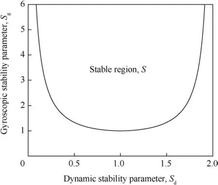
Fig.2.The stable region S.

The stable region is illustrated in Fig.2.
3.Optimization problems for mass distributions
The bullet model presented in Section 2 is next employed in the optimization of the mass distributions of a long range bullet and a limited range training bullet.Optimization problems are formulated for both types of bullet using the mass distribution vectorρas a decision variable.The objective functions and constraints reflect the desired stability characteristics.Throughout the paper,a value of 1.225 kg/m3is used for the air densityρair.The Mach number is computed based on the speed of sound having a value of 340 m/s.
3.1.Long range bullet
A long range bullet is intended to fly as far as possible without excessive dispersion.Therefore,the goal is to find a mass distribution such that the bullet stays stable with the lowest possible velocity.That is,the values of the gyroscopic and dynamic stability parameters should be inside the stable region S defined by Eq.(18)with the lowest possible velocity.
Decision variables of the optimization problem are the velocity when the bullet changes its state from stable to unstable,referred to as the unstable velocity vuns,and the elements of the mass distribution vectorρexcluding the shell of the bulletρ0.These elements,i.e.,the mass densitiesρiof the cells of the discretized core,are constrained between ρlb=1.225·10-3g/cm3and ρub=20 g/cm3.The lower bound is determined by the air density and the upper bound corresponds to densest metals available in the construction of the bullet.The number of cells in the core is n=400.The upper bound for the unstable velocity vunsis the initial velocity v0and the minimum bound is zero.The objective function of the optimization problem to be minimized is the unstable velocity vuns,i.e.,

The optimization problem is constrained so that the bullet must be stable at the beginning of its flight.In other words,with the initial velocity v0and the corresponding initial spin rate p0,the values of the stability parameters at the launch of the bullet,i.e.,the initial stabilities,denoted byand,must lie inside the stable region defined by Eq.(18).As the bullet exits the stable region with the unstable velocity vuns,the values of the stabilities with that velocity,denoted byand,must be on the boundary of the stable region,which defines the second constraint.The total mass of the bullet is constrained to the value of 20 g.To summarize,the constraints are
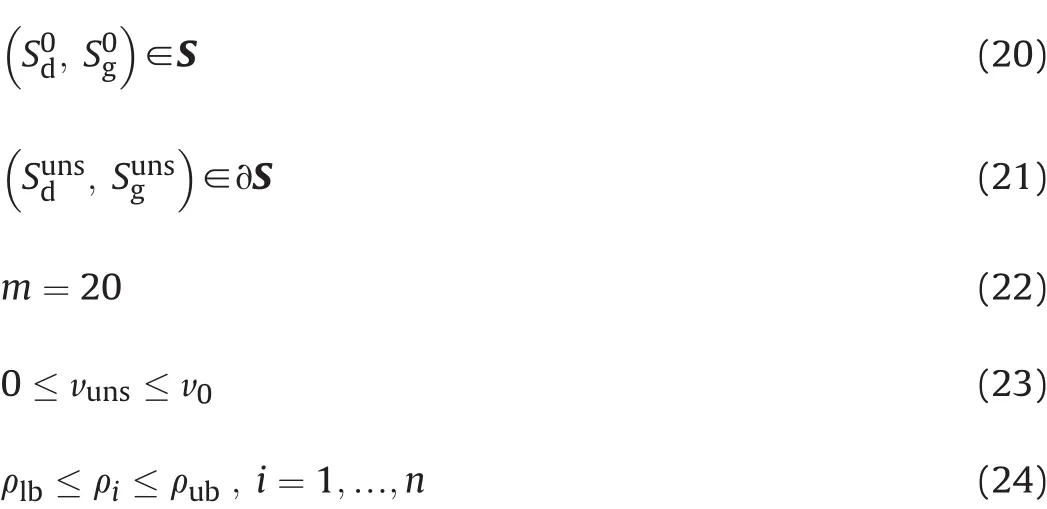
The constraints(20)and(21)follow from Eq.(18)defining the stable region.Here,∂S refers to the boundary of the stable region.The values of the stability parameters at the launch and the unstable velocity are calculated using Eqs.(14)and(16).The mass distribution vectorρaffects the moments of inertia Ixand Iyas well as the center of gravity xcgas described in Appendix A,and their values are used when calculating the stability parametersand.Varying the ‘unstable velocity’decision variable vunshas an impact on the stability parametersand
The parameters of the long range bullet are presented in Table 1.These parameter values are typical for long range bullets used with common sniper rifles.The initial spin rate is defined by the rifling of the firearm according to Eq.(1).The twist rate is selected to be 10 inches per one revolution.
3.2.Training bullet
The limited range training bullet should remain stable only for a short amount of time of its flight and then become unstable.When examining the values of the stability parameters,the bullet should be in the stable region S,depicted in Fig.2,at the beginning of the flight.When the velocity has decreased to a certain fixed velocity vref,referred to as the reference velocity,the values of the stability parameters should be as far as possible from the stable region.A value of 600 m/s is used for vrefthrough the whole analysis of thetraining bullet.The effect of the reference velocity on optimization results is discussed in Appendix B.

Table 1 Parameters of the bullet model used for the long range bullet.
The objective function of the optimization problem is the distance between the values of the stability parameters at the reference velocity vref,referred to as the reference point and denoted by,and the nearest point of the boundary of the stable region,denoted by.Decision variables are the elements of the mass distribution vectorρexcluding the shellρ0and the nearest point,i.e.,.The core consists of 400 cells.Bounds of the elements of the mass distribution vector are ρlb=1.225·10-3g/cm3and ρub=20 g/cm3.The maximization of the distance betweenandleads to the objective function

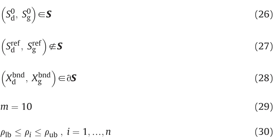
The constraints(26)-(28)follow from Eq.(18)defining the stable region.The values of the stability parameters at the launch and at the reference velocity vrefare calculated using Eqs.(14)and(16).As in the case of the long range bullet,the mass distribution vectorρaffects the moments of inertia Ixand Iyas well as the center of gravity xcgas described in Appendix A,and their values are used when computing the stability parametersand
The parameters of the training bullet are listed in Table 2.They are chosen to match common assault rifles and their bullets.The bullet is smaller compared to the long range bullet and has also lower initial velocity v0and spin rate p0.The initial spin rate is determined according to Eq.(1).The twist rate is 12 inches per one revolution.
3.3.Numerical solution
Computations are carried out and the optimization problems are solved using MATLAB R2015b[17]and its Optimization and Global Optimization Toolboxes.Since both problems are nonlinear and constrained,the fmincon function of Optimization Toolbox is used.The fmincon function is set to search the optimum with an interiorpoint algorithm[15].As neither optimization problem is convex,fmincon is only guaranteed to converge to a local optimum.In order to obtain the global optimal solution,a global search algorithm[16]via the GlobalSearch function of Global Optimization Toolbox is also employed.The underlying idea of the global search algorithm is to generate numerous potential initial iteration points,from which the interior-point algorithm is selectively run.
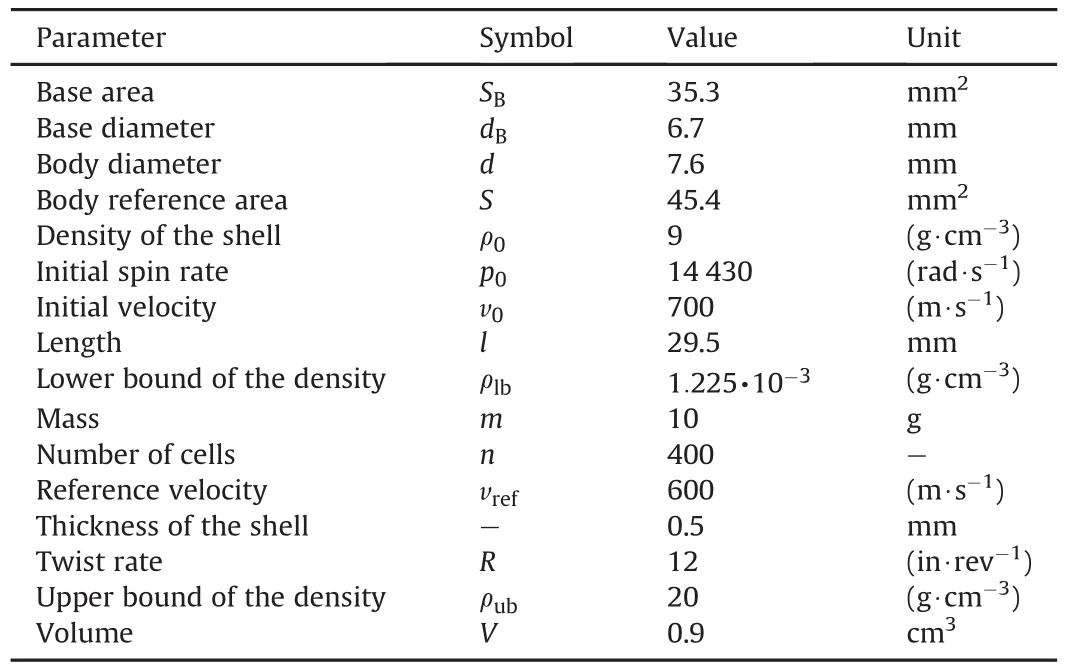
Table 2 Parameters of the bullet model used for the training bullet.
The optimization of the training bullet is a maxmin problem including two optimization tasks.The nearest point of the stable regionis not computed directly via optimization algorithms,since this would lead to a large computational load.Instead,300 points on the boundary of the stable region between Sdvalues of 0.1 and 1 are pre-computed.Then,within every iteration of the interior-point algorithm,the value of the reference pointand the distances between this value and the precomputed points are calculated.At each iteration,the precomputed point having the shortest distance to the reference point is selected to be the nearest point.Based on preliminary numerical experiments not discussed in this paper,the use of the pre-computed points does not affect the resulting optimal solutions significantly but speeds up the optimization considerably.The interval ofvalues,0.1<<1,and the amountof the pre-computed points,300,are also selected based on these preliminary experiments.
4.Optimal mass distributions
4.1.Long range bullet
The optimal mass distribution of the long range bullet is presented in Fig.3.The optimal value of the objective function is vuns=536.7,i.e.,the bullet becomes unstable at that velocity.In the optimal solution,almost all of the mass is packed to the rear part of the bullet alongside the shell,and the front and middle parts are empty.The solid mass at the rear has the highest density allowed,i.e.,20 g/cm3.

Fig.3.The optimal mass distribution of the long range bullet.The color of a cell represents mass density.Darker color indicates higher density.
The values of the stability parameters during the flight of the bullet with the optimal mass distribution are presented in the-coordinate system in Fig.4.The values at the launch are=0.97 and=3.68,so the bullet is clearly stable with its initial velocity and spin rate.At the unstable velocity,the values are=0.10 and=5.14.The bullet turns unstable at a low positive value of the dynamic stability parameter,as the gyroscopic stability increases during the flight.
4.2.Training bullet
The optimal mass distribution of the limited range training bullet is presented in Fig.5.The optimal value of the objective function,i.e.,the distance between the reference point at the reference velocity of 600 m/s and the nearest point of the boundary of the stable region is 0.253.In the optimal solution,all the mass is packed at the front and rear parts of the bullet,leaving the middle part empty.The mass at both ends has the highest possible density,i.e.,20 g/cm3.
The values of the stability parameters during the flight are shown in Fig.6.The bullet is only stable at the launch when it lies on the boundary of the stable region with the initial stabilities=0.54 and=1.26.When its velocity decreases,the bullet immediately exits the stable region and turns unstable.At the reference point,the values of the stability parameters are=0.18 and=1.44.
Recall that the value chosen for the reference velocity is 600 m/s.However,the nature of optimal mass distributions remains similar despite the choice of the reference velocity when considering supersonic velocities.This argument is verified in Appendix B where optimal mass distributions with different values of the reference velocity are presented.

Fig.4.The values of the stability parameters during the flight of the long range bullet with the optimal mass distribution.Dots represent the values of the stability parameters with decreasing velocities from the initial velocity v0=800 m/s and have an interval of 50 m/s.The unstable velocity v uns=536.7 m/s is plotted with an asterisk.

Fig.5.The optimal mass distribution of the training bullet.The color of a cell represents mass density.Darker color indicates higher density.
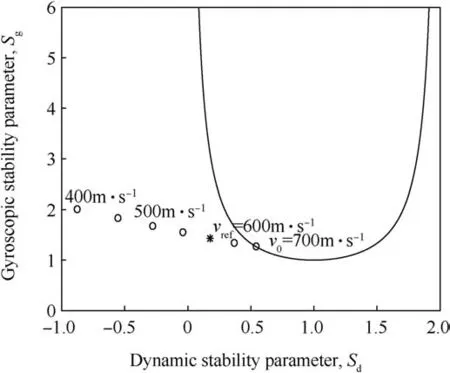
Fig.6.The values of the stability parameters during the flight of the training bullet with the optimal mass distribution.Dots represent the values of the stability parameters with decreasing velocities from the initial velocity v0=700 m/s and have an interval of 50 m/s.The reference velocity v ref=600 m/s is plotted with an asterisk.
5.Discussion
5.1.Nature of the optimal mass distributions
The optimization approach conveniently provides optimal mass distributions with respect to desired stability characteristics as demonstrated in Section 4.The optimal mass distribution for the long range bullet is to have all the mass at the rear end of the bullet against the shell(see Fig.3).On the other hand,the optimal mass distribution of the limited range training bullet has the mass packed to both ends of the bullet(see Fig.5).
For both bullets,the optimal mass distributions affect the stability parameters mainly via the Magnus effect,which connects the horizontal and vertical planes aerodynamically due to the frictional phenomena of the flow[2].Thus,the angle of attack in the vertical plane(the angle between the spin axis and the velocity vector of the bullet)leads to an aerodynamic moment affecting the bullet in both the horizontal and vertical planes.The Magnus force is assumed to have an impact on especially the rear part of the bullet,and by changing the center of gravity,the magnitude of the moment the Magnus force causes can be controlled.The Magnus moment is smaller when the center of gravity is near the rear of the bullet and bigger when near the front.Thus,with the aforementioned assumption and the simplifications associated with the underlying aerodynamic theory[14],the optimal mass distribution for the long range bullet results in having all the mass in the rear end,and the training bullet has the center of gravity near to the center of the bullet.However,the optimal solutions are also affected by other aerodynamic forces and moments,and they do not result solely from the Magnus effect.For example,the contribution of pitch damping moments behaves vice versa with respect to the center of gravity compared to the Magnus moment.
The effect of the aerodynamic quantities provided by the analytical expressions presented in Section 2.2 on optimal mass distributions is studied through a sensitivity analysis.The optimal mass distributions are determined one by one with each of the quantities having a value of 10%above or below the value acquired from the analytical expressions,and also with every quantity having 10%higher or lower value.The results of the sensitivity analysis are presented in Appendix C.The basic shape of the resulting optimal mass distributions remains similar despite the varied values of the aerodynamic quantities.Thus,the optimization approach is robust regarding changes in these values,and the new expressions(3)-(13)are deemed to be valid when they are used in the optimization of bullets’mass distributions.
To conclude,the features of the optimal mass distributions obtained with the optimization approach can be explained and rationalized based on fundamentals of aerodynamics and exterior ballistics.Furthermore,the optimal shape of the mass distributions is not sensitive with respect to changes in the values of the aerodynamic quantities.Therefore,the new approach offers a valid way to support the design of mass distributions of bullets.
5.2.Comparison to bullets with a uniform core
The optimal mass distributions differ significantly from those of currently manufactured bullets.Typically,bullets have a shell and a uniformly filled core usually made of lead[23].Both the optimal solutions obtained in Section 4 include only the densest possible material allowed by the constraints(24)and(30)of the optimization problems,and the mass is packed to one or both ends of the bullet.
The values of the stability parameters for uniformly filled bullets,having otherwise identical parameters as the ones used in the optimizations,are presented for the long range bullet in Fig.7 and for the limited range training bullet in Fig.8 for comparison.Here,the training bullet with a uniform core refers to an actual bullet for which a limited range modification is sought.As the unstable velocity vunsof the long range bullet with a uniformly filled core is 612.5 m/s and with the optimized mass distribution 536.7 m/s,a significant difference is observed implying that the bullet with the optimal mass distribution stays stable longer during the flight.With,e.g.,a velocity of 550 m/s,the bullet with the optimal mass distribution is inside the stable region whereas the uniformly filled long range bullet is clearly outside the region,see Figs.4 and 7.The training bullet with a uniform core is slightly unstable at the reference velocity 600 m/s,i.e.,the reference point is near the stable region.With the optimal mass distribution,the training bullet is further outside the stable region and,thus,more unstable at the reference velocity.Furthermore,with,e.g.,a velocity of 650 m/s,the bullet with the optimal mass distribution is outside the stable region,but the uniformly filled bullet is still inside the stable region,see Figs.6 and 8.

Fig.7.The values of the stability parameters during the flight of the long range bullet with a uniform core.Dots represent the values of the stability parameters with decreasing velocities from the initial velocity v0=800 m/s and have an interval of 50 m/s.The unstable velocity v uns=612.5 m/s is plotted with an asterisk.
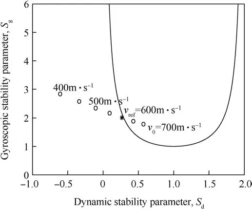
Fig.8.The values of the stability parameters during the flight of the training bullet with a uniform core.Dots represent the values of the stability parameters with decreasing velocities from the initial velocity v0=700 m/s and have an interval of 50 m/s.The reference velocity v ref=600 m/s is plotted with an asterisk.
5.3.Practical challenges of the optimal mass distributions
In real-life,mass distributions of bullets cannot be selected as freely as the formulations of the optimization problems introduced in Sections 3.1 and 3.2 allow.The manufacture of bullets may be difficult and too expensive,if their core contains holes or if their mass density varies greatly from one cell to another.Feasible mass densities may also be restricted to those of available materials.Furthermore,the interior ballistics has not been considered in this paper.The usability of a bullet poses structural limitations on its mass distribution.In particular,there are strong forces affecting the bullet at launch that set restrictions on the mass distribution.For example,the rear component of the optimal mass distribution of the training bullet would need more filling to support the shell in order to endure the forces the bullet experiences during the launch.
The above limitations regarding bullet design can be implemented by modifying upper and lower mass density bounds for the cells of a bullet's core denoted by ρlband ρubin Eqs.(24)and(30).The bounds can be defined separately for each cell if needed by specifying individual lower and upper bounds for the corresponding elements of the mass distribution vectorρ.For instance,too sparse cells in critical areas of the core can be avoided without limiting densities elsewhere by increasing the lower bounds for the elements corresponding to these areas.The mass densities of specific cells of the core can also be fixed to selected values prior to the optimization by using equality constraints.By utilizing these types of modified constraints,limitations posed by manufacturing techniques and real-life use of bullets can readily be taken into account in the optimization approach.
The use of mass density bounds discussed above and the optimization of mass distributions with commonly used bullet materials are illustrated in Appendix D.First,optimal mass distributions are determined such that the upper bound of mass density is set to correspond to steel,i.e.,7.85 g/cm3and the lower bound to the density of titanium,i.e.,4.51 g/cm3.Second,the same lower bound is used but the upper bound 11.34 g/cm3is specified by the density of lead.
5.4.Extensions of the optimization approach
The bullet model included in the optimization approach utilizes the closed-form representations for the aerodynamic coefficients and coefficient slopes as well as for the stability parameters based on the linearized equations of motions.Furthermore,the flight of bullets with optimal mass distributions is analyzed only at discrete velocities.Therefore,a potential avenue for future research is to investigate effects of the optimal mass distributions on flight performance in more detail by carrying out full 6-DOF trajectory simulations.Such simulations would provide the time history for the flight velocity,the spin rate and the yaw angle of the bullet with the optimal distribution.
The optimization approach could be applied to improve the flight performance of bullets with respect to terminal effects.The linear theory provides several relations for the launch and flight phase disturbances[2].These relations could be used in the formulation of mass distribution optimization problems for minimizing the disturbances which should ensure the desired terminal effects.The optimal mass distributions are determined in Section 4 for fixed parameters corresponding to established properties of currently used bullets.Thus,another line of future work is combining the optimization of the mass distribution and the external geometry details of a bullet.In this case,the dimensions of the bullet can also be treated as decision variables.However,the analytical expressions for the aerodynamic quantities presented in this paper are not alone sufficient for evaluating the properties of bullets with varying dimensions.Furthermore,current CFD technology is too computationally demanding to be utilized in this kind of optimization.Multi-objective optimization could also be employed in order to take into account,e.g.,material expenses in bullet design.The multi-objective optimization approach could reveal designs and structures of bullets such that their manufacturing is cost-efficient and flight performance is desirable.
In the future,the underlying ideas of the optimization approach presented in this papercould be applied in a simulation-optimization context.In this way,benefits enabled by the optimization and the use of6-DOFsimulationscan be merged.Thiskindofstudy could concern,e.g.,the mass distribution of a limited range training bullet such that the in fluence of the yaw angle on bullet aerodynamics is taken into account when maximizing the overall velocity deceleration.Other properties of bullets,e.g.,the effect of launch disturbance or in flight wind sensitivity on the impact point dispersion(e.g.[24]),could also be considered in 6-DOF simulation-optimization.
The optimization approach could also aid design work concerning bullets or projectiles containing an internal translating mass system or a non-solid core.An actively altered internal mass distribution might provide means to control the bullet flight[7].On the other hand,allowing some passive deformations in the internal mass,one might be able to adjust the stability properties and thus the in flight behavior of a bullet.Naturally,the optimization of such cores would require modifications to the bullet model presented in this paper.
6.Conclusions
The novel approach towards the optimization of internal mass distributions of spin-stabilized bullets was introduced.The mass distribution is optimized with respect to desired exterior ballistic properties that are expressed in the form of stability characteristics indicated by the gyroscopic and dynamic stability parameters.New analytical expressions for aerodynamic quantities were derived to address the compressibility of air.The approach contains a bullet model that allows for efficient computation of the stability parameters for a given discretized mass distribution.The model was employed in two nonlinear optimization problems for two types of bullets,i.e.,a long range bullet and a limited range training bullet.Objective functions and constraints of these problems reflect the goal of a bullet design process,i.e.,the desired stability characteristics whereas the discretized mass distribution is treated as a decision variable.The numerical solution of the problems was carried out with an interior-point algorithm and a global search algorithm.In this way,the global optimal mass distributions are obtained.
For the long range bullet,the optimal mass distribution was determined such that the bullet stays stable for as long as possible.The mass distribution of the training bullet was optimized according to the goal that the bullet is stable only for a short amount of time at the beginning of the trajectory.The resulting optimal mass distributions accomplish the pursued stability characteristics better than currently used bullets with a uniform core.Furthermore,the shapes of the optimal distributions are rationalized based on fundamentals of aerodynamics and exterior ballistics,and the validity of the new expressions of the aerodynamic quantities in the optimization of bullets’mass distributions is confirmed through sensitivity analysis.
The analytical exploration of mass distributions of bullets enabled by the new optimization approach has not been presented earlier in the literature.The approach is flexible in the sense that it readily permits versatile possibilities to modify and extend the optimization problems formulated in this paper.For instance,in the future along an increase of computing power,the combination of the mass distribution and the external shape details could be taken into account when designing a bullet that fulfills preferable stability and other prospective characteristics in the best possible way.Overall,the inherent idea of the optimization approach can be seen as a new goal focused philosophy for bullet design.That is,the goal of the design process is first defined,and then optimization is utilized in order to fulfill the predefined goal.The optimization approach clearly holds a lot of promise for improving bullet design and the design of other unguided airborne vehicles such as artillery shells or kinetic energy penetrators.
Nomenclature
CD0Zero-yaw drag coefficient
CDmaxDrag coefficient peak
CNαNormal force coefficient slope
CLαLift force coefficient slope
CmαPitching moment coefficient slope
CnpαMagnus moment coefficient slope
CmqPitch damping moment coefficient due to transverse angular velocity
Cm˙αPitch damping moment coefficient due to rate of change of angle of attack
d Body diameter(reference length)(mm)
dBBase diameter(mm)
IxAxial moment of inertia about the spin axis(kg m2)
IyTransverse moment of inertia about any axis perpendicular to the spin axis(kg·m2)
l Length(mm)
m Total mass(g)
Ma Mach number
n Number of cells
p Spin rate(rad/s)
p0Initial spin rate(rad/s)
P Cell vector
PiElement i of cell vector P
R Twist rate(in/rev)
S Body reference area(mm2)
SBBase area(mm2)
SdDynamic stability parameter
S Stable region
∂S Boundary of the stable region
t* Characteristic time(s)
v Velocity(m/s)
v0Initial velocity(m/s)
vrefReference velocity of the training bullet(m/s)
vunsUnstable velocity of the long range bullet(m/s)
V Volume(cm3)
ViVolume of cell Pi(cm3)
ρ Mass distribution vector(g/cm3)
ρ0Mass density of the shell(g/cm3)
ρairAir density(g/cm3)
ρiMass density of cell Pi(g/cm3)
ρ1bLower bound of the mass density(g/cm3)
ρubUpper bound of the mass density(g/cm3)
Appendix A.Computation of mass,center of gravity and moments of inertia
The bullet is considered in the three-dimensional Cartesian space ℝ3.The core of the bullet is discretized into n inner cells,denoted by Pi,i∈{1,…,n},and the shell is denoted by P0.The mass density is fixed within each cell and is denoted byρifor the cell Pi.Because each cell of the bullet is assumed to be rotationally symmetric around the spin axis,which is selected to be the x-axis,various quantities are more easily calculated in a cylindrical coordinate system.The total mass of the bullet is

where

The following auxiliary variable is introduced in order to calculate the center of gravity's position along the x-axis

where

The center of gravity is located at the point (xcg,0,0)=(mx/m,0,0).
In order to calculate the moments of inertia of the bullet,two more auxiliary variables are introduced,i.e.,

where

and

where

The bullet's axial moment of inertia about the spin axis is

The transverse moment of inertia about any axis perpendicular to the spin axis and passing through the center of gravity is

The variables Vi,,,andremain unchanged throughout the optimization of mass distributions.Therefore,it is sufficient to calculate them prior to the use of optimization algorithms,thus avoiding needless repetition of the same calculations.
At each iteration of the interior-point algorithm discussed in Section 3.3,the decision variables of the optimization problems(19)-(24)and(25)-(30)included in the mass distribution vectorρ are only used to calculate m,mx,mx2,and my2in Eqs.(A.1),(A.3),(A.5),and(A.7),respectively.Then,the values of these auxiliary variables are used when evaluating xcg=mx/m,Ixwith Eq.(A.9)and Iywith Eq.(A.10).This allows for efficient computation of the mass,the center of gravity,and the moments of inertia of the bullet during the optimization process.
Appendix B.Optimal mass distributions of the training bullet with different reference velocities
In the optimization problem of the limited range training bullet formulated in Section 3.2,the distance from the boundary of the stable region to the reference point given by the values of the stability parameters at the reference velocity vrefis maximized.The reference velocity is selected to be some velocity lower than the initial velocity of the bullet,and the value of 600 m/s is used in the optimization of the mass distribution of the training bullet in Section 4.2.
In order to be able to analyze the effect of the reference velocity on optimal mass distributions,the optimization problem for the training bullet discussed in Sections 3.2 and 4.2 is solved with several values of the reference velocity.The optimal mass distributions with the reference velocities of 550 m/s,500 m/s and 450 m/s are presented in Fig.B1.The nature of the optimal distribution remains similar despite changing the value of the reference velocity.Thus,the selection of the reference velocity does not affect the resulting optimal solutions significantly when using moderate supersonic velocities,and the use of the reference velocity 600 m/s is reasonable.
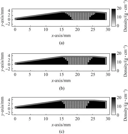
Fig.B.1.The optimal mass distribution of the training bullet using the reference velocity of a)550 m/s,b)500 m/s,and c)450 m/s.The color of a cell represents mass density.Darker color indicates higher density.
Appendix C.Sensitivity analysis
In the sensitivity analysis discussed in this appendix,optimal mass distributions for the long range and training bullets are determined with varied values of normal force coefficient slope CNα,zero-yaw drag coefficient CD0,pitching moment coefficient slope Cmα,Magnus moment coefficient slopeand the sum of pitch damping moment coefficients+.First,optimizations are carried out with all the values set at 10%above or below the ones acquired from the analytical expressions for the aerodynamic quantities presented in Section 2.2.Second,optimizations are conducted one by one with each of the quantities having a value of 10%above or below the value acquired from the analytical expressions.All other parameters of the bullet model are kept fixed at their original values presented in Tables 1 and 2
The resulting optimal mass distributions for the long range bullet and for the training bullet are illustrated in Figs.C1 and C2.The mass distribution of the long range bullet(Fig.C1)remains almost identical with the distribution(Fig.3)obtained with the exact values of the aerodynamic quantities Eqs.(3)-(13)despite the slight changes in these values.In the case of the training bullet,the resulting optimal mass distribution(Fig.C2)varies more but the basic shape remains similar and resembles the distribution(Fig.5)with the exact aerodynamic quantity values.Overall,the results of the sensitivity analysis reveal that the optimization approach presented in this paper is robust regarding changes in the values of the aerodynamic quantities.

Fig.C.1.The optimal mass distributions of the long range bullet with the slightly varied values of the aerodynamic quantities.
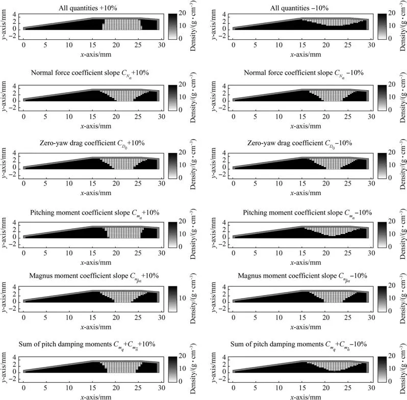
Fig.C.2.The optimal mass distributions of the training bullet with the slightly varied values of the aerodynamic quantities.
Appendix D.Optimal mass distributions with lead,steel and titanium
In the optimization problems presented in Section 3,the bounds of the mass densities of the cells were ρlb=1.225·10-3g/cm3corresponding to air andρub=20 g/cm3corresponding to dense metals,e.g.,tungsten.In this appendix,the bounds are set to values corresponding to commonly used materials,i.e.,lead(11.34 g/cm3)and steel(7.85 g/cm3)as well as to the density of titanium(4.51 g/cm3).Such bounds can be used for taking into account practical limitations and structural demands posed by bullets’manufacturing process and launch.Total masses of bullets are slightly varied compared to 20 g for the long range bullet and 10 g for the training bullet used in Sections 4.1 and 4.2 in order to allow optimal mass distributions to also contain lower densities than the maximum density only.All other parameters of the bullet model are kept fixed at their original values presented in Tables 1 and 2
In Fig.D1(a),the optimal mass distribution of the long range bullet is presented when the mass density upper bound corresponds to lead and the lower bound to titanium.The total mass of the bullet is 17 g.In Fig.D1(b),the upper bound is the density of steel and the lower bound is the density of titanium,and the total mass is 15 g.The optimal shapes of the mass distributions are similar to the optimal solution obtained in Section 4.1 where the maximum density corresponds to tungsten and the minimum density to air.Thus,the shape of the optimal mass distribution of the long range bullet is not sensitive to the material constraints.
The optimal mass distribution of the training bullet with the upper bound corresponding to lead and the lower bound to titanium is presented in Fig.D2(a).The total mass of the bullet is 8 g.In Fig.D2(b),the upper bound is defined by steel and the lower bound by titanium.The total mass of this bullet is 6.5 g.The optimal shapes of the mass distributions differ from the optimal distribution computed with the densities of tungsten and air in Section 4.2.However,the nose of the bullet consists of the densest materials in both cases.The mass in the body and the boat tail is distributed differently depending on the maximum and minimum mass densities allowed.
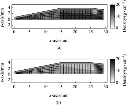
Fig.D.1.The optimal mass distributions of the long range bullet.The lower bound ρlb=4.51 g/cm3 corresponds to the density of titanium.The upper bound of mass density is a)ρub=11.34 g/cm3 corresponding to lead and b)ρub=7.85 g/cm3 corresponding to steel.

Fig.D.2.The optimal mass distributions of the training bullet.The lower boundρlb=4.51 g/cm3 corresponds to the density of titanium.The upper bound of mass density is a)ρub=11.34 g/cm3 corresponding to lead and b)ρub=7.85 g/cm3 corresponding to steel.
杂志排行
Defence Technology的其它文章
- Fluorine-containing oxidizers for metal fuels in energetic formulations
- On the formation of Basu's Type III(peeled orange)gunshot residues
- Interaction of TATB with Cu and Cu+1.A DFT study
- Crystal lattice free volume and thermal decomposition of nitramines
- Tribological and vibrational characteristics of AISI 316L tested at elevated temperature and 600 Torr vacuum
- Underwater explosion effects of 60 mm H.E.mortar bomb on a cylindrical concrete structure-PIT
