Application of Monte Carlo method to calculate the effective delayed neutron fraction in molten salt reactor
2019-02-27GuiFengZhuRuiYanHongHuaPengRuiMinJiShiHeYuYaFenLiuJianTianBoXu
Gui-Feng Zhu·Rui Yan·Hong-Hua Peng·Rui-Min Ji·Shi-He Yu·Ya-Fen Liu·Jian Tian·Bo Xu
Abstract Delayed neutron loss is an important parameter in the safety analysis of molten salt reactors.In this study,to obtain the effective delayed neutron fraction under flow condition,a delayed neutron precursor transport was implemented in the Monte Carlo code MCNP.The moltensalt reactor experiment(MSRE)model was used to analyze the reliability of this method.The obtained flow losses of reactivity for235U and233U fuels in the MSRE are 223 pcm and 100.8 pcm,respectively,which are in good agreement with the experimental values(212 pcm and 100.5 pcm,respectively).Then,six groups of effective delayed neutron fractions in a small molten salt reactor were calculated under different mass flow rates.The flow loss of reactivity at full power operation is approximately 105.6 pcm,which is signi ficantly lower than that of the MSRE due to the longer residence time inside the active core.The sensitivity of the reactivity loss to other factors,such as the residence time inside or outside the core and flow distribution,was evaluated as well.As a conclusion,the sensitivity of the reactivity loss to the residence time inside the core is greater than to other parameters.
Keywords Monte Carlo·Effective delayed neutron fraction·Molten salt reactor
1 Introduction
The effective delayed neutron fraction(DNF)describes the fission fraction from delayed neutrons,and it is an important parameter of reactor safety analysis,typically given in the basic unit of the reactivity($).Several efforts have been devoted to the measurement[1,2]and calculation[3,4]of the effective DNF.In general,the effective DNF is determined by the type of fissioning nuclides,the forward flux,and the adjoint flux.In molten salt reactors(MSRs),the flow of fuel salt can result in the redistribution of delayed neutrons;hence,it affects the effective DNF.The delayed neutron loss has already been an important issue in the MSR safety analysis[5-7].
Until now,a variety of calculation methods of the effective DNF in MSRs have been developed[8-10].An analytical algorithm for the bare cylinder reactor model was introduced by Oak Ridge National Laboratory(ORNL)under steady-state neutron distribution to obtain the effective DNF[11].However,several uncertainty factors are present in this method,such as the effect of the molten salt plenum,the velocity difference in the radial direction,and the uncertainty of the processed nuclear data.Since the beginning of the twenty- first century,signi ficant progress has been achieved in two-dimensional and three-dimensionalneutronic-thermohydrauliccoupling simulations[12-14].In these models,the flow behavior of the delayed neutron precursors(DNPs)has been considered,and the reactivity losses at different flow rates can be calculated more accurately.At the same time,a Monte Carlo method combined with a fluid model of DNP has been developed[15,16].The basic principle of the method is that if the startup particle is identi fied as a delayed neutron,then a DNP transport is performed to generate a redistribution of the delayed neutron source.The Monte Carlo method,which is a more accurate treatment containing less approximations and has strong adaptability in geometry,is especially suitable for nuclear design of novel reactor types.
We developed a direct statistics method in the Monte Carlo N-Particles Transportation code(MCNP)[17]to calculate the effective DNF of a molten salt reactor with solid fuel[18]and validated it using several benchmarks from the International Criticality Safety Benchmark Evaluation Project(ICSBEP).In this paper,the implementation of the DNP flow model within the MCNP code is presented.In this work, first,the accuracy of this method was validated using the measurement data from the molten-salt reactor experiment(MSRE).Then,the three-dimensional Monte Carlo simulation of the effective DNF in a small molten salt reactor(SMSR)was performed.At the same time,the sensitivity to factors,such as the flow velocity distribution in the radial direction,the DNP distribution in the upper plenum,and the residence time inside or outside the reactor,was analyzed.Following the sensitivity analysis,a reliable effective DNF in the SMSR was recommended for the next transient safety analysis.
2 Calculation method
In this section,the two proposed approaches to calculate the effective DNF are described.
2.1 Point kinetics equations under fuel flow state
The point kinetics equations are commonly used in system analysis programs,such as RELAP5.The flow effect can be included in the DNP transport equation,which can be written as follows[10]:
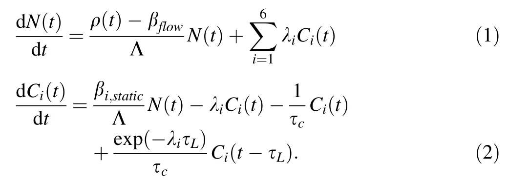
The first and second terms on the right-hand side of Eq.(2)are the fission generation rate and decay disappearance rate of precursors,respectively.The third term describes the flow disappearance rate,and the fourth term represents the recurrence rate.The residence time inside the reactor core is denoted by τc,while τLis the residence time outside the reactor core.The DNP concentration in the reactor core is denoted by Ci.The βi,staticvalue is the effective DNF under static state,which can be calculated by our previous method[18],while βflowis the effective DNF under stationary flow state.
In a stationary state,Eq.(1)becomes

and Eq.(2)can be written as

Combining Eq.(3)with Eq.(4),the effective DNF under stationary flow can be de fined as:

Although it is assumed that the DNPs have identical flow behavior and fission contribution in the point kinetics model in the equations above,the precursors at different positions and groups have different residence times and fission values.Typically,τcis regarded as the flow time from the inlet to the outlet,which is larger than the average residence time from the reactor core to the outlet.In addition,when the DNPs return to the reactor core,most of the delayed neutrons are located far from the central region with low fission value.For these reasons,the flow disappearance rate and the recurrence rate in the point kinetics model are underestimated.Furthermore,there is no clear boundary between the inside and outside of the reactor core.The commonly accepted treatment that considers the upper and lower plena as the outside of the core overstates the reactivity loss.The above discussion presented certain limitations of the point kinetics model,and therefore in the following section,its combination with the MSRE model is described.
2.2 Monte Carlo method with DNP transport
The Monte Carlo method can realistically simulate the particle transport and tally all information at any point.Nevertheless,the primary aim of Monte Carlo codes,such as MCNP,is to obtain an eigenvalue solution within one neutron generation,and less attention is paid on the information transmitted between neutron generations.The effective DNF exactly describes the fission contribution from the last neutron generation(see Fig.1).To calculate the effective DNF of the MSR,three steps need to be performed in the MCNP code.
In step one,the information on the type of fission neutron needs to be transmitted between neutron generations.In the MCNP code,the type of fission neutron(prompt or any group of delayed),can be obtained at the time of the sampling of the fission reaction.The particle information,such as coordinates,energy,cell number,and particle serial number,is stored in the one-dimensional vector fso and used in the next generation.The length of the fso vector can be expanded to store additional types of fission neutrons.

Fig.1 Monte Carlo neutron transport between generations
In step two,if the fission source point,whose information is obtained from the fso vector in the previous generation,is produced by a delayed neutron,the DNP transport needs to be performed before the neutron transport,to generate a new neutron source point.This transport depends on the velocity field of the molten salt.In this study, fitting field functions are used to replace the velocity field calculated with a fine mesh in the computational fluid dynamics(CFD)code,because velocity field calculations require signi ficant memory and computing time.There is one field function for every reactor component.First,the transport time T of each DNP is sampled according to the half-life of delayed neutron groups.Then,the positions of the DNP and the reactor component where it is located are found to determine which fitting field function needs to be called.Next,the residence time t in the component is calculated.If T is less than t,the final location of the delayed neutron in this component can be obtained.Otherwise,the transport time T needs to be set as T-t,and the previous steps need to be repeated in the next component,until T is less than zero.It should be noted,that after finding the new neutron source point,the cell number needs to be adjusted accordingly,or a fatal error of neutron loss arises in the neutron transport.
In step three,the fission contribution from different types of neutron sources needs to be classi fied and counted.As an example,for one delayed neutron source of type tp1(group 1)in generation N+1(as shown in Fig.1),there are four collisions during the transport history.It should be noted that the collision is based on the non-analog Monte Carlo model,in which the neutron does not disappear,but reduces the statistical weight until it is below a certain value.When an absorption collision occurs,the MCNP code further determines whether it is a fission reaction.As shown in Fig.1,three fission reactions occurwith statistical weights of(wtl,0-wtl,1),(wtl,1-wtl,2),and(wtl,3-wtl,4).The fission contribution from group 1 is the sum of these statistical weights.Finally,the effective DNF in one generation can be calculated as

where index i indicates the type of the fission neutron source,with prompt neutrons denoted by ‘‘0'',j indexes the number of collisions in one neutron history,l is the neutron number in one generation,and|f,tpiindicates that all statistics results only from fission collision and the i-type of fission neutron source.Owing to the dependency between neutron generations(as shown in Fig.1,tp4not only results from tp1,but also from tp3),for each fission reaction,15 generations of neutron sources are tracked.
3 MSRE model and veri fication
3.1 MSRE model
The MSRE was an experimental molten salt reactor went critical in 1965 and operated until 1969,and signi ficant operational data were obtained from it.These data are widely used as benchmark to verify the accuracy of newly developed MSR codes.The reactor model of the MSRE is shown in Fig.2.An equivalent cylindrical treatment is performed on the upper and lower plena,and further geometric parameters are taken from the design report[19]of ORNL.Certain geometric values and material parameters used in this model are shown in Tables 1 and 2.In this section,the effective DNFs of both U-235-based fuel and U-233-based fuel are calculated using the two methods explained above(Sect.2)and compared with the experimental values.

Fig.2 MCNP model of MSRE

Table 1 Geometry and parameters of the MSRE model
The flow time in each component of the MSRE is taken from the literature[20],as shown in Table 3.The velocity of the fuel salt is assumed uniform in each component.To study the effect of the upper and lower plena on the effective DNF,two cases are considered in the MCNP model.Case one,labeled as the MC Core model,assumes that the neutron importance is zero if the delayed neutron is outside the core,and case two,labeled as the MC Reactormodel,assumes that the neutron importance is zero if the delayed neutron is outside the reactor model.

Table 2 Materials of the MSRE model

Table 3 Flow time in each MSRE component
The flow velocity in the radial direction is not constant,as discovered in the MSRE[21].The flow velocity in the central region is faster than that in the marginal region by 10-20%.The distribution function of the velocity in the radial direction is described by

the average velocity is 21.3 cm/s[12,14],and the shortest,longest,and average residence times inside the core are 6.4 s,8.65 s,and 7.8 s,respectively,which are all lower than 9.4 s,as described in the design report.There were no direct fluid measuring probes of any kind(velocity,pressure drop,etc.)installed in the MSRE core,and the flow rate was an inferred quantity,obtained from the measured temperature differences in the fuel and coolant loops.
It is necessary to determine the actual velocity in the MSRE core,because the residence time inside the active core has a signi ficant in fluence on the effective DNF.The residence time of 9.4 s is obtained from ORNL report[20],and it was calculated using the fuel salt volume(25 ft3≊0.708 m3)and the flow rate(1200 GPM≊0.0757 m3/s).However,the fuel salt volume of the active core in this study is obtained as 0.59 m3(1.664·0.71·0.71·π·22.4%).The difference can be attributed to the difference in heights used in different models.The height in ORNL report[20]is possibly the effective core height(78 in.≊198 cm),based on the extrapolation of thermal neutron flux.Therefore,the 9.4 s value is possibly the residence time inside the effective core,and it is expected to be suitable for the point kinetics model,while it is possibly not applicable in the Monte Carlo model.In addition,from the results of the literature[12,14],it can be concluded that the average residence time of 7.8 s inside the core is closer to actual value of the MSRE.The model with constant speed is de fined as MC Reactor(7.8 s)-1,and the model with velocity distribution in Eq.(7)is de fined as MC Reactor(7.8 s)-2.
3.2 MSRE results and analysis
In this section,the results obtained using the point kinetics model(Sect.2.1)and the Monte Carlo method(Sect.2.2)are compared with the measurement data of the MSRE and the deterministic results from the literature[22].In the kcode mode,450 generations and 100,000 particles in each generation were used,with the nuclear data library ENDF/B-VII.0.
First,the effective DNFs of U-235 fuel were calculated.As shown in Table 4,the effective DNF under static conditions is 690 pcm,calculated with the direct statistical method[18]without DNP transport.With the point kinetics model,the reactivity loss with a residence time of 9.4 s inside the core is 217 pcm,close to the measured value[21],212 pcm.Nevertheless,with a residence time of 7.8 s,the reactivity loss increases to 241 pcm,and the increase in the loss mostly results from group 4,group 3,and group 2.With the Monte Carlo method,the reactivity loss of the model considering the core only with a residence time of 9.4 s is 204 pcm.If the upper and lower plena are included in the model,the reactivity loss decreases to 157 pcm.This implies that the delayed neutrons in upper and lower plena also have a non-negligible contribution to the effective DNF.However,the reactivity loss signi ficantly differs from the measured value.When the residence time is 7.8 s,the reactivity loss is 218 pcm and 223 pcm with a non-constant velocity pro file,close to the measured value,212 pcm.The reactivity losses were also calculated with different deterministic methods in the framework of the EU project,MOST[12].The calculation condition was nearly the same to that of the MC Reactor(7.8 s)-2,with 21.3 cm/s average core velocity of fuel salt.The axial height was 166.37 cm for core and 17.15 cm for the upper and lower plena.A number of results approximate the experimental value, while others are overestimated.
The effective DNFs with U-233 fuel are shown in Table 5.The reactivity loss using the Monte Carlo method is 100.8 pcm,which is in good agreement with the experimental value[21]of 100.5 pcm,which further confi rms that the Monte Carlo method for calculating the effective DNF under flow conditions is reliable.In theMOST project,several results have obvious differences with the experimental value.

Table 4 Effective delayed neutron fraction in the MSRE with different methods(235U fuel)

Table 5 Effective delayed neutron fraction in the MSRE with different methods(233U fuel)
Based on the analysis of the MSRE benchmark,the following conclusions can be drawn.(1)The point kinetics model needs to be used carefully.If the actual average residence time from inlet to outlet is adopted,the reactivity loss is overestimated.(2)The upper and lower plena need to be included in the calculation model for the Monte Carlo method.(3)The Monte Carlo method introduced in the MCNP is reliable.
4 SMSR model and analysis
4.1 Reactor model
The SMSR is an experimental MSR with LiF-BeF2-ZrF4-UF4fuel salt and graphite moderation.The fuel is 19.75 wt%enriched U-235.The enrichment of lithium-7 is required to be larger than 99.95%.The volume fraction of the fuel salt in the active core is 15%.Overall,there are more than 200 fuel salt,control rod,and test channels in the active core.
As shown in Fig.3,the SMSR is an integrated structure.The primary pump,heat exchanger,and pipelines are located in the reactor vessel.The heat exchanger is a shell and tube-type exchanger with fuel salt inside the shell.The flow order of the fuel salt in the core is from the lower plenum to upper plenum.A small part of the fuel salt passes through graphite gaps between graphite blocks.
As the geometry of the SMSR is complicated,it is not practical to build a complete CFD model for thermal hydraulic analysis.In this paper,the flow behavior in five components(active core,upper plenum,pump,heat exchanger,and lower plenum)is described by flow functions obtained from a CFD model considering a 1/12 section of the core,as shown in Fig.4.The fitting functions and flow time in different components are described as follows.

Fig.3 Layout of the SMRS
Active core The velocity distribution in the radial direction can be fitted by equation

with cm length unit.The fastest,slowest,and averaged residence times are 22 s,36 s(only occurring in a few edge channels),and 25.5 s,respectively.
Upper plenum The distribution of residence time can be fitted by equation

where v(R)is the flow velocity from channels in radial position R given by Eq.(8),z0is the semiminor axis of the upper plenum,and z is the relative position on the z-axis.If the z-position is determined,the radial position can be obtained by the elliptic equation
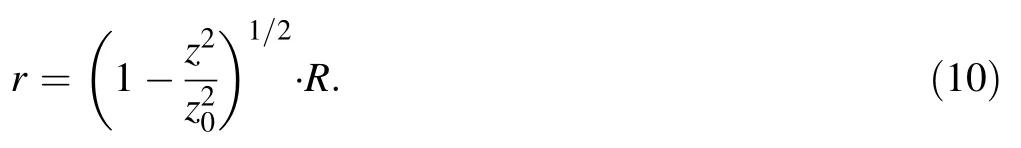
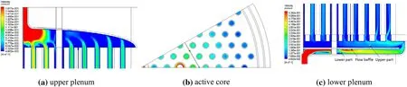
Fig.4 1/12 active core CFD model of the SMRS
The shortest,longest,and averaged flow times in the upper plenumare9.7 s,16.6 s,and11.9 s,respectively.Itispossible that Eq.(9)is not accurate.As the flow time in the upper plenum is non-negligible,as discussed in Sect.3,it is comparedwithaconstantvelocitymodelwitha flowtimeof11.9s.
Primary pump As the pump is far from the active core,we assume that the delayed neutrons are evenly distributed in the pump.The averaged flow time in the pump is 2.31 s,which is obtained from the fuel salt volume in the pump and the flow rate.
Heat exchanger The relationship between the time and z-position in the heat exchanger can be simpli fied to the function

where H is the total shell height of the heat exchanger.The total flow time thin the heat exchanger is 7.64 s.
Lower plenum The lower plenum is divided into two parts by a flow baf fle.For the lower part,the radial dependency of the residence time can be calculated from the volume and the flow rate,as

where G is flow rate and Hlis the height of each part.The averaged flow time in the lower part is 6 s.For the upper part of the lower plenum,the relationship between time and radial position is given by equation

Theshortestandlongest flowtimesintheupperpartare0 sand 7.7 s.The averaged flow time in the lower plenum is 11.8 s.
4.2 Results and discussion
4.2.1 Convergence

Fig.5 Statistical convergence of the delayed neutron fraction under flow in the SMSR
In this section,800 neutron generations and 500,000 particlesin each cycle were used in the MCNP calculation.The statistical convergence of the effective DNF under flow is shown in Fig.5.It can be considered steady after reaching 100 neutron generations,and the statistical standard errorat the 800th generation is approximately 2 pcm.
4.2.2 Density distribution of delayed neutron sources
The density distribution of the delayed neutron sources following the precursor transport can be tallied by the FMESH card in MCNP.As shown in Fig.6,the first four groups have a noticeable flow redistribution in the axial direction.The retention fraction in the primary pump is visible for the first three groups.Apparently,the upper and lower plena have a larger density of delayed neutrons than the active core,which is because the density of the delayed neutrons in the active core is averaged among the graphite and the fuel salt,which typically decreases the average precursor density to 0.145 times the value in the plena,containing only fuel salt.

Fig.6 Density distribution of the delayed neutron fraction in the SMSR
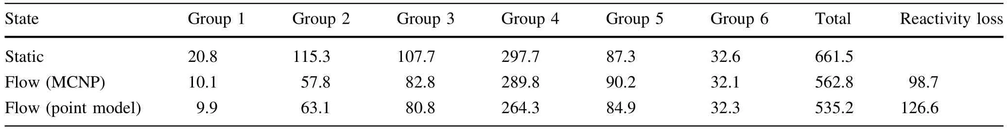
Table 6 Effective delayed neutron fraction in the SMSR under MCNP and point kinetics model

Table 7 Effective delayed neutron fractions in the SMSR under different flow masses
4.2.3 Effective delayed neutron fraction
As shown in Table 6,the effective delayed neutron fractions under static and flow state in the SMSR are 661.5 pcm and 562.8 pcm,respectively.The flow loss of reactivity is 98.7 pcm.If the point kinetics model is used,the reactivity loss is 126.6 pcm,larger than that obtained using the Monte Carlo method.Compared to that of the MSRE,the flow loss in the SMSR is signi ficantly lower due to the lower power density and longer residence time in the active core.The contributions to reactivity loss from groups 1-4 are 10 pcm,57.5 pcm,25 pcm,and 8 pcm,respectively.The loss ratio is signi ficantly larger for groups 1 and 2.
Under real conditions,the SMSR is expected to be operated at different power levels.As shown in Table 7,the reactivity loss is approximately proportional with the flow mass.
4.2.4 Sensitivity to other factors
The flow field of the SMSR is simpli fied in the calculations,which introduces several uncertainty factors.One part of the fuel salt fills the graphite gap of the reactor body,and its flow rate is signi ficantly slower than inchannels,which can change the residence time outside the active core.As showed in Table 8,the reactivity loss is insensitive to the residence time outside the active core.The reason for this is that the residence time inside the active core is very long,and therefore,the fraction of the delayed neutron precursors decaying outside and returning to the active core is very small.

Table 8 Effective delayed neutron fractions in the SMSR under different residence times outside the core

Table 9 Effective delayed neutron fractions in the SMSR under different residence time inside the core

Table 10 Effective delayed neutron fraction in the SMSR under different flow models
Furthermore,the bypass flow in the graphite gap increases the flow mass inside the active core to maintain a steady power output.The effective DNFs under different residence time inside the core are compared in Table 9.The reactivity loss has a noticeable increase at the lower residence times inside the active core.
Furthermore,the applied fitted flow function can introduce certain uncertainties in the value of the effective DNF.The results obtained with this model are compared with the results obtained with homogeneous( flow velocity)models(Table 10).In the core homogeneous model,the radial velocity is uniform.It is generally recognized that the reactivity loss in a homogeneous model is lower than in a heterogeneous model,because in the core,it results in a longer residence time of the precursors in the central channel with high fission value.However,the results in Table 10 are inverted,which is probably because the actual average residence time inside core in this heterogeneous model is larger than the residence time in the homogeneous model.Therefore,the actual reactivity loss in the SMSR can be slightly higher than 105.6 pcm.In addition,the homogeneous models in the upper and lower plena change the return time;however,this has little effect on the reactivity loss.From the calculation results of the MSRE,at the full power operation of the SMSR,we recommend 105.6 pcm for the flow loss of reactivity.
5 Conclusions
Our aim was to perform calculations to determine the effective delayed neutron fraction under flow conditions using a technique implemented within a Monte Carlo method.In this study,the DNP transport was implemented in the MCNP code.The MSRE model was used to analyze the reliability of this technique.The obtained flow loss of reactivity for U-235 and U-233 fuels is 223 pcm and 100.8 pcm,respectively,which are in good agreement with the experimentalvalues (212 pcm and 100.5 pcm,respectively).
Then,the same technique was applied to the SMSR under different flow masses.The flow loss of reactivity at full power operation is about 105.6 pcm.The sensitivity of the reactivity loss to other factors,such as the residence time inside or outside the core and flow distribution,was evaluated as well.The sensitivity of the reactivity loss to the residence time inside the core was found to be greater than to others parameters.
杂志排行

Nuclear Science and Techniques的其它文章
- Determination of water equivalent ratio for some dosimetric materials in proton therapy using MNCPX simulation tool
- Study of heat transfer by using DEM-CFD method in a randomly packed pebble-bed reactor
- Using monochromatic light to measure attenuation length of liquid scintillator solvent LAB
- Solution of the finite slab criticality problem using an alternative phase function with the second kind of Chebyshev polynomials
- Comparison of D- flip- flops and D-latches:in fluence on SET susceptibility of the clock distribution network
- Analysis of beryllium poisoning effect on liquid metal reactor with U-Be alloy fuel