Beam position monitors as precise phase pickups for beam energy measurement at the Compact Pulsed Hadron Source
2019-02-27MinWenWangQingZiXingShuXinZhengZhongMingWangMengTongQiuXiaLingGuanXueWuWangWenHuiHuang
Min-Wen Wang·Qing-Zi Xing·Shu-Xin Zheng·Zhong-Ming Wang·Meng-Tong Qiu·Xia-Ling Guan·Xue-Wu Wang·Wen-Hui Huang
Abstract The 13-MeV proton linac of the Compact Pulsed Hadron Source(CPHS)at Tsinghua University,China,is composed of a 50-keV electron cyclotron resonance proton source,a 3-MeV four-vane-type radio-frequency quadrupole(RFQ)accelerator,and a drift tube linac(DTL).Precise measurement of the beam energies at the exit of the RFQ and the DTL is critical for DTL commissioning.Two button-type beam position monitors(BPMs)installed downstream of the RFQ are used to perform the measurement using a time-of- flight method.The effects of several factors on phase measurement accuracy are analyzed.The phase measurement accuracy of the BPMs at CPHS is better than±1.03°at 325 MHz after corrections,corresponding to an energy measurementerrorof±0.07%.The beam energy measured at the exit of the RFQ is 2.994±0.0022 MeV,which is consistent with the design value.
Keywords Beam energy ·Time of flight·Beam position monitor·Phase pickup
1 Introduction
The Compact Pulsed Hadron Source(CPHS)is a compact proton and neutron source.As shown in Fig.1,it consists of a 50-keV electron cyclotron resonance proton source,two solenoids,correctors used for beam parameter matching,a 3-m-long radio-frequency quadrupole(RFQ)that accelerates the beam to 3 MeV,a drift tube linac(DTL)with permanent magnet quadrupoles to accelerate the beam up to 13 MeV,and a high-energy beam transport(HEBT)line to deliver the beam to the beryllium target[1].
CPHS has provided stable 3-MeV proton and neutron beams for more than 1500 h since the RFQ was commissioned successfully in March 2013.The 4.2-m-long DTL will be installed following the RFQ in 2018 to accelerate the proton beam to 13 MeV and therefore to further improve the neutron flux.The beam energies at the entrance and the exit of the DTL are critical parameters for setting the DTL working point.In other words,a beam energy measurement system is essential for the forthcoming DTL commissioning.Spectrometer[2-4]and time-offl ight(TOF)[5]methods are two commonly used methods.The spectrometer method needs an extra dipole magnet and a pro file monitor to perform the measurement,whereas the TOF method only needs two phase probes separated at a known distance.As shown in Table 1,fast current transformers(FCTs)and purpose-built phase probes are frequently used phase pickups for precise beam phase measurement.Although abutton-typebeam position monitor(BPM)is inherently a phase probe and has been used for phase measurement in some laboratories[6,7],reported studies on the phase measurement accuracy of BPMs are few.Given that two button-type BPMs[8]were already installed at the HEBT line,a feasibility study on using this pair of button-type BPMs as phase pickups to measure the proton beam phase and energy precisely without adding any more hardware is conducted.
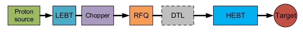
Fig.1(Color online)CPHS layout
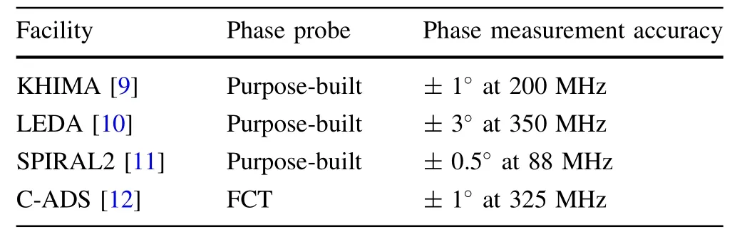
Table 1 Typical phase probes
2 TOF accuracy analysis
As shown in Fig.2,the BPM signals are transmitted from the tunnel to the electronics through coaxial cables of equal length.After undersampling,digital down-converting,and IQ demodulation,the signal phases from the two BPMs,φ1and φ2,with respect to a reference signal can be obtained from the IQ components.By assuming that the distance between the two BPMs is D,the beam velocity v can be written as

With the nonrelativistic beam energy of W=mv2/2,the relative measurement error of the TOF method is deduced as
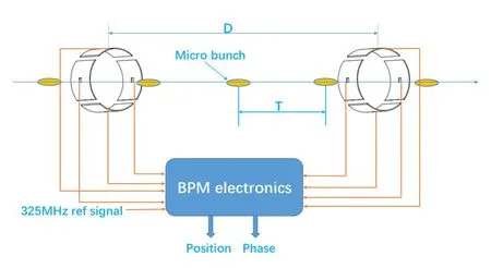
Fig.2(Color online)Schematic diagram of the TOF method

The energy measurement error is positively correlated with the distance error between the two BPMs,δD;the bunch number error,δN;the RF period error,δT;and the phase measurement error,δt.
δD is sum of measurement error of the distance between the two BPMs and the manufacturing error of the distance between fiducials and electrodes of the BPMs.Measured by a laser tracker,the measurement error is ensured to be<±0.2 mm at CPHS.Meanwhile,the manufacturing erroris required to be <±0.1 mm.Therefore,δD<± 0.3 mm in total.For D>2 m,the relative energy measurement error caused by δD is ≤ ± 0.03%.The measured beam energy will signi ficantly deviate from the design value if δN/=0,and,as will be shown in Sect.5,N can be measured accurately by observing BPM signals with an oscilloscope directly.Therefore,the energy measurement error from δN is avoidable.δT represents the master frequency deviation of the RF system,and δf is<1 ppm of the master frequency at CPHS[13].Therefore,the energy measurement error from δT can be neglected.
The phase measurement accuracy is affected by several factors,including signal coupling,signal transmission,and signal processing.Each step of these factors may result in phase measurement error.This will be discussed in Sect.3.
3 Phase measurement error analysis
3.1 Dependence on beam position
A button-type BPM is composed of four electrodes;i.e.,four signals can be obtained from one BPM.For an ideal BPM without mechanical errors,the phases of the first harmonic of the signals at individual electrodes are the same if the beam is centered.Consequently,the beam phase can be represented by either of them.By contrast,the signal phases at individual electrodes are different if the beam deviates from the center.This phenomenon can be attributed to two factors:(1)BPM interelectrode coupling and(2)the nontransverse electromagnetic field generated by the nonrelativistic beam.
To address the first factor,the equivalent circuit of a button-type BPM is shown in Fig.3.The signal induced at each electrode can be considered as a current source,whose amplitude depends on the beam displacement.Given the capacitive couplings between electrodes,the final signal on electrode i can be calculated as
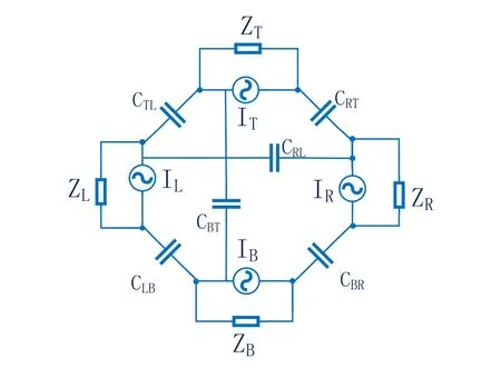
Fig.3 Equivalent circuit of a button-type BPM

where Ziis the impedance of electrode i and cijrepresents the coupling factor between electrodes i and j.
The BPM phase deviation from four pickups as a function of the beam displacement is shown in Fig.4.The circuit simulation results are consistent with the results of a CST PARTICLE STUDIO[14]simulation using a relativistic beam.The results show that the farther the distance between an electrode and the beam,the smaller the signal phase at the electrode.However,the phase of the summed signal is insensitive to beam displacement,which agrees with the MAFIA simulation results in Ref.[15].Explanations for the phenomenon are as follows:for an ideal BPM,ZR=ZT=ZL=ZB=Z.Then,from the point of view of the equivalent circuit,the summed signal is

where
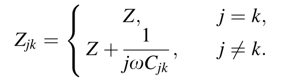
Because the electric field is perpendicular to the beam direction for a relativistic beam,four electrodes of the BPM couple the electric field generated by the displaced beam at the same time;that is,the phases of four image currents Ii(i=R,T,L,B)are the same.Therefore,the phase of the summed signal is insensitive to the beam displacement.
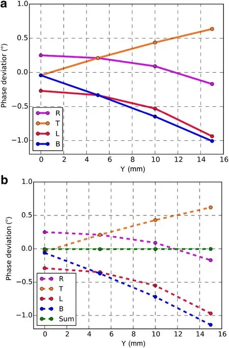
Fig.4(Color online)Phase deviation as a function of vertical beam position Y,with X being a constant of 5 mm.a Circuit simulation results.b CST simulation results using a relativistic beam
Now,let us address the second factor,also called the low-β effect.The electric field lines of a slow-moving beam have a finite longitudinal extent,and the longitudinal extent of the field lines is more along the beam pipe wall farther from the beam,as shown in Fig.5.Therefore,the farther an electrode is away from the beam,the earlier the electrode couples to the electric field generated by the beam.That is,the phases of the four image currents are different.Figure 6 shows the signal phases at each electrode for different displacements of a 3-MeV beam simulated with CST PARTICLE STUDIO.Compared with Fig.4,the phase deviation is larger at the same beam displacement,which means that the low-β effect has an impact on phase that is similar to that of the coupling effect.These two factors have combined to cause the dependency between the signal phase on an electrode and the distance from the electrode to the beam.None of the signal phases on the four electrodes re flects the real beam phase for an off-centered beam.Nevertheless,the phase of the vector sum of the four electrode signals is still insensitive to beam displacement,as presented in Fig.6.Therefore,the phase of the vector sum of the four electrode signals should be adopted to measure the beam phase with BPMs precisely.

Fig.5(Color online)Electric field distribution of a nonrelativistic beam.The red curves indicate the image current on the electrodes

Fig.6(Color online)Phase deviation versus vertical position Y simulated with a 3-MeV proton beam.X is a constant of 5 mm
3.2 BPM intrinsic offsets
Phase delays of each electrode of a BPM differ from each other because of machining and assembling errors.As shown in Fig.7,a BPM electrode can be modeled as a current source and a series RLC circuit connected in parallel[16].The phase delay of the electrode is determined by the impedance of the circuit.The output signal of the electrode can be calculated as

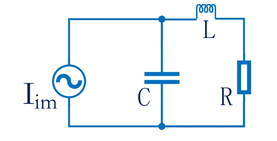
Fig.7 Circuit model of a BPM electrode
where ω is the angular frequency,R is the load resistor,C is the ground capacitance of the electrode,L is the inductance of the electrode,and Iim(ω)is the image current component on the electrode at a frequency of ω.Then the phase delay of the electrode is-arctan),where the minus sign is due to the de finition that the signal with a larger phase is prior to the signal with a smaller phase in the field of analog circuit.However,this study uses the opposite de finition.Possible mechanical errors are assigned to each electrode of the BPM1 and the BPM2 models randomly to perform a numerical experiment.A comparison between the circuit model method and the CST PARTICLE STUDIO simulation is given in Table 2.The maximum difference of the phase delays of the electrodes of the BPM1 and the BPM2 models between the two methods is<0.2°,verifying the effectiveness of the circuit model.
3.3 Difference in BPM phase responses
In the ideal case,the pair of BPMs used as phase pickups should have the same size and structure.However,in reality,the two BPMs used at CPHS have slight differences in electrode size and structure,and,consequently,the phase responses of the two BPMs are also different.The difference can be calibrated with a coaxial wire test bench described in the subsequent section.A 325-MHz RF signal was excited on the wire to simulate a beam,and the phase difference φ1between the two BPMs was measured.Then,the two BPMs were exchanged and the difference φ2was measured again.Then,the difference of the phase responses of the two BPMs is calculated as

3.4 Cables and electronics offsets
The BPM signals are connected,via several tens of meters of coaxial cables,to the Libera Single Pass H(LSPH)electronics[17].The electrical length of the cables for a given frequency may vary as a result of environmental changes.The degree of change is based on mechanical stress,connector torque,and thermal conditions.In this study,the two BPMs are only several meters apart and the cables almost face the same environment from the tunnel to the electronics,except for the first parts connecting to the BPMs.Therefore,observing the phase stability of the firstseveral meters of cables over flexure is critical and can be used to estimate the dynamic phase measurement error.The inconsistency of electronic channels is another error source.Because electronic channels and cables are usually used in pairs,they can be calibrated as a whole.With channel 1 as a reference,Table 3 presents the measured phase offsets of the eight channels of the LSPH.Phase variation over temperature is not considered in this study.Because only the differential phase of the two BPMs is considered,the absolute phase variation of each BPM has no effect.
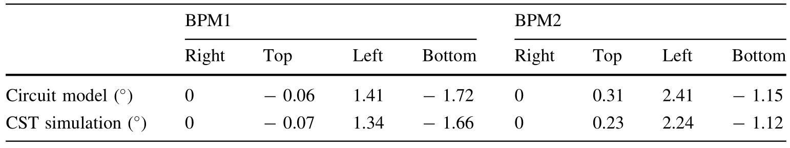
Table 2 Comparison of the calculated and simulated phase delays of electrodes of the BPM models
4 Off-line test
An off-line test was performed with a coaxial test bench to further verify the effectiveness of the circuit model and to measure the phase measurement accuracy of the two BPMs.Continuity of the impedance along the test bench is essential to minimize the amplitude of the re flected wave,which may cause phase difference error between the two BPMs.Given that the inner aperture of the beam pipe is 72 mm,a copper tube with a diameter of 33.4 mm was used as the inner conductor for impedance matching.Each side was a reducer that achieves the transition from thecoaxial transmission line to the N-type connector.A photograph of the test bench is shown in Fig.8.The parameters S11and S21of the test bench are measured by a vector network analyzer.As shown in Fig.9,the re flection and transmission losses are-34.2 and-0.19 dB at 325 MHz,respectively.The amplitude of the re flected wave is~2%of that of the incident wave,which may lead to a maximum phase difference error of 0.8°.
A 325-MHz signal was excited on one port of the test bench;meanwhile,a 50 Ω matched load ended the other port to con firm the phase measurement accuracy of the BPMs.The signal phase at each electrode of the two BPMs was measured by the vector network analyzer in sequence.The distance between the two BPMs was 174.6 mm.Given the propagation velocity of 0.998c in the test bench,c is the speed of light in the vacuum.The corresponding phase difference between the two BPMs was found to be 68.3°at 325 MHz.Given that the phase responses of the two BPMs are different,signals were measured by exchanging the two BPMs.From this measurement,the phase response difference of the two BPMs discussed previously can be measured.As shown in Fig.10,the measured phase differences from the four pairs of electrodes of the two BPMs are consistent with each other and the average phase difference was 68.53°± 0.28°,which is well matched with the ideal value 68.3°,verifying the proper construction of the test bench.The phase response difference of the two BPMs was calculated according to Eq.(6).By taking the electrode R as a reference,the difference was found to be 5.16°± 0.16°,as shown in Fig.11.
The intrinsic offsets of the two BPMs were also measured.The measured phase delays of each electrode of BPM1 and BPM2 are shown in Fig.12.By using a vector network analyzer(R&S ZNB20),the impedances of all the BPM electrodes at different frequencies,which are used to calculate the capacitances and inductances of each electrode,were obtained by measuring the parameter S11in the frequency domain.The measured capacitances and inductances of each electrode of the pair of BPMs at CPHS are presented in Table 4.By using the measured capacitances and inductances,the phase delays of each electrode are also calculated with the circuit model for comparison.With electrode R still taken as the reference,the measured phase delays are consistent with the phase delays calculated with the circuit model,which veri fies the effectiveness of the circuit model again.Therefore,measuring the capacitances and inductances of BPM electrodes with a network ana-lyzer,which is much easier than constructing an off-line test bench,is adequate for determining the intrinsic offsets of the electrodes resulting from mechanical and assembly errors.

Table 3 Phase offsets of the eight channels of the LSPH

Fig.8(Color online)Photograph of the off-line test bench
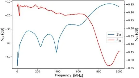
Fig.9(Color online)Re flection and transmission losses of the test bench
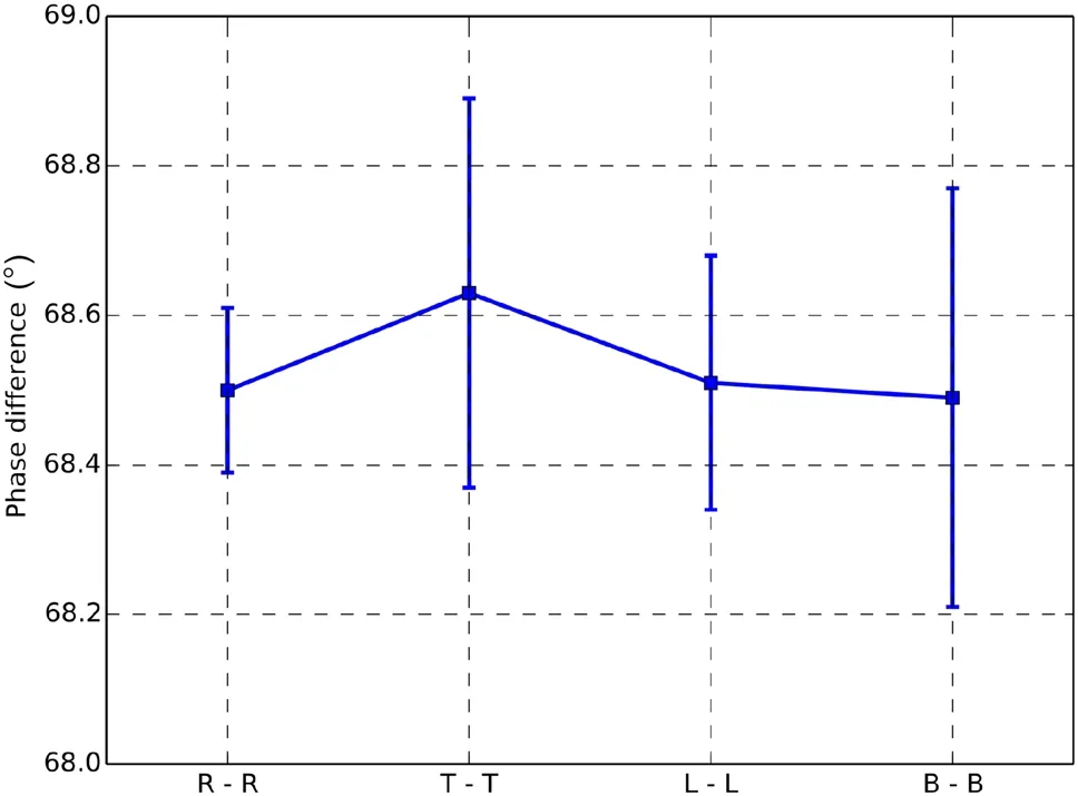
Fig.10 Measured phase differences from the four pairs of electrodes of the two BPMs

Fig.11 Histogram of the measured phase response difference of the electrode R of the two BPMs
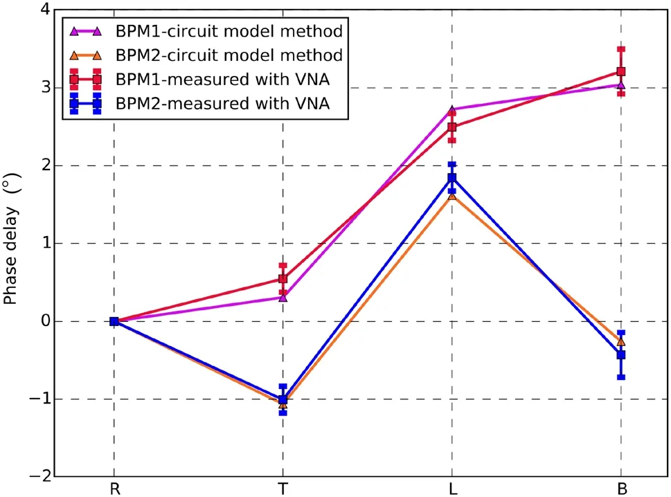
Fig.12(Color online)Comparison of the measured and calculated intrinsic offsets of the two BPMs
5 Experimental setup and results
Because the beam pulse structure becomes increasingly indistinct along the beam line because of energy spread,the BPMs should be installed close to the exit of the RFQ to acquire large BPM signals to guarantee high measurement resolution.As depicted in Fig.13,BPM1 is located 1681 mm downstream of the RFQ and BPM2 is 2213.3 mm away from BPM1.The system parameters are listed in Table 5.

Table 4 Measured capacitances and inductances of each electrode of the actual BPM1 and BPM2
Thus far,CPHS has functioned in a low-duty mode.A 40-μs-long flat-top beam,selected from a 400-μs-long beam at 50 keV by controlling the length and delay of the microwave fed into the RFQ,is accelerated to 3 MeV at a repetition rate of 50 Hz.A chopper was installed in the low-energy beam transport line to form a sharp edge in the beam longitudinal distribution,which is bene ficial to observe the first micro-bunch of the BPM signals.The TOF can be approximately measured by using an oscilloscope(Tek TDS7404B;10 GS/s).As shown in Fig.14,the time needed for the beam to move from BPM1 to BPM2 is between 92.4 and 92.8 ns,respectively,including 30 micro-bunches.
Eight signal phases from the two BPMs are measured with the LSPH electronics to achieve a more accurate measurement.The measured and corrected results are listed in Table 6.Although the corrected signal phases on the four electrodes ful fill the conclusion in Sect.3,the phase differences between electrodes caused by beam displacement are slightly larger than the simulation results,given that the beam positions at BPM1 and BPM2 are(4.7 mm,-1.0 mm)and(-6.0 mm,-0.5 mm),respectively.The maximum phase difference between electrodes resulting from the displacements should be≤ 1°according to CST simulation.Nevertheless,the actual maximum phase difference between electrodes is 2.06°for BPM1 and 1.88°for BPM2.Because the phase of the vector sum of the four electrode signals is adopted for beam position correction,the error in the phase will be not more than the maximum phase difference between electrodes.Although the large difference is worth studying further,the phase measurement errors resulting from the displacements are<±1.03°for BPM1 and<± 0.94°for BPM2.Given that the maximum measurement error of the phase response difference of the two BPMs is ±0.36°,the phase difference measurement error is<± 2.33°in total.Therefore,the measured phase difference is 31.5°± 2.33°,corresponding to a beam energy of 2.994±0.0022 MeV,which is consistent with the design value.
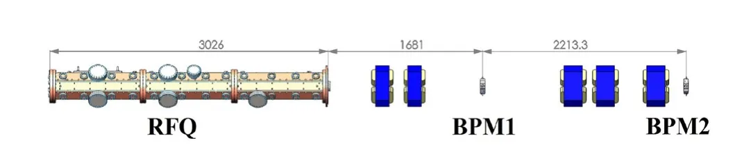
Fig.13(Color online)Experimental setup of the TOF measurement

Table 5 Parameters of the TOF system

Fig.14(Color online)Signals on the T electrodes of BPM1(in blue)and BPM2(in red)
Given that signal phases can be measured once per microsecond,beam energy jitter within a macro-bunch was investigated.The result is shown in Fig.15.The beam is stable,with energy variation within a macro-bunch being only~0.03%.The relation of the beam energy to the RF power fed into the RFQ was also studied.The beam energy measured at different feeding RF powers to the RFQ is shown in Fig.16.Near the design value,RF power fed into the RFQ has limited effects on the RFQ output energy.The variation trend of the curve is similar to the beam dynamics simulation result of the RFQ with the TraceWin code[18],but their shapes and absolute values are discrepant.More studies on the RFQ beam dynamics should be conducted to explain the discrepancy,which is beyond the scope of this paper.

Table 6 Measured and corrected signal phases from BPM1 and BPM2

Fig.15 Beam energy jitter within a macro-bunch
6 Summary
In this paper,energy measurement with an accuracy of±0.07%has been achieved using the TOF method with two button-type BPMs separated by an appropriate distance at CPHS.After accurate calibrations and off-line tests,the phase measurement accuracy of the button BPMs at CPHS is better than±1.03°at 325 MHz.The phase difference measurement errors that originate from beam displacements,BPM intrinsic offsets,phase response difference between BPMs,and offsets and noise of electronics and cables are analyzed,and corresponding correction methods are introduced.After these corrections are made,we find that the BPM can be a good option as a precise phase pickup and that an accelerator equipped with at least two BPMs has the capability of measuring beam energy precisely.

Fig.16(Color online)Relation between the input power of the RFQ and the beam energy
杂志排行

Nuclear Science and Techniques的其它文章
- Simulation study of the dose and energy responses of FNTD personal neutron dosimetry
- Using monochromatic light to measure attenuation length of liquid scintillator solvent LAB
- Solution of the finite slab criticality problem using an alternative phase function with the second kind of Chebyshev polynomials
- Determination of water equivalent ratio for some dosimetric materials in proton therapy using MNCPX simulation tool
- Application of Monte Carlo method to calculate the effective delayed neutron fraction in molten salt reactor
- Analysis of beryllium poisoning effect on liquid metal reactor with U-Be alloy fuel