Strong Current-Polarization and Negative Diflerential Resistance in FeN3-Embedded Armchair Graphene Nanoribbons
2019-01-10YingchaoWuJiaruiRaoXiaofeiLi
Ying-chao Wu,Jia-rui Rao,Xiao-fei Li
School of Optoelectronic Science and Engineering,University of Electronic Science and Technology of China,Chengdu 610054,China
Motivated by the recent advances of transition-metal-nitrogen-carbon(TM-N-C)materials in catalysis,we investigate the electronic structure and transport properties of FeN3-embedded armchair and zigzag graphene nanoribbons(FeN3@AGNRs,FeN3@ZGNRs)with diflerent widths.The first-principles results indicate that the FeN3induces significant changes on the band structures of both ZGNRs and AGNRs,making the resultant systems quite different from the pristine ones and own room-temperature stable ferromagnetic(FM)ground states.While only FeN3@AGNRs possess a significant spin-dependent negative diflerential resistance(NDR)and a striking current polarization(nearly 100%)behaviors,due to that FeN3introduces two isolated spin-down states,which contribute current with diflerent performances when they couple with diflerent frontier orbits.It is suggested that by embedding FeN3complexes,AGNRs can be used to build spin devices in spintronics.
Key words:Transition-metal-nitrogen-carbon,Current polarization,Electronic transport,Non-equilibrium Green’s function
I.INTRODUCTION
Transition-metal-nitrogen-carbon(TM-N-C)materials have received much attention recently,due to promising applications in catalysis[1–5]. Graphene possesses novel properties and wide applications[6].TM atoms can be loaded on graphene via adsorbing on defects or isolating at edges[7–11].The resultant TM-graphene can be either magnetic or nonmagnetic[12,13],depending on the type of TM atoms and the post-formed substructures.Nitrogen-doped graphene(N-graphene)can adequately confine a large number of TM atoms via various chemical activities,due to the existence of many N-doping induced activities[14–19].And experimental measurements show that the obtained TM-N-graphene could possess enhanced stability and comparable high catalytic activity to TM-graphene and to other TM-N-C materials[20].
Recently,we have proven that conversion of dinitrogen to ammonia is achievable in FeN3-embedded graphene(FeN3@graphene),due to the existence of a strong spin-polarization near Fe center[5,21].Previous studies suggest that the number of 3d electrons retained in TM center plays a critical role in determining the catalytic ability of TM-N-C systems[22],since they concern the strength of spin-polarization signi ficantly[15,23,24].A strong spin-polarization is also a highly desired property in spintronics.For instance,graphene nanoribbons(GNRs)have rich and extraordinary electronic properties,but only zigzag-edged GNRs(ZGNRs)are widely proposed for building spin devices,due to anti-ferromagnetic(AFM)edge states[25–27].On the contrary,armchair-edged GNRs(AGNRs)are intrinsically nonmagnetic and are hard to magnetize,and thus have rarely been proposed for spintronics[28–32].Hence,we are keen to know when FeN3complexes are embedded,whether the resultant FeN3@AGNRs and FeN3@ZGNRs are magnetized and whether both of them can be used for building spin devices.
In this work,the electronic structure and transport property of both FeN3@AGNRs and FeN3@ZGNRs with diflerent widths are evaluated from first principles calculations.Our results show that a significant spin-dependent diflerential negative resistance(NDR)and a striking current-polarization(near 100%)present only in FeN3@AGNRs,demonstrating the possible device applications of such systems in spintronics.
II.MODEL AND COMPUTATIONAL METHOD
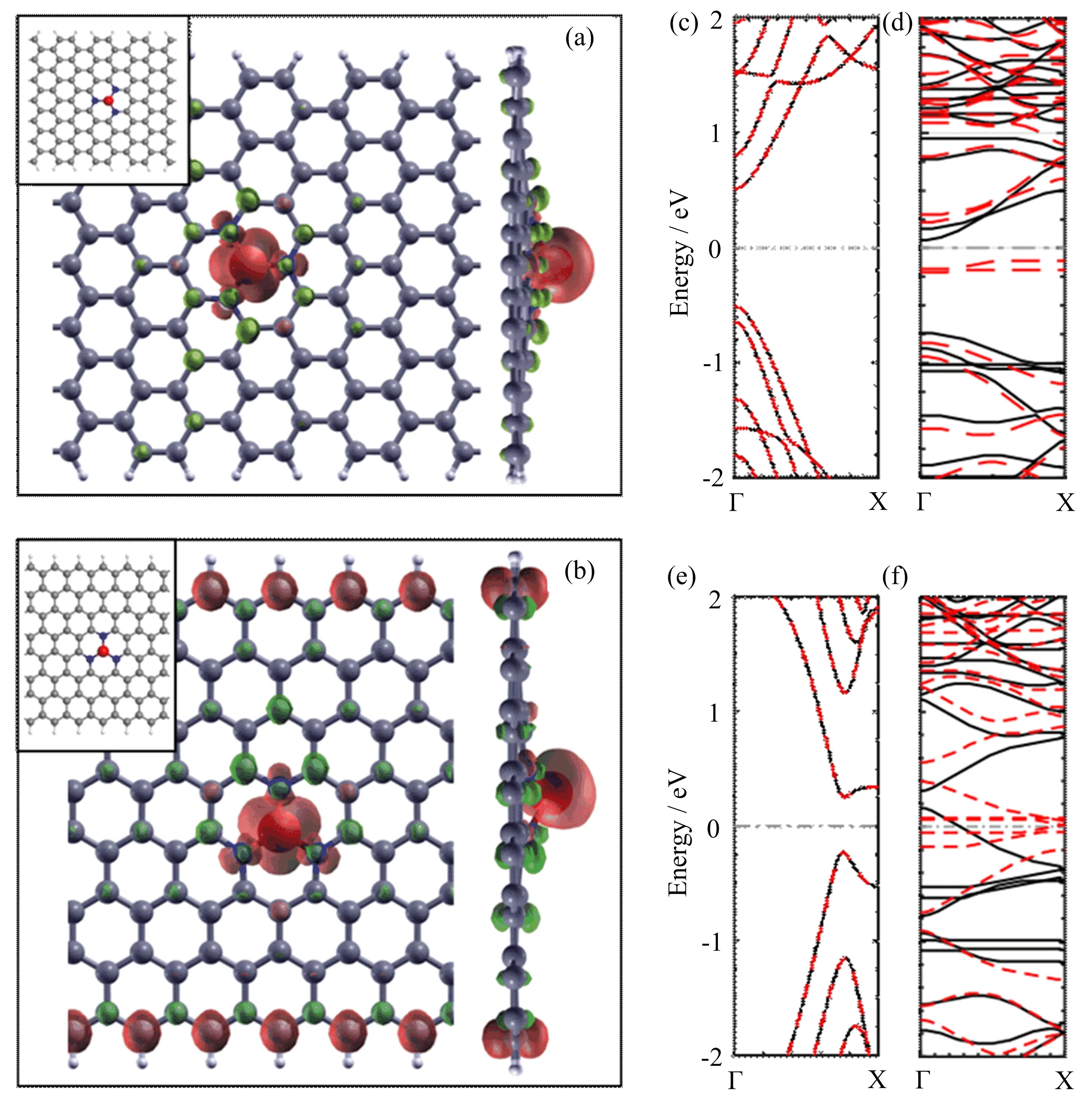
FIG.1 Top and side views of iso-surface plots of the spin-resolved charge density of FeN3@13-AGNR(a),and those of FeN3@8-ZGNR(b)(the red for spin-down and green for spin-up charge densities),with the iso-value set 0.02 e˚A−2,and the optimized structures of the FeN3@13-AGNR and the FeN3@8-ZGNR were given in the insets of FIG.1(a)and(b)in the upper left corner(the red,blue,gray,and white colors represent the iron,nitrogen,carbon,and hydrogen atoms),as well as the band structures of pristine 13-AGNR(c),FeN3@13-AGNR(d),pristine 8-ZGNR(e),and FeN3@8-ZGNR(f)(the red dotted lines for spin-down and the black solid lines for spin-up electrons),respectively.
Considering that AGNRs are classified into three families by their width-dependent energy gaps(W=3m,3m+1,3m+2)[25,26],three FeN3@AGNRs with width W=12,13,and 14 were investigated,whereas only an FeN3@ZGNR with W=8 was considered.To eliminate the periodic interaction,4 cells of AGNR and 6 cells of ZGNR were included in the supercells of the FeN3@AGNR and FeN3@ZGNR,which are of a length about 1.7 nm and 1.5 nm,respectively.The vacuum layer of a distance about 15˚A was used along x and y directions.As examples,the optimized structures of the FeN3@13-AGNR and the FeN3@8-ZGNR were given in the insets of FIG.1(a)and(b)in the upper left corner,respectively.
All the calculations were carried out in SIESTA code(Version 4.0),by applying nonequilibrium Green’s functions(NEGFs)in combination with the spin-resolved density functional theory(DFT)[33]. The revised Perdew-Burke-Ernzerhof(rPBE)generalized gradient approximation(GGA)was chosen for exchanging correlation potential.A 150 Ry cut-o ffenergy was set for real space grids.An energy shift parameter of 0.01 Ry was used to determine the cuto ffradii of atomic orbitals.A tolerance of 0.02 eV/˚A on each atom was used to control the residual force for structural relaxations.The grids of 1×1×11 and 1×1×23 were adopted to sample the Brillouin zone(BZ)for structural relaxations and band-structure analysis,and the grid of 1×1×100 for transport calculations,respectively.
III.RESULTS AND DISCUSSION
Total energy calculations show that the energy difference(∆E)for the FeN3@ZGNR between the ferromagnetic(FM)state and anti-ferromagnetic(AFM)state is about−0.94 eV,and that between the FM and nonmagnetic(NM)states is about−1.04 eV.Obviously,FeN3@8-ZGNR is still spin-polarized.Diflerent from the pristine ZGNRs,FM becomes the ground state which is quite stable at room temperature.Yet for FeN3@13-ANGR,the∆E between FM and NM states is about−0.82 eV and the AFM state is even not reached.Contrary to the pristine AGNRs,FeN3@AGNR is magnetic and has a room-temperature-stable FM ground state.Obviously,the embedding of FeN3brings a significant change on the electronic characteristics of GNRs,especially for AGNRs.

FIG.2 The band structures of FeN3@12-AGNR(a),FeN3@13-AGNR(b),and FeN3@14-AGNR(d),(red dotted lines for spin-down,and black solid lines for spin-up),as well as the normalized PDOS of FeN3@13-AGNR(c)(negative for spin-down and positive for spin-up)at their FM ground states.
The magnetic moments of FeN3@13-AGNR and FeN3@ZGNR at ground states are found to be 3.16µBand 5.0µB,and the iso-surfaces of the spin-resolved density of them are plotted in FIG.1(a)and(b),respectively.For the FeN3@AGNR,charge clouds distribute at the vicinity of the Fe atom and are localized above the surface,indicating that the main part of magnetic moment comes from Fe atom and only a very small part from the neighboring N atoms.While for the FeN3@ZGNR,the net electrons distribute both along the zigzag edges and near the FeN3center. Obviously,the net electrons on the two edges and the center have the same spin orientation,indicating that the embedding FeN3changes the interaction between the edge states of ZGNR from anti-ferromagnetic to ferromagnetic.The spin-resolved band structure of pristine 13-AGNR and FeN3@13-AGNR at the ground state is given in FIG.1(c)and(d),and that of the 8-ZGNR and FeN3@8-ZGNR in FIG.1(e)and(f),respectively.One can see that the embedding induces obvious spin-splits near the Fermi level for both FeN3@AGNR and FeN3@ZGNR.Their electronic structures are indeed modified drastically by the embedding.Especially for the FeN3@AGNR,there exist two isolated spindown states near the Fermi level,suggesting a strongly spin-dependent transport behavior.Since the valence band maximum(VBM)and conduction band minimum(CBM)play a decisive role in determining the transport properties.To provide a general view of the eflect of embedding on the band structures of the three families AGNRs.The band structures of FeN3@12-AGNR,FeN3@13-AGNR,and FeN3@14-AGNR are plotted in FIG.2(a),(b),and(d),respectively.One can see that although there exist some diflerences in the band gap of the three ribbons,they have a similar overall picture on the band structures.Especially,two isolated spin-down states below the Fermi level can be found in each ribbon,suggesting the similar spin-dependent transport properties of the three families of the embedded AGNRs.
For the sake of analysis,the projected density of state(PDOS)of the FeN3@13-AGNR is calculated and given in FIG.2(c).It shows clearly that the two isolated spin-down states are mainly derived from the 3d electrons of Fe atom and the 2p electrons of C atoms,unambiguously proving the origins of the observed FM ground state.This also means that some 3d electrons have transferred into graphene network via the three N atoms and thus contributed to electronic transport.More importantly,one can see that only the 3d electrons of spin-down orientation have a wide distribution in energy.Hence,the 3d electrons have a significant contribution only to spin-down transport.This feature is quite useful for spin-dependent transport.
We calculated electronic transport properties and the obtained current-voltage(I-V)characteristics of FeN3@13-AGNR and the pristine one are plotted in FIG.3(a).It shows clearly that the current of spindown system reduces rapidly as the bias increases from 0.9 V to 1.1 V,suggesting that the system possesses an obvious spin-dependent negative diflerential resistance(NDR)behavior,which is quite useful for building spindependent electronic switches.Moreover,one can see that the embedding induces only a significant reduction on the threshold voltage of the spin-down system from 1.0 V to 0.4 V,and thus the spin-down currents are much higher than the spin-up current for the biases below 1.1 V.This means that the system possesses a strong current-polarization(ξ),which can be defined as ξ=|IUP−IDN|/(IUP+IDN).We calculated the biasdependent ξ and the obtained result is plotted in FIG.3(b).For the bias from 0.2 V to 1.0 V,one can see perfect current-polarization with a ratio almost 100%,very advantageous for high-performance spin device applications.Considering the similar structures of the three families of FeN3@AGNRs,one can draw a conclusion that FeN3@AGNRs possess a striking currentpolarization and a large spin-dependent NDR behavior,which are quite useful in spintronics.
Curious about the underlying mechanism,we illustrated the contour of bias-dependent transmission T(E,Vb)of the spin-up and spin-down systems of the FeN3@13-AGNR in FIG.3(c)and(d),respectively,where the bias window for current calculations was marked by two white lines.For spin-up systems,one can see that meaningful transmission appears in the bias window only as the bias increases to 1.0 V,while for spin-down system,meaningful transmission starts to appear in the bias window as Vb=0.4 V,and it is retained to form a belt with bias increasing. Thus spin-down current in the bias ranging from 0.4 V to 1.0 V is always much larger than the spin-up current,which is almost zero,resulting in the striking currentpolarization.Noting that a valley exists in the formed transmission belt around Vb=1.0 V(denoted by a red arrow in the FIG.3(d)),indicating the smaller current at this region that well explains the NDR behavior of spin-down system.Hence,the formed transmission belt is significant for understanding both the observed NDR and current-polarization of the system.
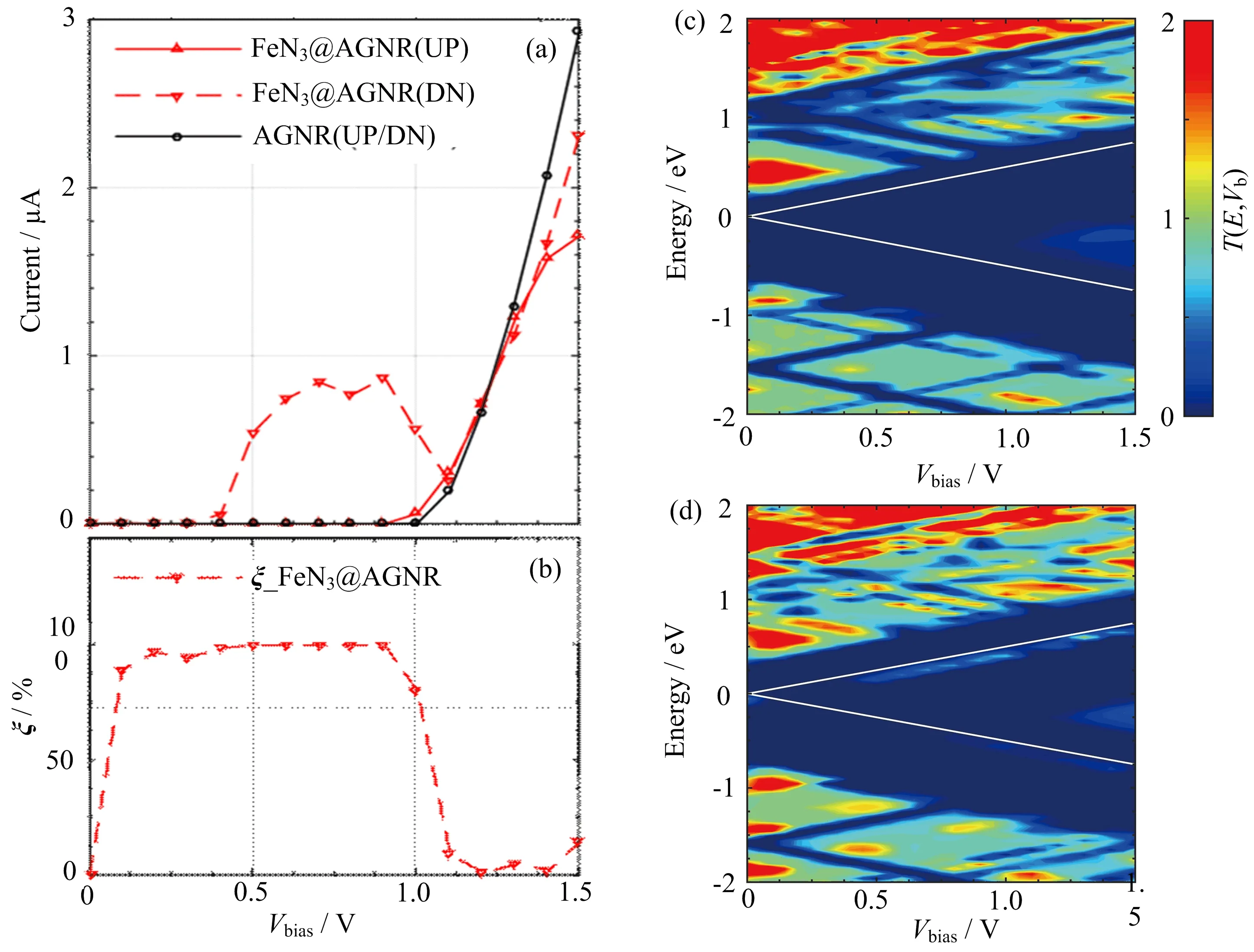
FIG.3 The current-voltage(I-V)characteristics of pristine 13-AGNR,and FeN3@13-AGNR(a),as well as the current polarization(ξ)of FeN3@13-AGNR(b).And the contour of the bias-dependent transmission T(E,Vb)of(c)the spin-up and(d)the spin-down systems of FeN3@13-AGNR.
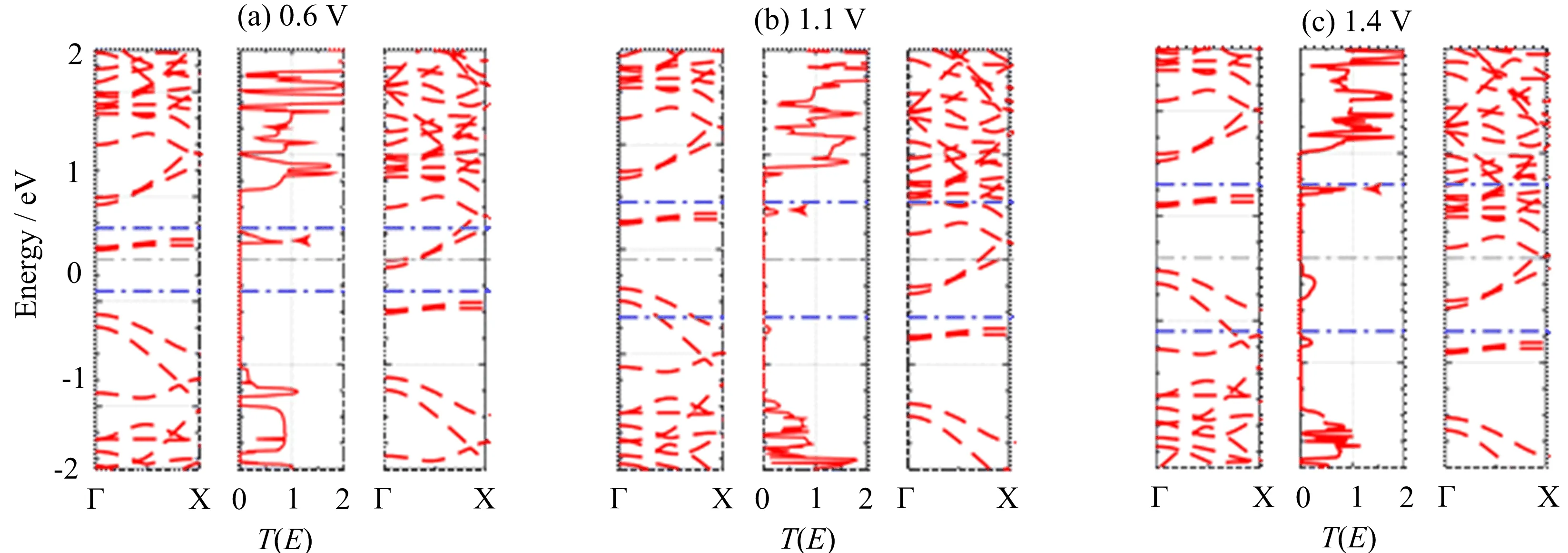
FIG.4 The bias-dependent spin-down band structure of the left electrode(left panels),the spin-down transmission curve(middle panels),and spin-down band structure of the right electrode(right panels)of the spin-down system in FeN3@13-AGNR under bias 0.6,1.1,and 1.4 V,respectively.
To reveal the source of the formed transmission belt,we plotted the band structures of the left and right electrodes,as well as the transmission of spin-down system of FeN3@13-AGNR with Vb=0.6,1.1,and 1.4 V in FIG.4(a),(b),and(c),respectively.One can see a sharp transmission peak appears in the bias window as Vb=0.6 V,due to that there exist overlaps between the VBM of left electrode and the CBM of right electrode.Obviously,the VBM and CBM will still be overlapped as the bias further increases,while the VBM will be overlapped with another CB with a higher energy as Vb=1.1 V,resulting the formation of the transmission belt.As has been noted in FIG.2(c),the VBM of the spin-down system in FeN3@AGNRs is composed of 3d electrons of Fe atom and the 2p electrons of C atoms,while it is not for spin-up system.Hence,it is the FeN3complexes,which have quite diflerent eflects on the spin-up and spin-down systems,giving rise to the striking current-polarization and spin-dependent large NDR behaviors in FeN3@AGNRs.We have also calculated the I-V characteristics of FeN3@ZGNR and plotted the results in FIG.S1(supplementary materials).It shows that both the striking current-polarization and large NDR behaviors observed in FeN3@AGNRs,have not been found in such systems.
IV.CONCLUSION
By applying DFT+NEGF calculations,we have investigated the electronic structure and transport properties of FeN3-embedded GNRs. Strong currentpolarization(nearly 100%)and NDR behaviors have been observed in the FeN3-embedded AGNRs.It is revealed that the FeN3complexes induce quite diflerent eflects on the band structures of the spin-up and spindown systems,resulting in the largely spin-dependent transport behavior and striking current-polarization.Our findings suggest that AGNRs can also be magnetized by embedding of TM atoms and thus have promising applications in spintronics.
Supplementary materials:The calculated spinup and spin-down currents of the FeN3@8-ZGNR are shown in FIG.S1.
V.ACKNOWLEDGEMENTS
This work was supported by the National Natural Science Foundation of China(No.21643011),and the Fundamental Research Foundations for the Central Universities(No.ZYGX2016J067).
[1]K.Parvez,S.Yang,Y.Hernandez,A.Winter,A.Turchanin,X.Feng,and K.Mullen,ACS Nano 6,9541(2012).
[2]S.Li,Y.Hu,Q.Xu,J.Sun,B.Hou,and Y.Zhang,J.Power Sour.213,265(2012).
[3]H.Yin,C.Zhang,F.Liu,and Y.Hou,Adv.Func.Mater.24,2930(2014).
[4]X.Chen and B.Li,Chin.J.Chem.Phys.28,573(2015).
[5]X.F.Li,Q.K.Li,J.Cheng,L.Liu,Q.Yan,Y.Wu,X.H.Zhang,Z.Y.Wang,Q.Qiu,and Y.Luo,J.Am.Chem.Soc.138,8706(2016).
[6]A.K.Geim,Science 324,1530(2009).
[7]O.Cretu,A.V.Krasheninnikov,J.A.Rodr´ıguez-Manzo,L.Sun,R.M.Nieminen,and F.Banhart,Phys.Rev.Lett.105,196102(2010).
[8]Y.C.Lin,P.Y.Teng,P.W.Chiu,and K.Suenaga,Phys.Rev.Lett.115,206803(2015).
[9]K.T.Chan,J.Neaton,and M.L.Cohen,Phys.Rev.B 77,235430(2008).
[10]T.Chen,X.F.Li,L.L.Wang,Q.Li,K.W.Luo,X.H.Zhang,and L.Xu,J.Appl.Phys.115,053707(2014).
[11]L.Jiao,L.Zhang,X.Wang,G.Diankov,and H.Dai,Nature 458,877(2009).
[12]J.I.G.Enriquez and C.V.Al Rey,Inter.J.Hydr.Energy 41,12157(2016).
[13]B.Anasori,M.Beidaghi,and Y.Gogotsi,Mater.Today 17,253(2014).
[14]P.Zhao,Q.H.Wu,D.S.Liu,and G.Chen,J.Chem.Phys.140,044311(2014).
[15]J.Huang,R.Xie,W.Wang,Q.Li,and J.Yang,Nanoscale 8,609(2016).
[16]A.Torres,M.P.Lima,A.Fazzio,and A.J.da Silva,Appl.Phys.Lett.104,072412(2014).
[17]A.Krasheninnikov,P.Lehtinen,A.S.Foster,P.Pyykk¨o,and R.M.Nieminen,Phys.Rev.Lett.102,126807(2009).
[18]H.S.Moon,J.M.Yun,K.H.Kim,S.S.Jang,and S.G.Lee,RSC Adv.6,39587(2016).
[19]F.L.Benedito,T.Petrenko,E.Bill,T.Weyhermller,and K.Wieghardt,Inorg.Chem.48,10913(2009).
[20]J.Du,F.Cheng,S.Wang,T.Zhang,and J.Chen,Sci.Rep.4,4386(2014).
[21]J.Zhang,Z.Wang,and Z.Zhu,J.Electrochem.Soc.162,F1262(2015).
[22]H.Wang,M.Xie,L.Thia,A.Fisher,and X.Wang,J.Phys.Chem.Lett.5,119(2013).
[23]T.Xu,J.Huang,and Q.X.Li,Chin.J.Chem.Phys.27,653(2015).
[24]X.F.Li,K.Y.Lian,L.Liu,Y.Wu,Q.Qiu,J.Jiang,M.Deng,and Y.Luo,Sci.Rep.6,23495(2016).
[25]M.Y.Han,B.¨Ozyilmaz,Y.Zhang,and P.Kim,Phys.Rev.Lett.98,206805(2007).
[26]Y.W.Son,M.L.Cohen,and S.G.Louie,Phys.Rev.Lett.97,216803(2006).
[27]P.Ruffieux,S.Wang,B.Yang,C.S´anchez-S´anchez,J.Liu,T.Dienel,L.Talirz,P.Shinde,C.A.Pignedoli,D.Passerone,T.Dumsla ff,X.Feng,K.Mullen,and R.Fasel,Nature 531,489(2016).
[28]X.Wang,Y.Ouyang,X.Li,H.Wang,J.Guo,and H.Dai,Phys.Rev.Lett.100,206803(2008).
[29]L.Liu,X.F.Li,Q.Yan,Q.K.Li,X.H.Zhang,M.Deng,Q.Qiu,and Y.Luo,Phys.Chem.Chem.Phys.19,44(2017).
[30]W.Lu,H.Chen,S.Liu,J.Zi,and Z.Lin,Phys.Chem.Chem.Phys.18,8561(2016).
[31]A.Kimouche,M.M.Ervasti,R.Drost,S.Halonen,A.Harju,P.M.Joensuu,J.Sainio,and P.Liljeroth,Nat.Commun.6,10177(2015).
[32]F.Xie,Z.Q.Fan,K.Liu,H.Y.Wang,J.H.Yu,and K.Q.Chen,Org.Elec.27,41(2015).
[33]J.M.Soler,E.Artacho,J.D.Gale,A.Garc´ıa,J.Junquera,P.Ordej´on,and D.Sanchez Portal,J.Phys.:Condens.Matter 14,2745(2002).
杂志排行
CHINESE JOURNAL OF CHEMICAL PHYSICS的其它文章
- Imaging HNCO Photodissociation at 201 nm:State-to-State Correlations between CO(X1Σ+)and NH(a1∆)
- Energy-Transfer Processes of Xe(6p[1/2]0,6p[3/2]2,and 6p[5/2]2)Atoms under the Condition of Ultrahigh Pumped Power
- Ultrafast Investigation of Excited-State Dynamics in Trans-4-methoxyazobenzene Studied by Femtosecond Transient Absorption Spectroscopy
- Unexpected Chemistry from the Homogeneous Thermal Decomposition of Acetylene:An ab initio Study
- Direct Observation of Transition Metal Dichalcogenides in Liquid with Scanning Tunneling Microscopy
- Photo-Induced Intermolecular Electron Transfer-Eflect of Acceptor Molecular Structures