An integrated optimization design of a fishing ship hullform at different speeds *
2019-01-05LeiYang杨磊ShengzhongLi李胜忠FengZhao赵峰QijunNi倪其军
Lei Yang(杨磊), Sheng-zhong Li(李胜忠), Feng Zhao(赵峰), Qi-jun Ni(倪其军)
China Ship Scientific Research Center, Wuxi 214082, China
Abstract: This paper shows how to improve the hydrodynamics performance of a ship by solving a shape optimization design problem at different speeds using the simulation-based design (SBD) technique. The SBD technique is implemented by integrating the advanced CFD codes, the global optimization algorithms and the geometry modification methods, which offers a new way for the hullform optimization design and the configuration innovation. The multiple speed integrated optimization for the hullform design is a challenge.In this paper, an example of the technique application for a fishing ship hullform optimization at different speeds is demonstrated. In this optimization process, the free-form deformation method is applied to automatically modify the geometry of the ship, and the multi-objective particle swarm optimization (MOPSO) algorithm is adopted for exploring the design space. Two objective functions,the total resistances at two different speeds (12 kn and 14 kn) are assessed by the RANS solvers. The optimization results show that the decrease of the total resistance is significant after the optimization at the two speeds, with a reduction of 5.0% and 11.2%, respectively.Finally, dedicated experimental validations for the design model and the optimized model are carried out for the computation and the optimization processes. At the two speeds, the reduction of the total resistance in the model scale is about 6.0% and 11.8% after the optimization. It is a valuable result in view of the small modifications allowed and the good initial performances of the original model.The given practical example demonstrates the feasibility and the superiority of the proposed SBD technique for the multiple speed integrated optimization.
Key words: Hullform design optimization, simulation-based design (SBD) techniques, multiple speeds optimization, CFD techniques, total resistance
Introduction
The ship industry has ushered a new era focusing on the energy conservation and the emission reduction,which leads to a new trend of developing green energy saving ships. At the present, the ship design speed is generally based on the shipbuilding contract, namely,the speed in the design draft, which also assures the navigational speed required by the shipyard. Therefore the optimization design of the hullform based on the design speed is reasonable. However, it is not applicable for some ships such as the container ships, the ocean-going fishing vessels, for they may work at different drafts or the load may be varied under the actual operating conditions. Some shipowners have requirements of the speed at several operating points,which will be written into the contract. This fact calls for ship designers to improve the optimization design techniques under different operating conditions according to the ship operation profiles. However, the traditional ship design method (with the design objective of the hydrodynamic performance at the design speed) is obviously difficult to meet the requirements.
With the development of the CFD, the CAD and the optimization theory, a new ship design method/mode, known as the simulation-based design (SBD)technique opens a new way for the hullform optimization design and the configuration innovation[1-2]. In this process, the objective functions (the hydrodynamic performance of a ship) are evaluated by the CFD codes, and the solutions space of the design problem is explored by the optimization algorithm,then the optimized hullform under given constraints is attained at last. The SBD techniques is the most advanced and promising method for the ship hullform optimization design, especially for the complex multi-objective problem, so to speak.
In recent years, the SBD technique was widely utilized for hullform design, with a large amount of literature for the CFD application in the hydrodynamic optimization (mostly for reducing the calm-water resistance and the wave patterns). These studies attest a rapidly growing interest in the hydrodynamic optimization[3-8]. Impressive progress is made by Campana and his colleagues. The key technologies of the SBD including the hull geometry modification and reconstruction, the global optimization algorithms, the parallel computing and the approximation management approach are extensively studied. In a series of papers, Peri et al.[9]investigated a variable-fidelity approach to speed up the optimization process using the free surface RANS in single and multi-objective problems, while Peri and Campana[10]developed a global optimization algorithm, which was applied to the solution of the same test, and carried out experiments to assess the optimization. More recently, Peri et al.[11], Campana et al.[12]reviewed the previous developments of the SBD tool box in dealing with complex design problems.
Diez et al.[13-14]presented a formulation for the multidisciplinary robust design optimization of vessels,subject to uncertain operating conditions. The formulation couples the multidisciplinary design analysis with the Bayesian approach to decision problems involving uncertainty. The numerical shape optimization of a container ship and an LPG carrier was carried out by Han et al.[15]employing the parametric curves generated by the fairness-optimized B-Spline form parameter curves, labeled as the F-Spline. The optimal ship with a completely different bulb shape was successfully validated by the model experiment,showing a 5.7% improvement in the total resistance and a 7.8% improvement in the delivery power. A combined local and global hullform modification approach was developed by Kim et al.[16]and it was integrated into a CFD-based practical hydrodynamic optimization tool. This optimization tool was applied to the hydrodynamic design of the Series-60 hull for reducing the drag at three speeds ( =Fr 0.22, 0.30 and 0.33). An advanced simulation based design tool box based on the high fidelity URANS simulations was tested to optimize a high speed water jet propelled catamaran. These papers witnessed a growing attention on the SBD techniques (CFD-based hullform design) in the ship hydrodynamics design field. This paper describes some algorithms and methods for the numerical optimization of a ship’s calm-water resistance performance for either local or global optimization issues. In the previous studies, almost all the objective functions are the calm-water resistance at the design speed rarely referring to the resistances under different speed conditions according to the ship operation profiles.
This paper firstly introduces the SBD techniques and its key modules, and then illustrates the multiobjective optimization design of a fishing ship at different speeds. In this optimization process, the freeform deformation method is applied to automatically modify the geometry of the ship, and the multiobjective particle swarm optimization (MOPSO)algorithm is adopted to deal with the design space.The resistances at different speeds are assessed by the RANS solvers. Finally, dedicated experimental validations for the design model and the optimized model are carried out for the computations and the optimization processes.
1. Elements and features of SBD techniques
To develop the simulation-based design techniques for the shape design, three main components must be built, which are common among different applications (see Fig.1): (1) an optimization technique for minimizing the objective functions under given constraints, (2) a hull geometry modelling and modification technique for providing a necessary link between the design variables and the deformation of the body shape, (3) a CFD solver as analysis and evaluation tool for regressing the values of the objective function and of functional constraints. The functional components required to support the SBD techniques are briefly analysed and described in what follows.

Fig. 1 SBD-based hullform design optimization environment
1.1 Optimizers
The optimization technique is used to deal with the hullform design space and to obtain the optimal solution. Therefore, the selection of an optimization algorithm to search the optimal solution in the design space quickly and accurately is one of the emphases for the hull optimization design. The global optimization algorithms enjoy several advantages over the local optimization algorithms. They are generally easier to program and parallelize, they do not require continuity of the problem definition, and they are generally better suited for finding a global or nearglobal solution. Accordingly, the global optimization algorithms are recommended for dealing with the practical engineering optimization. In this paper, the MOPSO algorithm is adopted to deal with the multi-speed design problem, which has successful applications in large-scale problems in several engineering disciplines[17-18]. The basic principle of the algorithm and its improvement can be found in Ref. [19].
1.2 Geometry and grid manipulator
An accurate and effective hull geometry modelling and modification technique is essential for the CFD-based hullform design optimization. The flexibility of the geometry modelling and modification technique may have a great impact on the freedom of an optimizer in exploring the design space. Several specific aspects should be taken into consideration.First of all, only a small number of parameters, i.e.,the design variables, are required for the hull geometry variation to minimize the number of objective function evaluations. Secondly, a large variation of hullforms can be obtained to allow for a sufficient free-form design, i.e., to produce different types of hullform. Thirdly, the modified portion can be smoothly integrated to the original design without discontinuities when only one part of the hull needs to be optimized. Finally, the practical hullform can be preserved and various geometrical constraints can be easily implemented in the optimization process. With regard to the grid manipulation, once the hull geometry is modified, the volume grid is adjusted accordingly. In order to avoid the numerical error caused by the meshing format, the grid dimension and the topology structure of the different hulls geometric surface should keep consistent. At present, the FFD approach is suitable for the hull local geometry reconstruction and the integral geometry reconstruction. It was widely used in the ship form optimization design due to its high adaptability[20]. In this paper, the FFD approach is adopted to modify the hull geometry.Some further developments of the FFD are described as well as the original approach in Campana[12].
1.3 CFD solvers
The CFD solvers are the analysis and evaluation tools to regress the values of the objective function and the functional constraints (see Fig. 1). The accuracy of the CFD solvers has a great impact on the practical and optimization process. Generally speaking, the validation and the verification of the CFD solvers should be done in the first place prior to the design optimization. Meanwhile, the improvement gained by the design optimization should be greater than the numerical noise of the CFD solvers. To redesign an existing shape, the precise analysis tools are necessary for guiding the optimizer towards improved solutions. The RANS solvers were widely used by designers for the ship redesign and are the most advanced analysis tools available today. The free-surface RANS code has become a reliable and mature tool in the past 10 years. In the present study,the commercial software FLUENT is used as the CFD solver to carry out a complete RANS simulation for the free-surface flow around a model ship. The validation and verification of the CFD solver, can be found in Refs. [19, 21].
2. Multiple speeds integrated optimization of the fishing ship hullform
The effect of the hullform on the resistance performance is closely related to the speed. Therefore, it is inappropriate for some ships (such as the container ships, the ocean-going fishing vessels) to take the resistance performance at the design speed as the assessment index. On one hand, the optimal hullform obtained for a given speed may not have a consistent resistance reduction in the entire speed range.Contrarily the resistance may increase greatly at other off-design speeds. On the other hand, for some ships,the effect of the hullform transformation on the resistance is closely linked with the ship speed. In different speed ranges, the effect of the same hullform transformation is different, and the difference might even be significant. It is particularly obvious for the mid-high speed ships utilizing a favorable wave interference produced by the bulb to reduce the wave resistance. Thus, the present study focuses on the hydrodynamic optimization for a given speed range,i.e., only to develop optimal hullforms with the minimum total resistance at multiple speeds.
In order to validate the adaptability of the SBD technique in the hullform design at multiple speeds,we choose a 3 000 T fishing ship as the research object for the speed evaluation at two operating points.The main hullform characteristics are shown in Table 1. The side view is shown in Fig. 2.

Fig. 2 The fishing ship side view and hull surface mesh
2.1 Definition of the problem
2.1.1 Objective functions and its evaluation
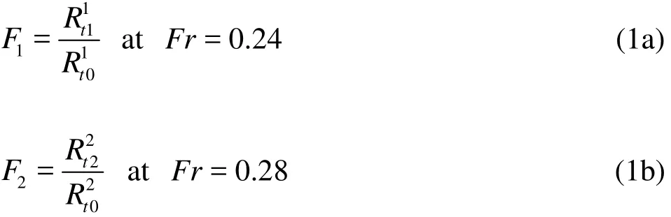
In order to get significant gains for the fishing ship’s total resistance at different speeds, the total resistancesat the speeds 12 knand 14 knare chosen as the objective functions, re-spectively. Two objective functions are defined as follows:

Table 1 Principal dimensions and constraint conditions
The URANS flow solver is used to assess the objective functions. A cell-centered finite-volume method, based on a linear reconstruction scheme that allows the use of computational elements with arbitrary polyhedral topology, is adopted to discretize the governing equations of RANS. The convection terms are discretized using the second order upwind difference scheme. The velocity-pressure coupling is based on the PISO algorithm. The wall function approach is chosen to determine the wall boundary condition of the transport equations for the mean velocity and the turbulence quantities. The shearstress transport (SST) -kω Turbulence model is adopted to calculate the eddy viscosity. The free surface flow is treated as a two-phase flow, i.e., the water and the air, so the volume of fluid (VOF)method is adopted to deal with the two-phase flow.The multi-block structural mesh of H-O type is used in the simulation. The basic principle of meshing is that the grids are congregated in the regions of the bow and the stern of the model, near the hull surface and free surface. The near wall mesh grids are located within the log-law region with averaged+45y≈ (on the order of 820 000 grid points, see Fig. 3). In this paper, for different hull geometric surfaces, the total numbers and the topology structure of grids should be consistent, and the first layer grid dimension of the hull surface should be the same, to avoid the numerical error caused by the meshing format.

Fig. 3 Computation region
2.1.2 Hull geometry reconstruction and constraint conditions
The FFD approach is used for the hull geometry reconstruction in the multi-objective optimization design at two different speeds. The whole hull area is normalized, and then it is put in a cube with 343 control points (see Fig. 4). Twelve groups of control points are chosen as the twelve design variables. In each group, some points are grouped together, as one variable. For a realistic design problem, its geometrical constraints about the bulb length, the buoyancy center, the displacement and the principal dimensions of the ship are imposed on the design variables. The complete definitions of the problem, the objective function and the constraints, are given in Table 1.

Fig. 4 (Color online) Hullform reconstruction by FFD approach
2.1.3 Multi-objective optimization algorithm
In order to search for the hullform bearing potential resistance reduction at two design speeds, it is necessary to employ the multi-objective optimization algorithms. In this study, the MOPSO algorithm is extended to provide a set of optimal solutions by the Pareto front technique.
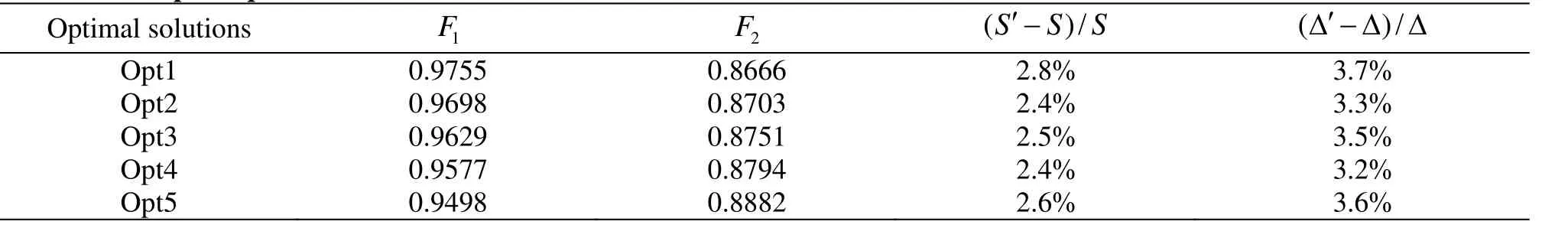
Table 2 The part optimal solution sets and constraint conditions

Table 3 Comparison of resistance components between the original and the optimized
2.2 Design optimization results
In the fishing ship optimization process, the particle population number is 36, and the generation number is 12. The final resulting Pareto front is shown in Fig. 5, where the two objective functions1F andare contradictory. Only five points of the complete Pareto optimal sets of solutions are chosen to compare their resistance performances against the original ones. We select the configurations corresponding to the lowest values of the resistance at speeds 12k n and 14 kn, Opt1 and Opt5, and the points with improvements with respect to all the objective functions, Opt2, Opt3 and Opt4. As shown in Table 2,the second and third columns present the two objective functions, which are non-dimensionalized by its original value. The last two columns show the variations in the wetted surface area and the displacement.

Fig. 5 The Pareto front of the multi-objective optimization problem
In view of the resistance reduction effect, the optimized Opt5 is the most satisfactory one in the five optimized ones. Its total resistance at speeds 12 kn and 14 kn is reduced by 5% and 11.2%, respectively. In this paper, the resistances of the optimized ones at different speedsare numerically simulated by the RANS, and the results are shown in Table 3, Fig. 6. In the potential speed range, the total resistance coefficients are reduced by 7.1%-16.2%, and the higher the speed, the greater the resistance is reduced. And their residual resistance coefficients are decreased by about 25% at different speeds (=0.20-0.32)

Fig. 6 Comparison of the total resistances between the original and the optimized at different speeds

Fig. 7 Comparison of bodyplans between the original and the optimized hullforms
The differences between the optimized and original hull shapes are shown in Fig. 7. At the ship bow close to the waterline, the optimized shapes present a trend of “expansion” as compared to the original, and at the place close to the baseline, the optimized shapes present an obvious trend of “shrink”. The bulbous shape becomes larger significantly. At the ship stern,the optimized shapes present a trend of “shrink” as compared to the original. Figures 8, 9 show a comparison of axial velocity contours at the propeller disk between the original and the optimized. At the propeller disk, the shapes of the non-dimensional axial velocity contours for the original and the optimized are very similar. It shows that the effect of the stern form change on the flow field is very small.

Fig. 8 (Color online) Axial velocity contours at the propeller disk for (right) the original and (left) optimized ship(Fr = 0.24)
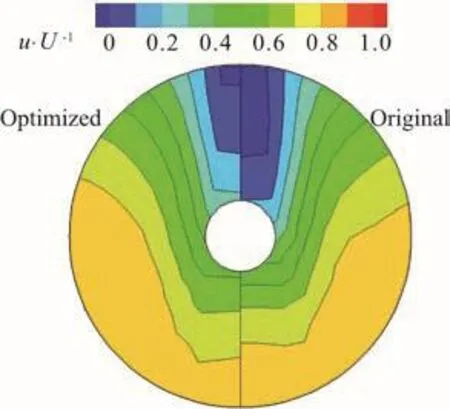
Fig. 9 (Color online) Axial velocity contours at the propeller disk for (right) the original and (left) optimized ship(F r=0.28)
The wave profiles and the wave contours of the original model and the optimized models at two speeds are shown in Fig. 10. The decrease of the bow wave amplitudes of the optimized is significant as compared to the original model. The “wave peak” of the stern for the optimized is less than the original.
The above analyses show the good applicability of the SBD technique in the multi-speed design optimization, and the resistance at different speeds is reduced significantly. The traditional design approaches will be very difficult to achieve these results solely based on the experience of the designers.
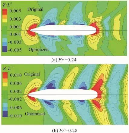
Fig. 10 (Color online) Comparison of wave contours between the original and the optimized
3. Experimental validation
In order to validate the reliability of the optimal design, the resistance model experiments are performed at the CSSRC towing tank with two 4 m (length)models for both the original and optimized hullforms(see Fig. 11). The results of the model experiments are compared in Table 4. The comparison of the CFD and EFD results of the total resistance and residual resistance coefficients between the original and optimized models are shown in Fig. 12. The comparison of the wave form between the original and optimized model is shown in Fig. 13.
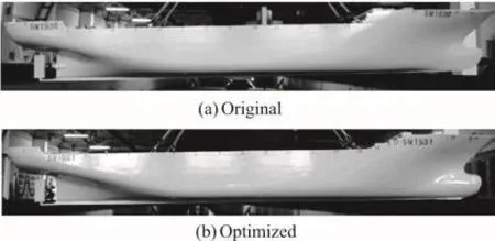
Fig. 11 Experimental models of the original and the optimized
The optimization is proven to be successful by the experimental measurements. The results show that the decrease of the total resistance is significant for the optimized model at different speeds. At the two different speeds (12 kn and 14 kn), the measured reduction of the total resistance in the model scale is about 6.0% and 11.8% for the optimized model,respectively. In addition, it can be seen from Fig. 12 that the CFD results agree very well with the EFD results, which shows high accuracy of the numerical method in the ship resistance optimization.

Fig. 12 Comparison of the CFD and EFD results of total resistance and residual resistance coefficients between the original and the optimized

Fig. 13 Comparison of wave forms between the original and optimized models
The wave form of the original and optimized models at speeds 12 kn and 14 kn is presented in Fig.13. The wave amplitude of the optimized bow and stern is significantly less than the original, which shows a significant improvement for the wave resistance of the optimized model.
4. Conclusions
The multiple speeds integrated optimization for the hullform design is a challenge. In this paper, an example of the technique application for the fishing ship hullform optimization at different speeds is demonstrated. In the procedure, the free-form deformation method is applied to automatically modify the geometry of the ship, and the MOPSO algorithm is adopted for exploring the design space. The objective functions, the total resistances, are assessed by the RANS solvers. The optimization results show that the decrease of the total resistance is significant for the optimization case at two different speeds (12 kn and 14 kn), with a reduction of about 5.0% and 11.2%respectively.
Finally, dedicated experiments for the design model and the optimized model are carried out to validate the computations and the optimization processes.At the two different speeds (12 kn and 14 kn), the reduction of the total resistance in the model scale is about 6.0% and 11.8% for the optimized case. These are valuable results in view of the small modifications allowed and the good initial performances of the original model. The given practical examples indicate the feasibility and the superiority of the proposed SBD technique for the multiple speed integrated optimization problem.
Acknowledgement
The authors would like to thank Liang Yun-fang for the assistances in preparing the manuscript.
猜你喜欢
杂志排行

水动力学研究与进展 B辑的其它文章
- Call For Papers The 3rd International Symposium of Cavitation and Multiphase Flow
- An integral calculation approach for numerical simulation of cavitating flow around a marine propeller behind the ship hull *
- Numerical study on influence of structural vibration on cavitating flow around axisymmetric slender body *
- Critical velocities for local scour around twin piers in tandem *
- Dynamic analysis of wave slamming on plate with elastic support *
- Numerical investigations of the effects of blade shape on the flow characteristics in a stirred dead-end membrane bioreactor *