Inverse Synthetic Aperture Radar Imaging of Multi-TargetsBased on Image Processing Technique
2018-11-28YongWangShuaiFengandQingxiangZhang
Yong Wang, Shuai Feng and Qingxiang Zhang
(Research Institute of Electronic Engineering Technology, Harbin Institute of Technology, Harbin 150001, China)
Abstract: This paper presents a new multi-targets inverse synthetic aperture radar (ISAR) imaging approach via the image segmentation processing. This method can separate multi-targets with similar velocities, and there is no strict limit on the rotational state of the targets. Firstly, the motion compensation for the completely multi-targets echo is carried out and the coarse image can be achieved with the Range-Doppler (RD) technique. Then a series of image processing methods and image segmentation processing are used to separate the echo data of each mono-target. At last, the image with high quality of each target can be achieved with the RD technique and the Range-Instantaneous-Doppler (RID) technique. ISAR imaging results of simulated and measured data validate the validity of the proposed approach.
Keywords: ISAR; multi-targets; image segmentation
1 Introduction
Radar imaging of non-cooperative target has been widely used in military and civil domains for the capacity of all-time and all-weather on the target observation[1-4]. In addition, the ISAR technique is an important part of modern radar signal application because of its 2-D high-resolution ability[5-8]. The range high resolution can be achieved via transmitting the broadband signal, while the high cross-range resolution relies on the target rotation[9]. In the actual application scenario, the target rotation can be obtained via the decomposition of target motion[10]. In addition to the rotation, the rest of the target motion is translation, which induces the range migration and phase error. The method to eliminate the effects of translation is the motion compensation, and accurate motion compensation is the precondition for well-focused imaging[11-12]. In modern radar application scenarios, the situation that multiple targets appear in the same radar beam usually occurs. Due to the diversity of the translation and rotation, the range profiles of different targets can hardly align simultaneously by the traditional mono-target motion compensation method. Many useful method of multi-targets ISAR imaging have been proposed before. The mainstream idea is to separate the signals of the multi-targets and then process the data of each target by the traditional mono-target imaging algorithm[13-14]. Obviously, the key issue is to separate the signals of multi-targets that are mixed together. At present, the main methods are the separation of signals in the time-frequency field, parameter field, or the image field, In terms of time-frequency domain, the methods proposed in Refs.[15-16] separate targets via the Doppler history of different targets. However, the methods are slightly limited because they require the certain distinguishable properties of the different targets acceleration. In terms of parameter separation, the method based on maximum likelihood parameter estimation in Refs.[17-18] considers the complex targets as the simple point targets, and estimates the target motion parameters by maximum likelihood method. Finally, the motion compensation and imaging processing of each target are performed by the estimated parameters. In terms of separation in image domain, the methods proposed in Refs. [19-20] obtain the coarse imaging results of multi-targets, and then the signal of each target can be extracted by image segmentation. However, the assumption of the multi-targets motion is relatively simple. Park[21]focused on the motion compensation of multi-targets before coarse imaging, which achieved good results. However, the image segmentation method is relative cursory. When the targets are adjacent in the 2-D imaging plane, the separation effect is not ideal. The method via the particle swarm optimization (PSO) and CLEAN approach in Ref.[22] can separate the target range profile and obtain the imaging result of each target directly. However, the performance of the method would degrade when the targets possess severe maneuverability or complex three-dimensional oscillation. Generally speaking, the approaches above can achieve effective simulated results under some certain assumptions of the translation and rotation. However, the practicality and effectiveness of the algorithm requires further verification of the measured data.
Here, we present a new technique which can be applied to the situation that all the targets share the analogous translations and different oscillations. This hypothesis is consistent with the motion state of the multi-ship-targets on the sea surface[23]. The proposed method can obtain the coarse imaging of multi-targets based on the traditional mono-target imaging approaches. With the aim being to reduce the background noise and enable the sparse image to be processed by the traditional image segmentation methods, a series of image processing algorithms are implemented, including noise suppression, image interception based on the center of mass, interference fringe suppression, median filtering, and pixel expansion. After the processing in image domain, the signals of each target in the image domain will gather in the independent connected regions, and the image segmentation based on the geometric clustering can be used to extract different targets. Finally, we can use the echo signals of each target to achieve the high-resolution focused imaging results by the traditional mono-target imaging processing, including the RD and RID technique.
2 Imaging Geometry and Signal Model of Multi-Ship-Targets
The geometric model of multi-ship-targets is shown in Fig.1. At the coherent processing interval (CPI), it is assumed that there areQtargets can be observed in the same antenna beam, different targets possess different velocities and three-dimensional oscillations. The blue linesO-UVWrepresent the target observation coordinate system, where the green lines represent the instantaneous radar antenna beam.

Fig.1 Imaging geometry of multi-targets
It is assumed that the targetq,q∈{1,2,...,Q} can be depicted as the summation ofKqscattering points, the instantaneous distance between the scattering pointk,k∈{1,2,...,Kq} of targetqto the radar at instanttisRq,k(t). Generally, the transmitted signal is Linear-Frequency-Modulation (LFM) signal, which can be written as
(1)
(2)
whereσk,qdenotes the backscattering coefficient for the scatteringkin the targetq.
For the special characters of LFM signals, the Dechirping method is used to implement the pulse compression in this paper. The reference distance is assumed to beRref, then the reference signal is written as
(3)
whereTrefis the pulse width for the reference signal, which satisfiesTref>Tp. Then, we can obtain the base band signal by
(4)
Then, the base band signal is shown as
(5)
whereRΔ=Rq,k(t)-Rref. Perform the Fourier transform to Eq.(5), we can get

(6)
Due to the diversity ofRq(t) of different targets, most of the motion compensation method that manifest as the whole move of the range profile, can hardly accomplish the translational compensation of each target simultaneously. This is the essential reason why the traditional mono-target motion compensation method performs poorly in a multi-target imaging situation.
In addition, the ships sailing on sea surface also possess complex oscillations in three-dimensions[24-25]: yaw, pitch and roll, as shown in Fig.1. According to the results in Ref.[26], the three-dimensional oscillation for the ship target can be approximated as the periodic cosine function. The angular velocities in the three directions can be shown as
θl(t)=Alcos(wlt+χl),(l=yaw,pitch,roll)
(7)
whereAlrepresents the maximum angular motion amplitude.wl=2π/Tlrepresents the angular velocity of oscillation whileTldonates cycle of oscillation.χlrepresents the initial angle. Then the three-dimensional oscillation matrix of the target can be expressed as
(8)
Moreover, the synthetic oscillation matrix is shown as
(9)
[Uk(t),Vk(t),Wk(t)]T=Rot(θr(t),θp(t),
(10)
(11)
wherevU(t),vV(t),vW(t) represent the velocities in the three direction of coordinate axisU,V,W, respectively.
As we can see in Eq.(11), due to the time-varying velocity and the three-dimensional oscillation, the rotation of the target could be very complex. In this situation, the classical RD algorithm could cause serious defocus on the azimuth direction[27-28]. As a result, the RID technique is widely used to solve this problem. The most commonly used RID algorithms are based on the LFM signal model[29-35], such as the Wigner-Hough transform, the match Fourier transform, the Dechirp method and the signal decomposition technique. However, if the target has complicated rotational movement, just like the ship model above, the high-order phase term will come into being. In this situation, the RID technique based on the cubic phase signal model will behave better[36-37], such as the PHMT algorithm and the PGCPF algorithm.
3 Processing in Image Domain
The detailed steps of the imaging process are introduced in this section.
(a)Coarse imaging of multi-targets.
For the separation in image domains, the first step in common is to obtain the coarse imaging results. In this paper, the cross-correlation method and constant phase-error elimination method[9]are used to the envelope alignment and phase correction, respectively.
1) Cross-correlation method.
In ISAR imaging, the frequency of pulse repetition is generally high, which makes the envelopes of two adjacent range profiles possess strong correlation. The cross-correlation method calculates the cross-correlation function of the adjacent envelopes and find the peak position, and then utilizes the delay corresponding to the peak to process the envelope alignment. However, due to small error accumulation and single abnormal echo, the traditional cross-correlation method may cause envelope drift and jump error. To avoid this problem, a novel method based on accumulation has been proposed. This method replaces the single echo with the accumulation ofNtime’s echoes, and achieves the optimal alignment in the whole. The cross-correlation function in this method is
(12)
whereei(r) represents the real envelope of theith echo after pulse compression. The jump error can be avoided and the envelope drift can be effectively reduced after appropriate accumulation.
2) Constant phase-error elimination method.
After the envelope alignment, the amplitudes of the echoes are corrected accurately, but the phases are still chaotic. The constant phase-error elimination method is a simplified algorithm to process phase correction for practical engineering applications. Assume the sub-echo envelope of thepth range unit can be simplified as
(13)
whereσ1p(m) andψ1p(m) represent the modulation of amplitude and phase caused by small clutter and noise, respectively.φ1p0represents the initial phase. (4π/λ)mχ1prepresents the phase component due to the Doppler frequency which changes over the slow time .γmrepresents the initial phase error.
Multiply themth echo shown in Eq.(13) with the conjugate of the (m-1)th echo, we can get
(14)
where
Δψ1p(m)=ψ1p(m)-ψ1p(m-1)
andΔγm=γm-γm-1represent the difference between adjacent phase fluctuations and the difference between adjacent initial phase error, respectively. Obviously, the initial phaseφ1p0has been dropped and the Doppler phase has been converted to the constant (4π/λ)χ1p. Then the phase required for correction can be calculated by
(15)
3)RD algorithm for coarse imaging.
After the holistic motion compensation, the range profiles have been aligned roughly. The range profiles can hardly align strictly, because each target has different translational motion. Hence, it is meaningless to use complex accurate imaging method to obtain the coarse image. The RD algorithm is simple, easy to realize by computer and reversible. In addition, due to the complex three-dimensional oscillation of each target, the azimuth direction will create severe defocusing.
In a word, the coarse image obtained by the above method would not focus accurately. However, the signals of different targets will assemble into independent regions. Besides, due to the character of ISAR imaging and complex electromagnetic environment, the pixels in the target area are sparse and the strong background noise will spread throughout the image. The traditional image segmentation methods cannot divide images in this case. A series of image processing methods are used to solve this problem, the specific steps are shown as follows.
(b)Global noise suppression.
The first step of the image processing methods is the global noise suppression. Due to the sea-clutter and the interference scattering points that randomly distribute in the environment, the noise distribution of ISAR image is often complex and random. To suppress the background noise adaptively, this paper propose a novel global noise suppression method by referring to the two-channel CFAR method in the signal detection. The statistical property of the noise is obtained by the elimination of the signal, and the threshold of adaptive detection is calculated by the mean and variance of noise. The detailed steps are:
Step1Compute the meanμ0and varianceδ02of the normalized image, then get the initial thresholdV0=μ0+g0·δ0.
Step2Remove the points with the energy higher than the threshold, and calculate the meanμ0and varianceδ02of the new image.
Step3Calculate the relative errors
whereμiandδi2represent the mean and the variance of the image after theith iteration, respectively.
Step4Terminate the iteration and enter Step 5 whenα<ε1andβ<ε2, otherwise calculate the new threshold byVi=μi+g0·δiand return to Step 2.
Step5Calculate the final threshold asVT=μi+gT·δiand set the value of the pixel in image below that threshold to be zero.
In the above steps,ε1andε2are the default error values, which are set to 0.02 and 0.35 respectively by experience.g0andgTare the threshold factors, which are set to 3 and 3.7 respectively by experience.
(c)Adaptive image intercept.
After the global noise suppression, a large number of useless white backgrounds will appear in the image, these backgrounds will add unnecessary computational burden to the image processing. An effective way to remove the blank background is to intercept the target area. This paper applies a method of adaptive interception based on the calculation of mass center. The specific steps are:
Step1Calculate the zero and first order moment of the image
(16)
whereI(i,j) denotes the pixel intensity ,M×Nis the size of image.
Step2Obtain the coordinate of mass center by the zero order moment and the first moment
(17)
Step3Take the coordinate as the center, and take an image of the sizeK×Kin the original image. In this paper,Kis set to 400.
(d)Fringe and spot noise suppression.
Fringe and spot noise may arise from the strong interference point in the background, or the overlap of the secondary flaps of strong scattering spots. The intensity of these noises is higher than some weak scattering points of the targets, so the global threshold cannot be used to suppress them. Strong spot noise is represented as a small set of pixels in the ISAR image, and the pixel mean of the two-dimensional neighborhood is generally low. Strong stripe noise is generally not continuous in the range unit or the Doppler unit, so the pixel mean in the one-dimensional neighborhood in this direction is weak. In contrast, the scattering points of target tend to be continuous, and the pixel mean in each neighborhood is large. According to the difference, this paper uses the following algorithm to suppress the fringe interference and spot noise:
Step1Set reasonable center pixel thresholdThcand 2-D neighborhood thresholdTh2. The values of two thresholds will directly affect the noise suppression effect, and the thresholds should be increased appropriately when the noise suppression effect is not obvious. In this paper, the thresholdsThcandTh2are set to 0.8 and 0.4 respectively by experience.
Step2Iterate through all the pixels, find the pixels that satisfy
(18)
and setI(i,j) to zero.
After the fringe and spot noise suppression, the edges of the target area are clearer, and the probability of misconnecting between different target areas is also reduced.
(e) Image cavity filling.
After the noise suppression, there are still plenty of holes in the target area. In order to focus the signal of the mono-target scattering points in a connected independent region, these holes need to be filled in.
The main steps of cavity filling are median filtering, pixel expansion, image smoothing, and the binary processing. The median filtering is used to suppress isolated strong scattering points, while protecting the edge and shape of the targets as completely as possible. The pixel expansion is used to fill the holes in the area of targets. The filling effect is directly related to the expansion ratio. The greater the expansion ratio, the better the effect, but too much expansion will connect the different target regions that are originally independent. Therefore, it is very important to choose appropriate expansion ratio. Image smoothing and binary processing can further fill the holes in the target area without undue influence on the outer edge of the target. Since these steps are commonly used in image processing, the detailed principles are not covered in this paper.
(f) Image segmentation.
The image segmentation method based on geometric clustering is used in this paper. The principle of this method is to detect all connected independent regions in the image and then label them consequently. The number of pixels in the connected region determines the order of the label. First, we can select the area of the largest number of pixels to be the region of the target, and set the point outside of the area to be zero. Then, the outline of the selected target area can be obtained. Due to the small expansion radio in the image cavity filling, in the target area there may still exist some holes. The ISAR imaging process shows that the signal of mono-target will gather in a contiguous area in the image domain. The holes can only indicate that the signal energy is low and does not mean that the signals do not exist. To ensure the integrity of the extracted signal, the holes in the target contour should be all filled.
The reasonable filling methods should ensure that the external contour of the target is unchanged, so the image expansion and other algorithms are not applicable here. The endpoint connection method is used to solve the internal cavity problem. The specific steps are:
Step1Go through each row in the image, find the first pixel and the last pixel of the image in each row, and set the pixel values between the two pixels to one. Then the row-connection imageAhas been obtained.
Step2Go through each column in the image, find the first pixel and the last pixel of the image in each column, and set the pixel values between the two pixels to one. Then the column-connection imageBhas been obtained.
Step3Multiply the corresponding pixels ofAandB, and get the composite connection imageC.
This method is similar to the strategy in WeiQi(or go chess). Only the blank areas surrounded by pixel points will be filled, and the blank areas connected to the external blank background will remain unchanged.
4 Imaging Process Based on Image Segmentation
This section will describe the overall process of the proposed methods systematically:
Step1Obtain the range profiles by the pulse compression of the range direction. Then, use the method (a) in Section 3 to get the coarse image of the multi-targets.
Step2Obtain the external contours of the separating targets by using the processing of image domain in (b) to (f) in Section 3.
Step3Extract the separating signals of the targets by the external contours. The extraction method is similar to the band-pass filtering. Set the coordinates of the target area to the passband, and the outer coordinates of the zone are the stopband, the filter in image domain can be obtained. By multiplying the filter and the coarse image, the signals of separating targets can be obtained.
To enable the signals of the selected targets to be extracted as completely as possible, the filter can be expanded before filtering, which is equivalent to amplify the passband slightly.
Step4Return the extracted signals to the data domain and then perform the motion compensation and imaging processing of mono-target. Because of the irregular 3-D oscillation of the ship, the RD algorithm may not be able to get clear imaging results. To solve this problem, a RID imaging method based on PGCPF is used in this paper. The received signals are modeled as cubic phase signals, and the parameters of the signals can be estimated by PGCPF algorithm. The PGCPF ofs(n) is defined in Ref.[37] as:
(-n+m)s*(-n-m)e-jβnm2
(19)
After image processing, we can obtain the RD imaging results and the instantaneous image of each moment.
Fig.2 is the flow diagram for the proposed method.

Fig.2 Flow diagram of multi-targets ISAR imaging
5 ISAR Imaging Results
In this section, the effectiveness of the proposed method are testified by the simulated and measured data.
(a) Simulated data
The carrier frequency of the LFM signal is 5.52 GHz with the bandwidth is 400 MHz. The Pulse Repetition Interval (PRI) is 2.5 ms. The SNR of the received echo is 10 dB. The motional parameters of the targets are shown in Table 1. Fig. 3 shows the simulated target model, and each ship consists of 386 scattering points.

Table 1 Motion parameters of targets
Fig.4 is the normalized coarse image via the method proposed in Section 3. The targets are faintly visible and blurred severely in the azimuth direction. In addition, the influence of environmental noise is obvious in the coarse image. Fig. 5 is the image after the global noise suppression. The background noise has been suppressed well after the processing. At the same time, the target areas are conserved integrally.
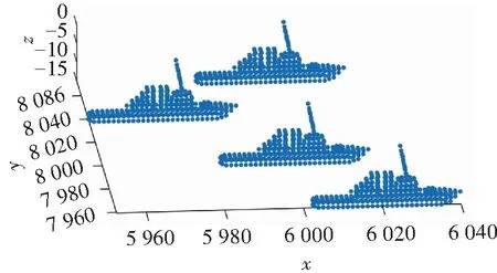
Fig. 3 Simulated target model
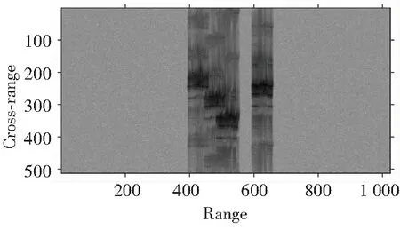
Fig.4 Normalized coarse image

Fig.5 Image after global noise suppression
Fig.6 (a)-(f) are the results of a series of processing in the image domain. Fig. 6(a) is the image after adaptive image intercept, the target area is entirely intercepted. Fig. 6(b) is the image after fringe and spot noise suppression, the isolated strong spot noise and fringe interference are suppressed, and the target is retained perfectly. Fig. 6(c)-(f) are the images after the image cavity filling. Fig. 6(c) is the image after median filtering, the holes in the target area are initially filled while the edge and shape of the targets are protected as completely as possible. Fig. 6(d) is the image after pixel expansion, the holes in the target area are nearly filled, and the areas of different targets still stay independent because of the small expansion ratio. Fig. 6(e) is the image after the image smoothing, the holes in the target areas are further filled without undue influence on the outer edge. Fig. 6(f) is the image after the binary processing, the different targets become independently connected regions. In addition, the boundaries are clear enough to be segmented.
Fig. 7 (a)-(d) show the results of image segmentation based on geometric clustering and endpoint connection. The separating targets are fully extracted, and there are no holes in the target area.

Fig.6 Results of processing in image domain

Fig.7 Results of image segmentation
Fig.8(a)-(d) are the radar images of the Target 1-4 via the RD algorithm. Compared with the coarse image shown in Fig. 4 and the results of processing in image domain shown in Fig. 6, the imaging quality has been greatly improved. This indicates that the important reason for the low quality of ISAR image is the difficulty of accurate motion compensation of each target. Although, the image results can be recognized as a ship, there is still some defocus. In order to estimate the parameters as accurately as possible, this paper considers the multi-component cubic phase signal as the signal model of the echo signals in same range cell. The imaging results in Fig. 9 are obtained by the PGCPF algorithm at selected time positions. Compared with the images in Fig. 8, the defocusing phenomenon no longer appears, and results in Fig. 9 can accurately reflect the external characteristics of the targets.

Fig.8 Radar image via RD algorithm

Fig.9 Radar image via RID algorithm
In order to evaluate quantitatively, the image entropy is used as the numerical evaluation index. The image entropyEn(I) is defined as follows:
(20)
whereI(i,j) denotes the image intensity,M×Nis the size of image. The image entropy of different image results are shown in Table 2. The image entropies of the RD imaging results are much lower than the coarse image, which means the imaging quality has been improved after the target separation and refocusing. In addition, the lowest entropy of the RID image proves the effectiveness of the RID imaging algorithm.

Table 2 The image entropy of different image results
From the processing results of simulation data, the proposed separation method in the image domain is practical and effective, and has certain adaptability. Furthermore, the multi-ship-targets can be accurately focused by the RID imaging algorithm.
(b) Measured data.
To testify the effectiveness of the proposed method in the actual application scenario, a set of measured double-ship ISAR data is selected. The radar works at X band with bandwidth is 400 MHz and the PRI is 2 ms.
Fig.10 is the normalized coarse image of measured data, and the background noise is very complicated. Fig.11 is the image after global noise suppression. Most of the background noise has been suppressed well after the processing except for a small amount of strong spot noise. The results of a series of processing in the image domain before image segmentation are shown in Fig.12.
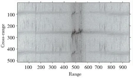
Fig.10 Normalized coarse image
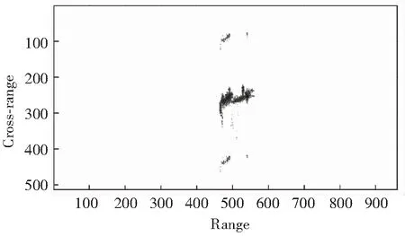
Fig.11 Image after global noise suppression

Fig.12 Results of processing in image domain
Similar to the processing effect of the simulated data, the different targets become independently connected regions and the boundaries are clear enough to be segmented. Fig.13 (a)-(b) shows the results of image segmentation based on geometric clustering and endpoint connection. The main bodies of the separating targets are extracted completely, but there is still a small fractured part of Target 1, which is not recognized as the target.

(a) Target 1 (b) Target 2
Fig.14 (a)-(b) are the imaging results of the targets via the RD algorithm. For the Target 2, the imaging quality is relatively high due to the suitable imaging angle and the small three-dimensional oscillations. In the meantime, the Target 1 is almost unrecognizable because of the poor imaging angle and the serve defocusing phenomenon in the azimuth direction. Fig.15(a)-(b) are the imaging results by the PGCPF algorithm at selected time positions. For Target 2, the image quality is slightly improved. As for Target 1, due to the bad imaging angle of Target 2, no suitable instantaneous imaging instance can be found in the CPI. The image entropy of different image results are shown in Table 3. By the entropy value, we can obtain the conclusion which is same as the visual judgment.

(a) Target 1 (b) Target 2
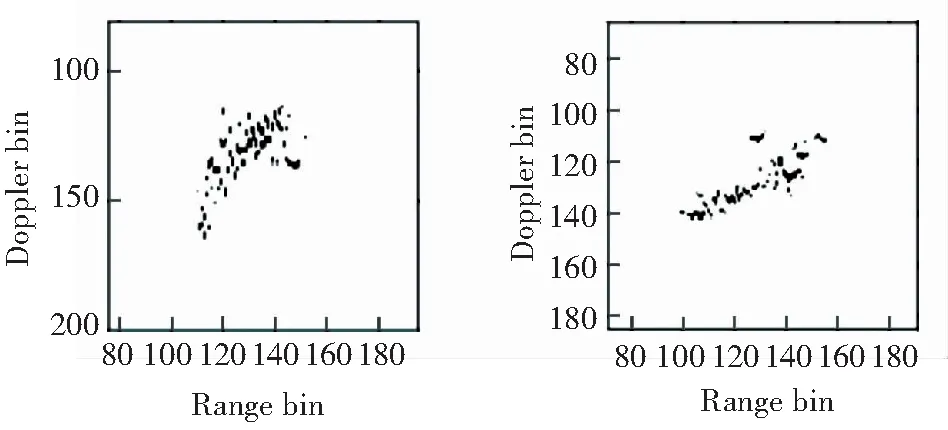
(a) Target 1 (b) Target 2
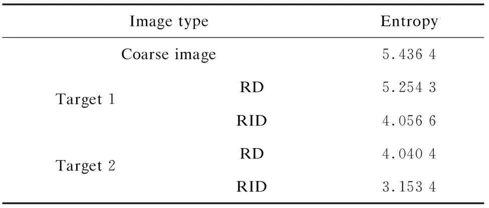
Table 3 The image entropy of different image results
6 Conclusions
A novel method for multi-targets ISAR imaging based on image segmentation is proposed in this paper. This method can be applied to multi-targets ISAR imaging with similar motion. After coarse imaging, processing in the image domain, image segmentation and the target extraction, the signal of each target can be obtained. Then, the well-focused radar image can be obtained by utilizing the imaging algorithm of mono-target. The ISAR imaging results of the simulated and measured data have testified the effectiveness of the proposed method. Nevertheless, the proposed method relies on the quality of coarse image. When the image quality of the coarse image is poor, for example, the azimuth exists a large number of false targets; the performance of the algorithm will be poor. This issue is the focus of future research.
杂志排行

Journal of Harbin Institute of Technology(New Series)的其它文章
- Review:A Survey of Single Gimbal Control Moment Gyroscope forAgile Spacecraft Attitude Control
- Dynamics Analysis of Square Unit and its Combined Mechanismwith Joint Clearance
- Experimental Study on Shear Behavior of New-TypeSteel-Concrete Composite Bridge Deck
- Review:A Critical Assessment on the Predictability of 14Micromechanics Models for the Stiffness and Strength ofUD Composites
- Theoretic Diffraction Research on the Order-Disorder Effect ofTransition Metal in Li(Ni1/3Co1/3Mn1/3)O2
- Three-Dimensional Normal Stress for Controlling Electronic Structureand Magnetic Property of Fe2Ge