Review:A Survey of Single Gimbal Control Moment Gyroscope forAgile Spacecraft Attitude Control
2018-11-28YunhuaWuFengHanBingHuaZhimingChenDafuXuandLinlinGe
Yunhua Wu, Feng Han, Bing Hua, Zhiming Chen, Dafu Xu and Linlin Ge
(1.School of Astronautics, Nanjing University of Aeronautics and Astronautics, Nanjing 210016, China;2.Aerospace System Engineering Shanghai, Shanghai 201108, China)
Abstract: Agile attitude maneuver is a basic requirement for next generation imaging spacecraft and Control Moment Gyroscope (CMG) is an effective candidate for large space station and agile spacecraft attitude control because of its torque amplification capability. This paper provides a thorough survey of Single Gimbal Control Moment Gyroscope (SGCMG) in terms of configuration, evaluation, modeling, singularity analysis and steering logic,etc. For specific space missions, CMGs are logically mounted into different particular arrays which can be chosen by the proposed evaluation methods. From the dynamic model we find a tough inverse mapping problem which suffers the inherent geometric singularity. Different techniques and theories then are applied for singularity analysis and CMG steering logics design.The pyramid CMG cluster and singular robust logics are proven to be able to enhance the agility of spacecraft. Above work forms a systematic framework of SGCMG for agile spacecraft control with lots of illustrative examples, tables and figures, and will evoke further investigation for future missions.
Keywords: agile spacecraft;SGCMG; CMG configuration; singularity and steering logic
1 Introduction
Control Moment Gyroscope is a kind of spacecraft attitude control actuator[1-2]. It has the absolute advantage of powerful torque amplification capacity over Reaction Wheel (RW), thruster, magnetic torquer, etc.CMG, owing to its efficiency, plays a significant role in large spacecraft attitude control[2-7]. Besides, large-angle maneuver, multi-target acquisition and pointing of agile satellite also rely on great output torque of CMG.Both Skylab and Salyut Space Station employed CMG system, and the International Space Station (ISS) took benefit on double gimbal control moment gyroscope[8-9].The World View series satellites launched by the Digital Globe and Ball Aerospace and Technology Corporation could capture High Resolution (HR) images for their agility. World View 4 (Fig.1,launched in 2016/11/11) is the most advanced agile satellite and World View 1 (Fig.2,launched in 2001) is the first commercial HR satellite actuated by CMG[10]. Table 1 illustrates some properties of Pléiades-HR imaging satellites, Pléiades-1 and Pléiades-2[11-13].What we can find is that their rapid maneuver capability is beyond tradition satellites′. Tiangong 1 and Tiangong 2 were also equipped with several single gimbal control moment gyros.
Bong Wie[14]predicted that the future space mission would have a slew rate requirement of 6 °/s for the next generation earth observation and imaging satellite to get HR image. It is obvious that CMG would draw the attention of researchers in the future[8, 15].
Generally, CMGs are mounted into particular group, known as CMG configuration,with a certain number and structure according to different task requirements[16-17].The configuration varies to satisfy different conditions. The pyramid configuration, more practically, with four CMGs mounted as a rectangular pyramid for 3-axis control is the mini-redundant group. Most scientific theoretical studies and practical experiments adopt this configuration due to its functional integrity,theoretic maturity and structural simplicity and symmetry. Other configurations with more than 4 CMG units or less than 3 units (non-redundant configuration) are also studied.
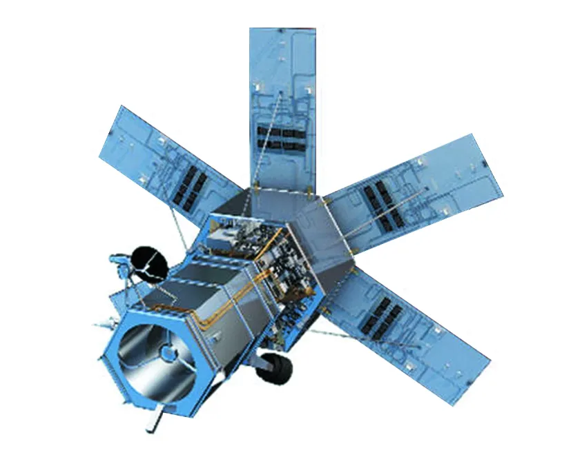
Fig.1 World View 4 satellite

Fig.2 World View 1 satellite

Table 1 Pléiades-HR imaging satellite property
The most serious situation, however,in using CMG is the inherent geometric singularity problem in which there is no torque output in particular direction,meaning an uncontrollable sate[4, 8, 16].Based on the consideration above, it urges investigators to make clear and distinguish the singularity problem and steer CMG with an excellent performance somehow. Theories and strategies change and vary for CMG singularity analysis. Different approaches can give a unique insight into singularity description and depiction. Meanwhile corresponding CMG steering logic/law would emerge consequently. Some new modern methods, rather than the classical techniques like Null Motion[3, 6, 18-21]and Singularity Value Decomposition (SVD)[22-23], are employed to CMG such as game theory[24]and differential geometry[19,21,25]. All of those techniques and strategies establish the comprehensive CMG theoretical framework.
Many literatures are studied to setup an integrated system for SGCMG in this work and their core ideas are reorganized by certain principles. The rest of this paper is briefly outlined as follows. In Section 2, different CMG configurations are presented after the discussion of CMG fundamentals, as well as the CMG configuration evaluation methods. Section 3 summarizes four different CMG modeling methods, examined by some CMG clusters in Section 2. Section 4 presents the visualization tools to form and depict the intuitional impression of the CMG singular moment surface. Based on this surface, different approaches are used for singularity analysis. In Section 5, different CMG steering logics/laws are compared and analyzed in terms of their errors and singularity escaping ability. Section 6 summarizes the entire work with some proposals for future research.
2 CMG Configuration
This section will focus on the configuration and evaluation of CMG, while some fundamentals will also be presented to provide comprehensive and systematic CMG basic knowledge for CMG dynamic modeling in next section.
2.1 CMG Fundamentals
Active attitude control actuators of modern spacecraft can be categorized into 3 main groups, including moment exchanging actuator, mass expulsion actuator and environment interactive actuator.Thruster categorized into the 2nd type depends on propellant or fuel consumption to generate control torque. However, propellant can not be replenished on orbit. In spite of considerable torque, the short-term operating life prevents its implementation in agile spacecraft. The magnetic torquer and reaction wheel,the representative of the 3rd and 1st type respectively,are energy-efficient without the requirement of chemical propellant consumption, making they can work in long-term space missions. However,their output torque is relatively small and does not meet the spacecraft rapid maneuver requirements,even without consideration of reaction wheel dead zone and saturation problems[15].
While the CMG,especially the SGCMG, a kind of moment exchanging actuator, performs well to improve the agility of spacecraft.Although the singularity is serious and intractable, it can be escaped by certain logics.
A CMG consists of 3 main parts as presented in Fig.3.
1)A Flywheel which holds on a constant angular momentum magnitude;
2)A Gimbal which supports the flywheel;
3)A Gimbal Motor which changes the gimbal direction (the direction of flywheel momentum) to generate the desired torque according to the control torque command.
CMG tracks the control signal by exchanging the momentum with the spacecraft, the same way as RW.What distinguishes CMG and RW is the way of momentum changing, direction or magnitude.

Fig.3 Single gimbal control moment gyroscope
According to the mechanical characteristics, CMG can be characterized into 3 types as presented in Fig.4.
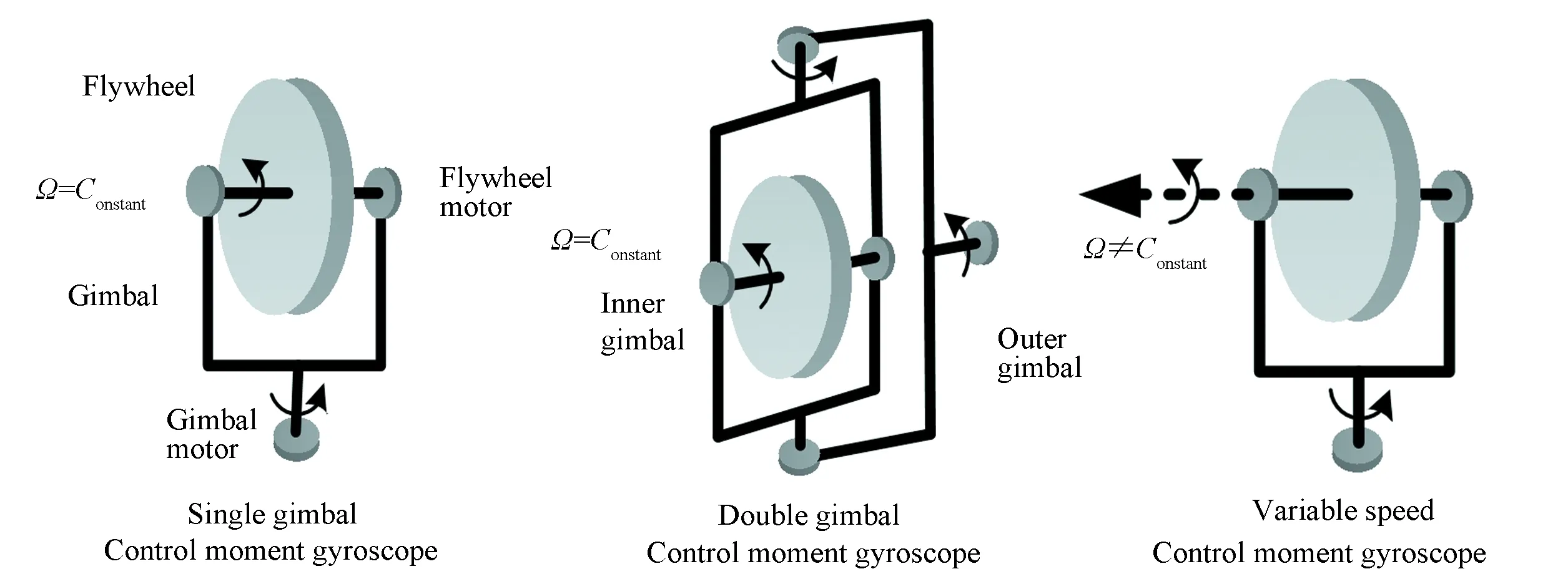
Fig.4 Different types of control moment gyroscope
1)Single Gimbal Control Moment Gyroscope, only one degree of freedom (DOF)exists for momentum direction.
2)Double Gimbal Control Moment Gyroscope, (DGCMG), two gimbals (inner and outer)are mounted so that the output torque would be generated for two DOFs.
3)Variable Speed Control Moment Gyroscope, (VSCMG), both the magnitude and direction of flywheel momentum vector could bechanged.
It is extremely clear that DGCMG and VSCMG have 2 DOFs, with thus more mechanical and dynamical complexity.SGCMG has been studied more frequently and comprehensively because of the structural simplicity, light mass and in particular the powerful output capacity. In following text, unless otherwise mentioned, CMG refers to SGCMG.
The CMG operation mechanism is illustrated in Eq.(1):
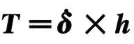
(1)
2.2 CMG Configuration
To achieve 2-axis or 3-axis attitude maneuver and stabilization control of spacecraft, CMGs should be mounted into specific arrays or configurations.
Three-axis attitude control requires at least 3 CMGs. When taking system reliability into consideration,we could find only redundant arrays are practicable. The same concern will be involved in this paper and more texts will be occupied by redundant CMG. That does not mean we will pay no attention to non-redundant arrays,since the redundant clusters is the extension and expansions of non-redundant arrays.
2.2.1Non-redundantCMGconfiguration
The choice of redundant or non-redundant configurationis are determined by specific space requirements and the cost. Most agile imaging satellites, such as the earth observing satellite, only have a large torque requirement along the roll and pitch axes. So the advisable strategy is to employ 2 or 3 CMGs with the parallel gimbal axis for roll and pitch axes control, while RW can be mounted to track the yaw axis command with a relatively smaller torque[21].
Fig.5 shows a 3-parallel CMG system, where the gimbal axes are parallel. It can generate 2 dimensional output torque lying in a plane perpendicular to the gimbal axis. Once the flywheel momentum direction of each CMG changes as commanded, the system will generate the desired torque.
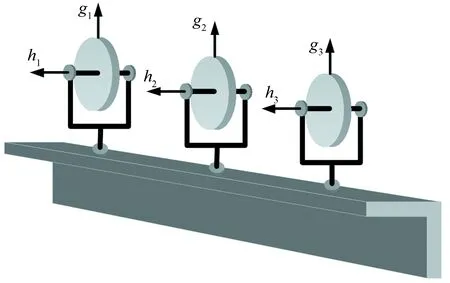
Fig.5 3-Parallel configuration CMG cluster
2.2.2RedundantCMGconfiguration
In general cases, large-angle maneuver, multi-target acquisition and reorientation are basic capacities of modern spacecraft. Obviously, non-redundant system may not be qualified for this kind of full axis maneuver missions[16-17].This requires some special and appropriate CMG clusters,especially the redundant clusters. We can not deny that some redundant CMG systems are upgrades of non-redundant arrays.
Most CMG researchers focus on the pyramid configuration(the min-redundant cluster). The regular pyramid is the main type,while other specific ones for the need of theoretical research are summarized as well, though they may never sever in any orbiting spacecraft.
A) Pyramid configuration.
Pyramid configuration, as a representative of redundant type, also known as rectangular pyramid has been studied from the 1960s[26-29], which has a min-redundancy of one. In other words there are 4 CMGs, as illustrated in Fig.6.

Fig.6 Pyramid configuration CMG cluster
Fig.6 depicts the pyramid or rectangular pyramid configuration, in which there are 4 SGCMG units mounted in an orthogonal relationship along theXandYaxis of Spacecraft Reference Frame(SRF).The four gimbal axes are normal to the pyramid side surfaces,respectively. And the angleβdenotes the skew angle. Skew angleβvaries in different cases,53.13°, 54.73° and 60° are most common values.The Pléiades-HR satellites have employed pyramid cluster as attitude control actuator to get HR images.
It’s obvious that pyramid configuration is symmetrical. Once unexpected disturbances acts on one CMG, the other 3 can track control command through reconstitution without loss of full axes control ability because of the redundancy.
Crenshaw[30]argued a special case of pyramid configuration (as illustrated in Fig.7),β=90 °, named Two-Scisored-Pair-Ensemble,Explicit-Distribution,2-SPEED. The gimbal axes lie along the SRFXandYaxes, resulting into two orthogonal pairs of two parallel CMG arrays.
B)Tetrahedron configuration.
In Ref.[9], tetrahedron mount CMG clusters is given and is compared with the classical pyramid CMG array, as shown in Fig.8.
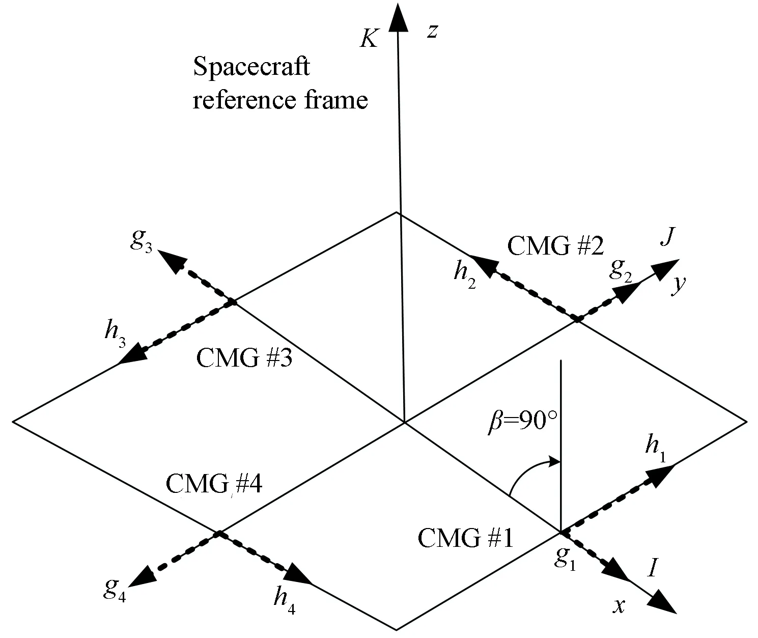
Fig.7 2-SPEED cluster

Fig.8 Tetrahedron configuration CMG cluster
The tetrahedron configuration, like the pyramid clusters, is a redundant 4-CMGs system. In this configuration, each gimbal axis is perpendicular to one surface of the tetrahedron. In Fig.8, we may find that 4 CMGs shape like a methane. Each CMG is equivalent to each other in three dimensional space in terms of structure and function. Analysis implies that the momentum envelope of this configuration is much larger than the pyramid cluster’s[9], owing to the symmetry. A larger momentum envelope indicates larger momentum storage capability.
C) 5-CMGs configuration.
Apart from the 4-CMGs arrays, various 5/6-CMGs[4-5, 9]serve as a great part in theoretical and practical research.There is no doubt that the Five Pyramid Configuration (FPC)is the main role of 5-CMGs system expanded from pyramid cluster. Mounting a CMG with its gimbal axis lying along theZaxis of SRF in a pyramid cluster, we would get another 5-CMGs system (named as‘Pyramid-Z’ configuration). Fig.9 and Fig.10 represent the two clusters respectively.

Fig.9 Five pyramid configuration CMG cluster
The FPC shares similar properties, such as redundancy and mounting symmetry,with the pyramid configuration.

Fig.10 Pyramid-Z configuration CMG cluster
D) 6-CMGs configuration.
Inspired by extension of 4-CMGs system, one can derive some specific 6-CMGs configuration from 5-CMGs cluster. Definitely, hexagonal pyramid cannot be ignored.And, the FPC-Z configuration(with one CMG added in the FPC whose gimbal axis is parallel to theZaxis of the SRF)is the main part.
Other non-redundant arrays such as 2/3 parallel clusters can inspire us to obtain several very unique configurations. By adding 2 CMGs in the SPEED cluster with their gimbal axes parallel to theZaxis of SRF, we can obtain the cube configuration[9], as shown in Fig.11.

Fig.11 Cube configuration CMG cluster
Double 3-parallel cluster, another example of the improvement of non-redundant arrays, can also serve as full axes control actuator[4-5], shown in Fig.12.
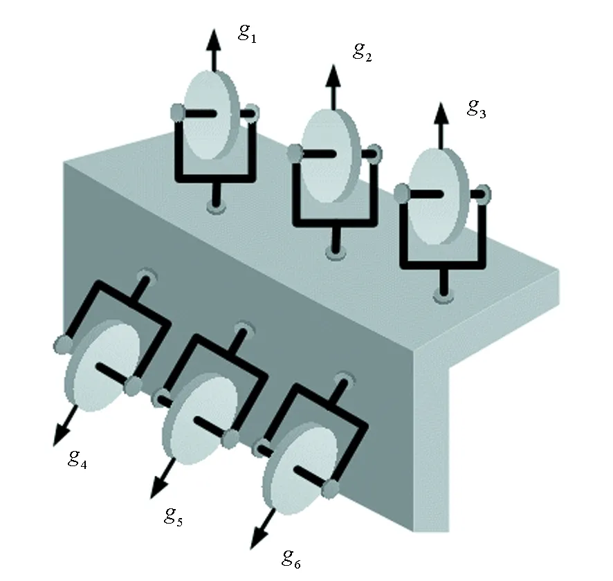
Fig.12 Double 3-parallel configuration CMG cluster
Although one can argue that there are some More-Than-6-CMGs, more redundancy means more complexity in control algorithm and steering logic,larger payload and cost, which may counteract the agility of the spacecraft.The sphere configuration with infinite CMGs whose gimbal axes lie along the radius vector direction acquires greatest redundancy.
2.3 Evaluation of CMG Configuration
The CMG configuration efficiency and evaluation are essential for designing and evaluating an optimal configuration for a specific space mission.The evaluation system consists of static and dynamic indexes.The static indexes are determined by the configuration, while dynamic indexes characterize the performance of CMG cluster in mission phase. Configuration efficiency, controllable efficiency and failure efficiency are the three traditional static indexes[31-33]. However, the configuration efficiency is not normalized, and the controllable efficiency depends on the magnitude of the angular momentum envelope.The normalized indexes, capacity ratio and no-singular ratio,were proposed as a supplement[32].
2.3.1Staticindex
In this subsection we will discuss the static index without consideration of the CMG dynamic performance.All those evaluation criteria could help setup or select a kind of cluster for specific space mission.
A)Configuration efficiency.
Configuration efficiency denotes the ratio of the minimum momentum of the CMG cluster’s momentum envelope or the radius of the inscribed sphere of the momentum envelope over the sum of angular momentum of each CMG, and is described as:
(2)

A greaterγindicates larger space of system angular momentum and output torque for control.
B) Controllable efficiency.
The controllable efficiency refers to the ratio of the inscribed sphere of the nearest elliptic singular point (which cannot be treated by null motion) within the system angular momentum envelope over the sum of angular momentum of each CMG, and is described as:
(3)
whereδESis the elliptic singular gimbal angle set.
The controllable efficiency describes the maximum ideal CMG momentum motion space without any significant singular points, in which the singularity can be avoided through basic null motion to achieve high efficiency for CMG steering.
C) Failure efficiency.
It is hard to guarantee the reliability of each CMG in the cluster during the entire lifespan.The failure efficiency is the configuration efficiency of the new configuration with failure of one CMG.
(4)
where,the superscript (*) denotes the corresponding quantities in failure situation.
D) Singular loss ratio.
The difference between the configuration efficiency and the controllable efficiency is defined as the singular loss ratio, and is written as:
Δ=γ-χ
(5)
It characterizes the area where elliptic singular points appear intensively and restricts the non-singular motion of CMG. A lagerΔspace raises greater challenge for CMG control.
E)Capacity ratio and no-singular ratio.
Using normalized method, Ref.[26] introduced other two static indexes.
Capacity ratio:
(6)
No-singular ratio:
(7)
where,γmax=π/4 corresponds to the sphere CMG configuration. Both capacity ratio and no-singular ratio are relative indexes and are more general.
2.3.2Dynamicindex
The dynamic index refers to a measurement describing how singular the system is or how far the cluster will be in singularity[29]. And it is given by:
ξ=det(JTJ)
(8)
where,J∈R3×nis the Jacobian Matrix of the system withnCMGs.The index becomes zero only when the cluster encounters singularity. The index naturally is regarded as the measurement or ruler to describe the current state of CMG system.
2.4 Summary of Configuration
For different space mission requirements, researchers have studied various CMG clusters, among which no one can meet all control situation.So, it’s significant to understand the unique characteristics of all the clusters.The advisable way is to make use of the evaluation method to choose the optimal array for specific requirements. Of all the clusters the pyramid cluster and FPC-Z cluster are most outstanding, in terms of the redundancy and efficiency. The future 3-axis scientific exploration should fully exploit these two arrays.Fig.13 illustrates the relationship of extension, expansion and evolution among all the clusters, in which the same line style represents that the corresponding CMG configurations have similar characteristics.
The efficiency of traditional configurations is summarized in Table 2.
As shown in Table 2, we can find that pyramid configurations (including the pyramid-Z cluster) have a lager configuration efficiency value meaning that these clusters have larger envelope for momentum movement in some degree.For the cube cluster,γ=χ, which implies that there is no internal elliptic singular point in the momentum and is a best case for CMG control. However, its failure efficiency is the least among 6-CMGs system as illustrated in Table 2, which means the reliability of the cube cluster is low. And the FPC-Z cluster system has the largest configuration efficiency as well as other indexes over the others.That’s the reason why both Tiangong-1 and MIR space station adopted this kind of configuration.In general, the pyramid and FPC-Z clusters are two effective candidates for 3-axis control of agile spacecraft.

Table 2 Efficiency and evaluation for different CMG configurations

Fig.13 CMG configuration relationship
3 CMG Dynamic Modeling
The dynamic and mathematical model of the CMG cluster will be treated in this section. Several different CMG modeling methods are introduced for some unique CMG arrays.These methods or techniques will be examined by CMG clusters in Section 2.
3.1 CMG Model
The so called dynamic model is used to determine the mathematical relationship between the input and output of a system.The gimbal rate and momentum or torque are two main quantities in CMG, corresponding to input and output respectively. In this paper the angular momentum of the gimbal frame is neglected, as the gimbal rate is much less than the speed of flywheel.
Hereafter, four modeling methods, including coordinate transformation method, configuration method, generalized constrain model and inverse kinematic model, will be introduced.
3.1.1Coordinatetransformationmethod
According to the relationship in Eq.(1) and the mechanical constraint (the orthogonality between gimbal axis and momentum of flywheel), a Gimbal Coordinate Frame (GCF)emerges logically, as illustrated in Fig.3, where the {g,h,f} just lies along the unit vector {ig,jg,kg}.
Considering a cluster consists ofnCMGs, there always exists a set of Euler Angles {φi,θi,ψi} to transfer current state ofith CMG state from its GCF to SRF,i=1,...,n. The Direction Cosine Matrix (DCM) for this transformation is as follows:
(9)
where,Ci=R(φi)R(θi)R(ψi), and {I,J,K} is the orthogonal unit vector of SRF.
Eq.(9) implies that all the quantities can be represented in SRF with certain transformation. And we have:
(10)
where,hgiis the angular momentum vector of theith CMG represented in its GCF, and has constant magnitude. The torque equation can be generated by applying differentiation to Eq.(10) or by vector sum of each CMG torque (Eq.(1)).
(11)
or
(12)
Note that the two equations above are the same actually. This method has the benefits of universality and simplicity and its key is to determine the Euler angles in Eq.(9).
3.1.2Configurationmethod
In Ref.[9], the author introduced a novel modeling method for tetrahedron CMG cluster. First the system momentum is represented as:
Hcmg=h0(Asinδ+Bcosδ)E
(13)
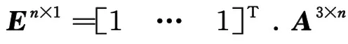
(14)
Consequently the torque in SRF is written as:
(15)
J=Acosδ-Bsinδ
(16)
Eqs.(13) and (15) imply how the configuration influence the dynamic model, as the name configuration method suggests.
3.1.3Generalizedconstrainmodel
To avoid the computation of Jacobian matrix inversion, which is a tough and complicated problem, Refs.[4-5] introduced generalized constrain model to expand the dimension of the Jacobian matrix by adding constrain conditions. A Jacobian matrix ofnCMGs cluster belongs toR3×n, so there should bem=n-3 constrains
(17)
then
(18)

The constrains should guarantee non-singularity, that’s:
(19)
The key is to find constrains, which would really relieve the burden on inversion calculation and singularity avoidance.
3.1.4Inversekinematicmodel
Contrary to the models above, the inverse kinematic model is bullied for singular avoidance by calculating the gimbal angle rather than gimbal rate in Ref.[28].
Supposing one gimbal angle of pyramid cluster is decided, the procedure adopts the dichotomy and newton iteration method to search the other three angles with the requirement of singularity avoidance. Using this logic, the author proposed Inverse Kinematics Computational Procedure (IKCP) and Inverse Kinematics Steering Logic (IKSL) and discussed optimized program for online control. The simulation and ground experiment showed that IKSL was capable of real-time implementation although there existed eighth-order polynomial equations.
3.2 Example of CMG Cluster Modeling
In this part, above modeling methods will be examined by several classical configurations, as illustrative examples.
3.2.1Modelingforparallelcluster
Although non-redundant CMG arrays are not qualified for three-axis control, they can still serve in Earth observing and imaging tasks, as mentioned in Section 1. With the gimbal axes parallel to each other (supposinggi=Kshown in Fig.4), 2 parallel cluster’s dynamic formula is
(20)
and the control torque is
(21)
which is quite simple due to its configuration.
3.2.2Pyramidclustermodeling
As the major CMG configuration, pyramid cluster (not only refers to rectangular pyramid)has been widely used and deeply studied. It is shown that the coordinate transformation method can suit all symmetric clusters, especially for the pyramid arrays or their variants.
By observing Fig.3, theith CMG gimbal axis ofn-pyramid array can transform to SRF by a set of Euler angles with the sequence 'XYZ' as follows:
Ri=[-δi,π/2-β,2π(i-1)/n]
(22)
where,βis the skew angle. The direction cosine matrix (DCM) is
Ci=Angle2Dcm(Ri,'XYZ')
(23)
where,Angle2Dcmrepresents the transformation function from Euler angle to DCM with 'XYZ' sequence.
Consequently the momentum equation of pyramid cluster is

(24)
wherehiandhgiareith CMG momentum in SRF and GCF respectively.Ci-xydenotes (x,y) element ofith DCM matrix.
The system output torque then is
(25)
We supposeh0=1 without losing of generality.The momentum and torque equations of pyramid cluster (PC)with 4 CMGs matrix form are
(26)
and
(27)
where,ci=cosδi,si=sinδi, cβ=cosβand sβ=sinβ.
3.2.3Tetrahedronclustermodeling
Applying the configuration method to tetrahedron cluster, we can get the configuration matrixes:
(28)
then the Jacobian Matrix can be derived by using Eq.(29)
J=Acosδ-Bsinδ
(29)
3.2.4Cubeclustermodeling
By adding three independent constrains below,the cube cluster’s dynamics formula can be written as the generalized constrain model.
δ1-δ2=0,δ3-δ4=0,δ5-δ6=0
(30)
and the constrain equation is

(31)
The constraints implying the CMGs mounted alongX,YorZaxis have the same magnitude of gimbal rate respectively in SRF[4].The generalized constrain model is illustrated by Eq.(33).
The dynamic index is
det(JE)=-8cos(δ1)cos(δ3)cos(δ5)
(32)
which implies that the singular point isδ1,δ3,δ5=±π/2 and that’s the saturation point where the momentum reaches the edge of envelope and is a trivia state. In other words, there are no internal singular points forJE. The detailed analysis can be found in Refs.[4] and [5].
(33)
3.3 Summary of CMG Modeling
Four different CMG modeling methods are introduced and examined by particular cluster. Exactly speaking, the former two are modeling methods while the latter two are special model types.The coordinate transformation modeling method has the absolute convenience especially when dealing with all kinds of pyramid and symmetric configurations.We advise that the generalized constrain model should be further studied to find the general constraint form for different clusters.Thus CMG singularity can be more easily handled.
4 CMG Singularity Analysis
The significant challenge in CMG application is the inherent geometric singularity where the cluster is failed to track the command signal[4, 8, 16]. The steering logics designed to avoid/escape this situation involve comprehensive knowledge and theory. Null motion[3, 6, 18-21]generates zero net torque but helps increase the rank of Jacobian matrix at singular state.Focusing on CMG singular momentum surface structure,differential geometry and topology deal with manifold to distinguish singular problem. Singular value decomposition[22-23]can give a new insight into the Jocabian matrix,while inverse kinematics[28]focuses on the singular gimbal angles. The thorough singularity analysis is the first step for CMG steering and this section thus presents a diverse series of methods for singularity description.
4.1 Singularity Mechanism
At first we would like to introduce the singularity concept or mechanism(how and why CMG cluster fall into singularity).
Definition1:The CMG cluster (whose gimbals are not parallel to each other) traps into singularity if and only if all units’ outputfilie in a plane which the command vectorτis normal to, for some specific gimbal angel setsδs=(δ1,…,δn), represented in Fig.14. Consequently the vector which is perpendicular to the torque plane is named as singular vector and the corresponding gimbal angel sets are called singular gimbal angles.
The definition implies degeneration of torque space to 2-dimension and this is the explanations why CMG fails to operate. All CMGs can be singular but SGCMG suffers most severely[32].
Considering a cluster arranged withnCMGs:
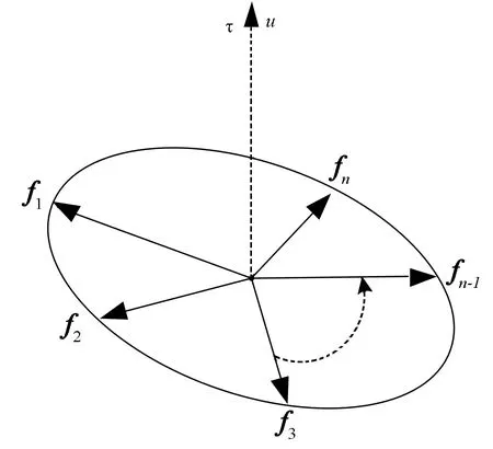
Fig.14 Singular torque
(34)
where
(35)
Note thatfiis theith column vector of the Jacobian matrix. And when the cluster is in singularity, we have:
fi·u=0 orJTu=0 ,i=1,…,n
(36)
Eq.(36)known as singular condition implies:
rank(J)=2<3
(37)
which meansJis no longer full rank or det(JJT)=0, posing a tough problem for CMG control.
4.2 Singularity Classification
The dynamic function indicates the 1-to-1 orn-to-1 mapping from gimbal angle space to momentum space, which inversely may not be so simple. There are more gimbal angle solutions for given momentum and some angles could reduce the rank of Jacobian matrix and encounter a singularity unexpectedly.
Therefore, CMG singularity can be categorized into two types, elliptic singularity and hyperbolic singularity[21, 34]. The following analysis would demonstrate that the former is more severe.
4.2.1Ellipticsingularity
Once CMG moves into elliptic singularity, no other substitutable angle sets exist with a full rank Jacobian matrix, which in other words poses the 1-to-1 mapping relationship between gimbal rates and torque output.
The elliptic singularity, in terms of the singular momentum magnitude, has two parts, saturation/external or internal. As the name suggests the so-called saturation or external singular momentum reaches the maximum or edge of momentum envelope along the singular vector direction. It can no longer generate output torque (by increasing the size), the only path is the tangent of the envelope. On the contrary internal momentum is less than saturation value.
4.2.2Hyperbolicsingularity
The hyperbolic singularity emerges when another solution exists for the given momentum. Those angles can be traversed using null motion, with no effect on momentum. Hyperbolic singularity has two subsections degenerate and non-degenerate. The Jacobin matrix is full rank when in a non-degenerate singularity.
4.3 Singularity Evaluation
The momentum of CMG is a continuous function parameterized by gimbal angles, which means the cluster enters into singularity gradually. It is suggested that some active strategies should be carried out when in the neighborhood of singularity.
So the principal step is to evaluate or measure how far the cluster reaches the singularity. Some steering logics based on this idea have been designed. The frequently-used evaluation functions are summed up blow.


3)S3=min(1/|di|), wherediis theith row vector ofJT(JJT)-1;
4)S4=min(σi), whereσiis the singular value ofJ[23,25];
5)S5=cond(J), wherecondis the condition number function[36];
The functionS1is widely used due to its simplicity and correspondence to singular sate, in whichS1=0 and rank(J)=2. The smallerS1becomes, the worse CMG cluster state is.
An advisable strategy is to apply a different law when measurement function value passes through the threshold rather than when CMG encounters the singularity.These functions on other hand can examine the performance of steering law.
4.4 Singularity Visualization
Note that all the singularity evaluation functions are scalar functions whose value cannot reflect the singularity mechanism and geometric characteristics. Different configurations have different kind of singularities and even for a specific cluster it can be singular at different gimbal angle combinations.
It is urgent to depict the singular momentum surface that represents the geometric properties and describes the relationship between singularity and configurations. Hereafter, some classical ways are introduced to depict the physical graphs and refine the understanding of CMG singularity, known as singularity visualization.
4.4.1Singularityvisualizingmethod
Singularity visualizing methods can be categorized into three main parts, global search[36], Margulies-Auburn method[37]and the technique based on inverse kinematic model[28].
A) Global search.
The CMG would be singular along any direction in 3-dimensional space. We can consequently search all the singular momentum in a specific direction, and then extend to the whole space thoroughly[36]. The procedure is demonstrated below.
1) Set the singular vector which would travel around the space, for exampleu=cosθcosφI+cosθsinφJ+sinθK, whereθandφare the latitude and longitude angle.
2) Search the singular angle for the given direction.
3) Calculate the momentum and identify the type of the singularity.
4) Move the singular vector and take the above steps until all singularities are found.
5) Depict the momentum.
The program above is clear and simple, but it is a tedious process.
B) Margulies-Auburn method.
The singular vector was also employed by Margulies-Auburn[37]to search the momentum. What however makes the difference is that no gimbal angle will be needed to execute the procedure.
Theith CMG outputfiis norm to singular vectoruand there exists the orthogonal relationship among {gi,hi,fi}. In other words,fiis perpendicular to bothgiandu, and we consequently have:
(38)
Considering {gi,hi,fi} is a set of unit basis vector set, we have:
hi=fi×gi
(39)
Substituting Eq.(38) into Eq.(39) we obtain:
(40)
whereεi=±1 andgi≠u.
So the singular momentum of the CMG system is:
(41)
whereHs=Hs(u)=Hs(θ,φ). The momentum is parameterized by two variables rather thannvariables in Eq.(26). There are 2ncombinations of {εi} for ann-CMGs cluster, which can reduces to 2n-1due to symmetry(for example, all positive {εi} and all negative {εi} share the same momentum).
In Ref.[28], the author proposed the visualizing technique based on inverse kinematic model, which can give the local momentum surface while Margulies-Auburn method cannot.
4.4.2Exampleofsingularityvisualizing
The Margulies-Auburn method in this part will be examined by several CMG clusters. Meanwhile the geometric properties will be analyzed.
A) Parallel configuration.

{εi}=〈{+,+,+},{+,+,-}〉
(42)
which corresponds to saturation and internal singularity or 3H and 1H singularity, as illustrated in Fig.15. There simply are two concentric circlesR=1,3 respectively.

Fig.15 Singular momentum line of 3-parallel clusters
B) Pyramid configuration.
The surface of pyramid cluster is much more complex. It is three-dimensional unlike the circular line of the parallel arrays.
The gimbal vectors represented in SRF are:
(43)
where, the skew angleβ=54.73°.There are eight combinations for (εi), corresponding to three different kinds of singularity 4H, 2H and 0H, illustrated in Table 3. Fig.16 depicts the singular surface of pyramid cluster.

Table 3 Singularity type of pyramid cluster
Fig.16(a), (c) and (e)show the 4H, 2H, 0H singular surface, respectively.Due to structural symmetry, the surfaces also appear symmetric.Fig.16 (b) shows the largest momentum is about 3.3 rather than 4 as the name 4H suggests.What is more the largest momentum in different direction varies. Eight holes resulted from the conditiongi≠uexist on the 4H surface (Fig.16(a)) which can match the trumpet-shaped surface in 2H (Fig.16(c)) smoothly and form whole momentum envelop, as illustrated in Fig.16 (f).(In order to show the structure of the envelope, there is only half of 4H surface.)
C) Cube configuration.
More complexity comes along with more units in CMG cluster. The cube configuration with 6 CMGs would show some new findings about the singularity surface. The gimbal axis vectors are:
(44)
Definitely,there should be 6H, 4H, 2H and 0H surface. The visualization is shown in Fig.17.
Besides the similar properties with pyramid cluster, there is something unique and interesting. The projections of Fig.17(a) in three different direction show that the 6H surface resembles a cube with edge length of 8 and circles (radius=2) on the surface. 4H surface is a combination of three same ellipsoids which are the same as the saturation surface of 2-SPEED configuration. The same circles can also be found on 2H and 0H surfaces. All singularity surfaces can be put together and are illustrated in Fig.18.
Fig.18 depicts the multi-layers of cube cluster singular momentum surface, which means more energy will be consumed to pass through those layers from inner one to outer one. All 0H and 2H surfaces make up the first layer, 4H is the second layer,6H together with 2H trumpet-shaped surface forms the third layer. Both the first and second layers are internal,while the third one is external, known as momentum envelop.

Fig.16 Singularity Visualization of pyramid CMG cluster
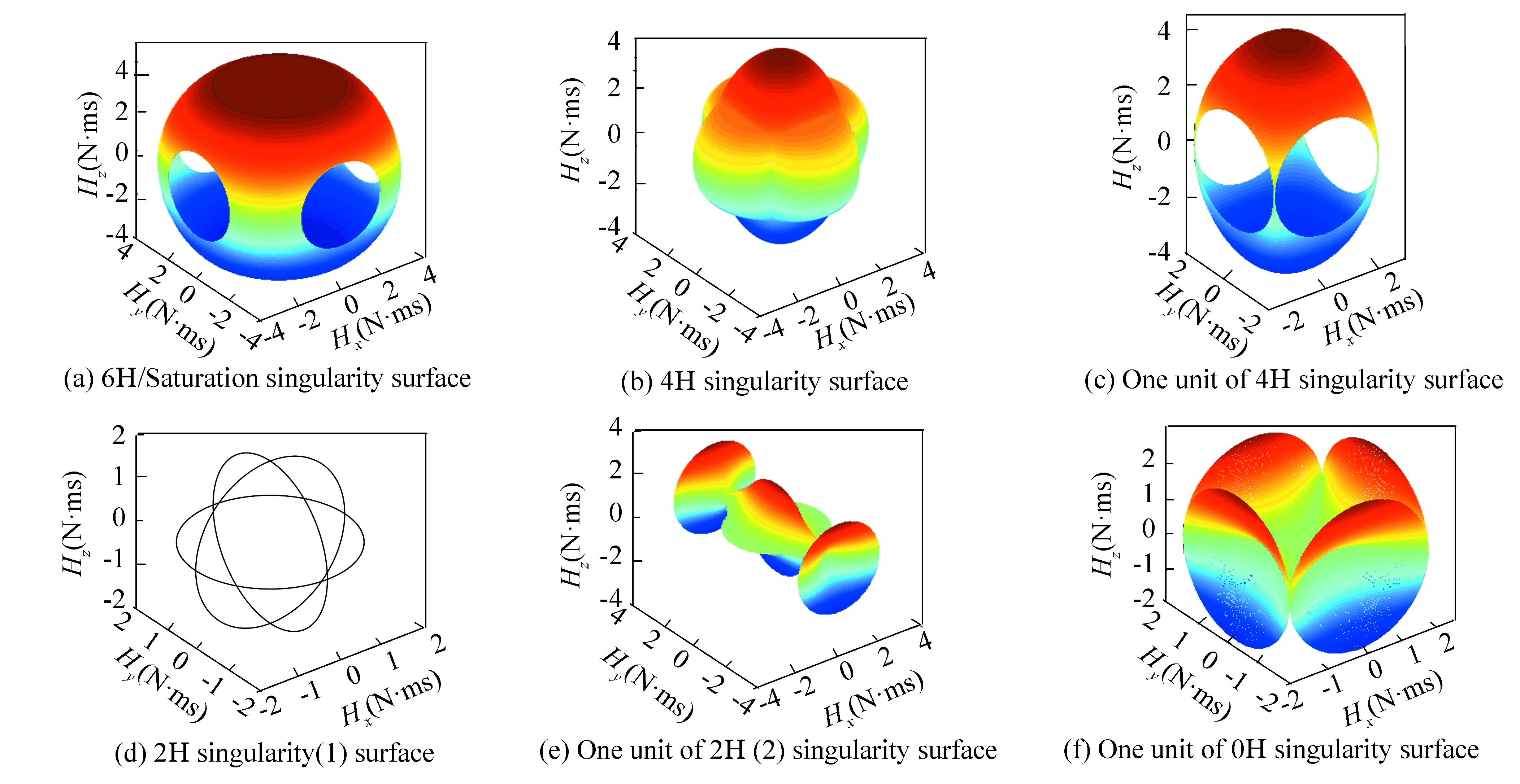
Fig.17 Singularity Visualization of cube CMG cluster
4.5 Binet-Cauchy Identity
The Margulies-Auburn method above simplifies the visualization problem by reducing the variables to 2 but gives no concern about the gimbal angle. In some cases, however, we should know where the CMG could be singular to plan gimbal angle path. Here a new mathematical method,Binet-Cauchy Identity[38],will help to analyze the gimbal angle.
The evaluation functionS1, when in singular sate implies:
det(JJT)=0
(45)

Fig.18 Singular surface of cube cluster
Applying Binet-Cauchy identity to the above equation:
(46)
where,Mi=det(Ji) andJiis the matrix withith column vector removed from the Jacobian matrix. Using Eq.(46), the singular condition of pyramid configuration can be rewritten as:
Mi=sβ[(si+1si+2ci+3+ci+1si+2si+3)+
cβ(ci+1ci+2si+3-si+1ci+2ci+3)+
2(cβ)2ci+1ci+2ci+3]=0
(47)
where,i=1,2,3,4.(Note that the subscript of each quantity in Eq.(47)cannot be larger than 4, otherwise it should subtract 4).
Eq.(47) implies that there are four conditions when in singularity. Dominguez and Wie[39]argued that only two conditions were independent because the minimum rank of Jacobian matrix was 2. Consequently we can figure out the singular angle set.
Whenci≡cosδi≠0, four conditions can be simplified as:
tanδi+2(tanδi+1+tanδi+3)+cβ(tanδi+3-tanδi+1)=-2(cβ)2
(48)
Using any two of the above 4 equations (in Eq.(48)), one may get the angle solutions.
Case 1: For allδ1,δ2, we get:
δ3=tan-1[(-2(cβ)2-tanδ1(tanδ2-cβ))/
(tanδ2+cβ)]
δ4=tan-1[(-2(cβ)2-tanδ2(tanδ1+cβ))/
(tanδ1-cβ)]
(49)
The other five cases (whenci≡cosδi≠0) and cases whenci≡cosδi=0 can be found by the same way.Corresponding singular surface can be defined by Eq.(26).
The graphs for all six cases (ci≡cosδi=0) are demonstrated in Fig.19(a). And meanwhile we put momentum surface and Fig.19(a) together (Figs.19(b)-(f)). There are 6 kinds of color corresponding to 6 cases. Eight bigger ellipses (red and black line) in the projection figure (Figs.19(b), (c)) determine the basic frame of CMG momentum roughly. What is more all lines just like skeleton support the surface which resembles covers.
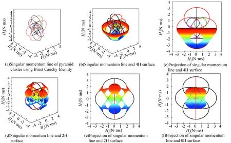
Fig.19 Singularity Visualization of pyramid cluster using Binet-Cauchy Identity
4.6 Null Motion
Allfiare coplanar in singularity, and then the CMGs lose 3-axis control capacity. The hyperbolic singularity can be escaped by null motion as discussed above[3, 6, 18-21], while elliptic singularity cannot. The motion that generates zero net torque is named as null motion, its mathematical form is
(50)
The changes of momentum (torque) for null motion represented in SRF is
(51)

(52)
given dhi/dδi=fiand d2hi/dδi2=-hi, then:
(53)
Considering only first-order term:
(54)
Taking inner product of Eq.(36) with singular vector and applying the singular condition (54), we obtain:

(55)
whereei=uThi.
Considering only second-order term:
(56)
which can be rewritten as matrix form:
(57)
where,E=diag(ei).

4.7 Singular Value Decomposition
In this part a new mathematical method, singular value decomposition, will be employed to analyze the characteristic of Jacobian matrix[22-23]. For a cluster consists ofnCMGs, there exists orthonormal matrixesUandVsatisfying:
J=USVT
(58)
where
andUUT=I3,VVT=InAndSrepresents block matrix with the following form:

(59)
whereσ1>σ2>σ3is the singular value ofJ. So:
(60)
And the singular index is rewritten as:
(61)
When the CMG system traps into singularity, rank(J)=2 andσ3=0. What’s moreu3is the singular vector (JTu3=0) and the null motion space is
(62)
Consequently the null motion gimbal rate is
(63)
where,ciis scalar parameter denoting the magnitude of null motion gimbal rate.
Above analysis indicates that the singular valueσ3denotes the singular degree of CMG system. Both singular vector and null motion space can be decided by SVD. Moreover,the SVD method will be further used in steering logic design.
4.8 Differential Geometry
The discussion above provided several classical methods for singularity analysis, which in some degrees still cannot identify CMG geometric characteristics. Some new viewpoints can be found by using differential geometry[19, 21, 25, 40], and the key conclusions about the CMG singularity are summarized here.
The three dimensional unit vector parameterized byθ1,θ2is given by:
u=uxI+uyJ+uzK=sinθ2I-sinθ1cosθ2J+cosθ1cosθ2K
(64)
and we can defineu1andu2as:
(65)
SimilarlyH1andH2for given singular momentumHs(θ1,θ2) are
(66)
wherei=1,2. Then we have:
G=[Gij]=[Hi·Hj]
B=[Bij]=[-Hi·uj]
C=[Cij]=[ui·uj]
Given following mapping:
(67)
consequently we have:

(68)
therefore,D=G-1B=BG-1, and furtherC=DGDT=DB=G-1B2=B2G-1.
In the same way we assume:
(69)
Then the first fundamental form of singular surface would be diagonalized as:
I≡dH·dH=dθTGdθ=ωTETBEω=
ωTIω=ω12+ω22
(70)
And the 2nd and 3rd fundamental forms are:
(71)

(72)
wherek1,k2are the eigenvalues ofLand tr is to find the trace of a matrix. The relationship among them is

(73)
Equivalently we have:

(74)
The sign of Gaussian curvature suggests an elliptic point ifk>0, hyperbolic point ifk<0 and parabolic point or planar umbilic of the surface ifk=0 for specificH*[21].
4.9 Summary of Singularity Analysis
In this section, CMG singularity are analyzed and visualized by several classical and modern methods.Singular surface presents intuitive expression about CMG singularity, which can be evaluated and measured by certain functions. We analyzed the gimbal angels, null motion and the properties of Jacobian matrix from different angles of view.Different methods for singularity analysis would inspire some unique steering logics. The next section would concentrate on steering laws.
5 CMG Steering Strategy
The major concern for using CMG as spacecraft attitude control actuator is steering strategy design. On one hand it is expected to solve the inverse mapping problem, and on the other hand the accuracy should be guaranteed. What is more the CMG inherent geometric singularity is the main problem which deserve more attention. The pseudo-inverse solution is considered as an exact method without any torque error but fails to escape singularity. In order to escape the singularity null motion[3, 6]is added to the pseudo-inverse solution, which however can only deal with the hyperbolic singularity.When making a compromise between the accuracy and robust, researchers have proposed the singularity robust steering logic[8, 10], of which the generalized singular robust logic is most effective with singularity escape for all singularities. To minimize the torque error further, the singular direction steering logic[22-23]has been derived by the SVD method.Besides these, other techniques[1, 18-21]and theory are also applied to CMG control.This section will summarize different steering logics and finally form a comprehensive and integrated CMG theory framework.
5.1 Overview of CMG Steering Strategy


(75)
The definition above implies:1)the torque command must be tracked precisely within error tolerance; 2)the system should be controllable which means singularity avoidance.
Many researchers have proposed various logics although the above requirements sometimes could not be guaranteed exactly.
5.2 Pseudo-inverse Steering Logic

(76)
whose solution is expected to minimize the index:
(77)
Consequently the pseudo-inverse solution is the mini-two norm solution[8,10,20].More generally, let’s discuss the weighted minimum-two norm problem:
(78)
whereQ=QTis a weighted matrix.
The Lagrange multiplier method will be used to find the solution and the Lagrange equation of this problem is
(79)
whereλis Lagrange multiplier. The partial derivative ofLfor the optimal problem should meet:
(80)
(81)
from Eq.(80) we have:
(82)
substituting Eq.(82) into Eq.(81):
(83)
So
λ=[J(Q-1)TJT]-1τ
(84)
substituting Eq.(84) into Eq.(80):
(85)
consideringQ=QTwe have:
(86)
5.3 Null Motion Steering Strategy
The null motion is added into steering logic to deal with the singular problem[3, 6, 30-31, 35]. The algebra implies the integrated form of solution for an equation contains: the particular solution and homogeneous solution. So gimbal rate for Eq.(76) is
(87)
(88)
Another way to determine the null motion vector is
n=(I-J+J)d
(89)
wheredis a nonzero vector and is usually chosen as:
d=gradf=
(90)
where
(91)
Above method is the gradient method[3]. Null motion however still fails to deal with elliptic singularity. Consequently Ref.[41] proposed the approach of state feedback along with null motion. Choosing Lyapunov energy function as:
(92)
whereδris the reference sate. The performance index is
(93)
The achieved solution is:
(94)
The first term is pseudo-inverse solution and the second is null motion solution. Eq.(94) in ideal conditions can avoid singularity.
5.4 Steering Strategy with Torque Error
In large-angle attitude maneuver scenarios, the extreme accuracy will not be a major concern, which implies much tolerance for torque error. Some singularity avoidance/escape logics[3,8,10, 21]introduces torque error to treat the singular problem.
By adding some error into mini-two norm problem, we can find:
(95)
(96)
where:
J#1=[JTPJ+Q]-1JTP=Q-1JT[JQ-1JT+
P-1]-1=WJT[JWJT+V]-1
(97)
whereW=Q-1,V=P-1.[JTPJ+Q]-1∈Rn×nand [JWJT+V]-1∈R3×3are always non-singular because of the positive definiteness of matrixQandP. Generally weighted matrices are chosen as:
(98)
(99)
OnceP=0 it will become pseudo-inverse logic. And whenQ=λI4, we can get the generalized singular robust steering logic:
J#2=[JTPJ+λI4]-1JTP=JT[PJJT+λI3]-1P=JT[JJT+λP-1]-1=JT[JJT+λE]-1
(100)
where:
(101)
Further,whenP=I3andQ=λI4, it will degenerate to the singular robust steering logic:
J# 3=[JTJ+λI4]-1JT=JT[JJT+λI3]-1
(102)
The parametersλ,∈iandWiabove should be properly chosen.Parameterλdecides whether it will introduce error or not. Ifλ=0, we can get the precise solution. Therefore an advisable way is to set a threshold value (Eq.(103)) to add the torque error:
(103)
whereS=[det (JJT)]1/2andS0is the threshold.Another continuous function[9, 30, 32]is
λ=λ0exp[-μdet(JJT)]
(104)
where,λ0andμare scalar parameters. The worse CMGs system is, the lagerλbecomes and consequently the more errors are added.
For any non-zero torque command, generalized singular robust steering logicis should guarantee non-zero gimbal rate solution. The simple way is to modulate ∈icontinuously:
∈i=∈0sin(ωt+φi)
(105)
where,the amplitude ∈0, frequencyωand initial phaseφishould be properly selected.
The singular robust steering logicJ#3cannot guarantee the singularity escape and even can constrain the available momentum workspace. The sensor noise would result in singularity when usingJ#3[3,8,21].J# 2could deal with all internal singularities and exploit the momentum envelope fully.WhenW≠I,J#1is expected to escape all kinds of singularities including the saturation singularity with a compromise between accuracy and robustness.
5.5 Singular Value Decomposition Analysis for Steering Logic
Here the singular value decomposition will be used again to find some interesting factors of the logics discussed above.Pseudo-inverse steering logic can be decomposed as:
J+=VS+UT
(106)
where:
(107)
So
(108)
and whenσ3=0,it’s advised:
(109)
similarly we have the form forJ#3=VS#3UT, where:
S#3=
(110)
SVD implies the orthogonality between {u1,u2,u3}, which can construct a set of three-dimensional basis unit vector. And torque commandτrepresented by this new basis can be rewritten as:
(111)
Substituting Eq.(111) into Pseudo-inverse logic:

(112)
The output torque is:

(113)
and the torque error is
(114)
similarly the gimbal rate solution forJ#3is

(115)
The control torque is:

(116)
and the torque error becomes:
(117)
We can find the torque error inJ#3is as designed.
Here we may have a more deeply understanding about the matrixesUandV. The gimbal rate is a linear combination ofvi(i=1,2,3 when CMG cluster does not encounter singularity). What is moreUis the torque space and the singular valueσiplays an important role in the mapping between torque and gimbal rate. Once the system is singular,σ3=0 and the output torque space degenerates to 2-dimension expressed byu1andu2.Meanwhilev3degenerates to null motion solution andu3becomes singular vector.
5.6 Singular Direction Steering Strategy
Singular value decomposition implies torque error in some logics. In order to reduce error further, singular direction avoidance is proposed[22-23]. It is:
(118)
where:
(119)
And torque error is
(120)
when in singularityΔτSDA=τ3u3,which means no torque along the singular direction and is terrible situation. The modified singular direction avoidance successfully handled the singularity is proposed by Tao Meng[23]with an Euler rotation to {u1,u2,u3}.
SVD inspired people to complement the error along the singular direction by making use of hybrid actuators. The strategy argued by Jin Lei[42]is a good example and the CMG steering logic is
(121)
(122)
where,λis determined by Eq.(104). The control law for momentum wheel is
(123)
5.7 Generalized Inverse Steering Logic
Based on generalized-inverse, Ref.[26] proposed steering law for pyramid CMG system (four CMGs in this configuration). Pseudo-inverse and singular robust are said to suffer internal singularity and cannot exploit the entire workspace. The generalized inverse law would solve this tough problem.
Defining a new set of anglesψ∈R3and a mapping, we have:
ψ=g(δ)
(124)
Considering a new matrixA(δ)
(125)
and so
(126)
For a non-singular matrixJAT
(127)
Consequently
(128)
The matrixA(δ) is chosen asA=J+H, in which the column vectors ofJare orthogonal to the column vectors of matrixH. Simulation results indicate the accuracy in attitude maneuvers and singularity avoidance. The great momentum capacity of CMG is fully exploited to track the command torque.Moreover, the proposed steering logic brings gimbal angle to zero at the end of maneuver serving as an initial condition for next time.
5.8 Generalized Constrained Steering Strategy
The generalized constrain model is designed to move the burden from steering logic designing to modeling. Now let’s focus on a simple cluster of 3-parallel with following Jacobian Matrix
(129)
The constrained condition[4-5]is chosen artfully as:
(130)
where we can find the constrained matrixCis linear independent toJ1andJ2. And the dynamic formula is
(131)
IfJ1×J2≠0, the system is non-singular and further study implies the above method can avoid singularity effectively. However it may not be easy to find those constrained equations just like the difficulty in steering logic designing.
5.9 Other Steering Strategies
More theories have been introduced to design steering logics, such as cost function[1], inverse kinematics[28], constrained gimbal angle[18, 27], constrained energy and loads[43-44], game theory[24], and differential geometry[19,21,25]. Refs.[6] and[33] proposed hybrid steering logics against the single law used in CMG control. The mixed actuators based on CMG also were studied[45-49].
(132)
where,γεsis the surface density andnhsis the normal vector of singular surface at singular momentumhswhich is the nearest toh.By using momentum path planning and look-up table method, it adds some errors to help to change momentum route to pass the internal singular surface with least cost.
Another method for pyramid singularity is inverse kinematic steering logic, based on inverse kinematics computational procedure.Some improvements have been made, resulting in an online law.
When considering the practical case, Lapps[18]proposed the gimbal angel constrained logic. The constrained robust steering is
(133)
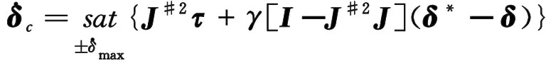
wheresatis saturation function,δ*is a set of desired gimbal angle andγis a properly selected scalar.
Two kinds of steering logics were proposed in Ref.[24]using game theory analysis. One is the steering logic based on cooperative game theory,which treated the singularity avoidance as parameter optimization problem. And the other one was based on transfer utility multi-player game theory.
5.10 Summary of CMG Steering Logic
In order to determine the gimbal rate for given control torque command, several steering logics have been proposed based on different theories and are summarized in Fig.20, where the arrow implies derivative relationship.
From the discussion above, it can be summarized that an optimal CMG steering logic should have the following characteristics:
1) Singularity avoidance/escape;
2) Error-free torque output;
3) Universality for different configurations;
4) Satisfaction for hardware restriction.
Two different research directions for CMG steering logic including hybrid logics and steering strategies based on modern theory should be intensively studied.It necessitates the modification of the classical laws to meet above requirements for space activities.
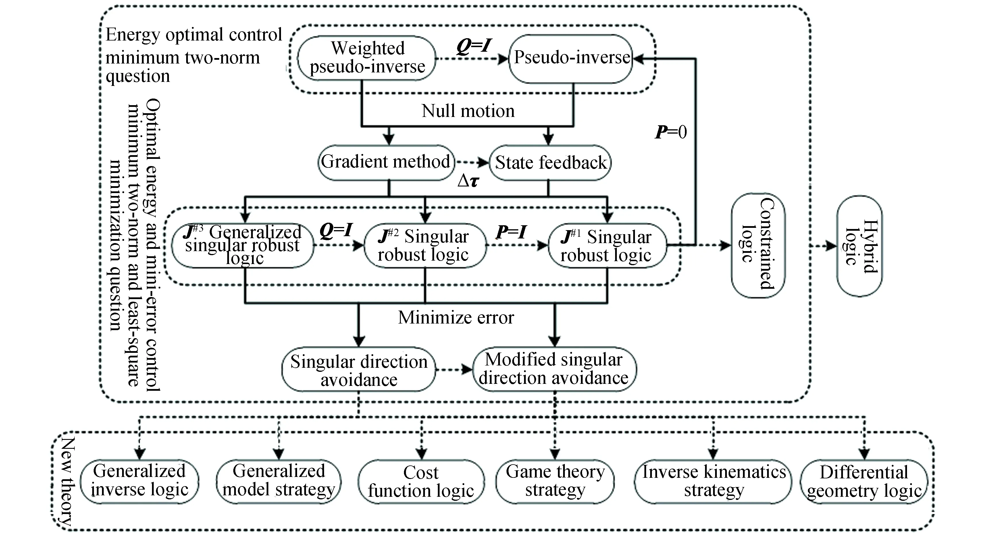
Fig.20 Diagram for CMG steering logic
6 Conclusions
High-resolution image acquisition, rapid maneuvering for spacecraft imaging and other space observation missions depend on the powerful output of CMG. We have reviewed SGCMG control problems for agile spacecraft in the current literature. A theory framework about single gimbal control moment gyroscope, relating to configuration, evaluation and modeling, singularity visualization and singularity steering logics, are surveyed.The research presents comprehensive theories and knowledge. What’s more, it’s advised that the pyramid CMG cluster and FPC-Z cluster are two effective candidates for agile spacecraft for their static performance. The generalized singular steering logic is an efficient method to escape all kinds of singularities. What should be further dealt with is the practical form of this logic when considering the physical constrains.
Although the present work about CMG is quite comprehensive and well conducted, there still further work that should be done, including:
1) Refining the modeling method and finding universal and simple procedure for singularity avoidance;
2) Building the framework of configuration evaluation to select optimal clusters for specific space activities;
3) Designing more practical and efficient control logics for spacecraft in consideration of physical constrains with robustness and accuracy;
4) Studying mixed actuators based on CMG to pursue powerful torque amplification and free of singularity.
As many researches on this area are ongoing, this survey is by no means complete. The authors believe that the summarization of this work will provide new ideas for further investigation.
杂志排行

Journal of Harbin Institute of Technology(New Series)的其它文章
- Inverse Synthetic Aperture Radar Imaging of Multi-TargetsBased on Image Processing Technique
- Dynamics Analysis of Square Unit and its Combined Mechanismwith Joint Clearance
- Experimental Study on Shear Behavior of New-TypeSteel-Concrete Composite Bridge Deck
- Review:A Critical Assessment on the Predictability of 14Micromechanics Models for the Stiffness and Strength ofUD Composites
- Theoretic Diffraction Research on the Order-Disorder Effect ofTransition Metal in Li(Ni1/3Co1/3Mn1/3)O2
- Three-Dimensional Normal Stress for Controlling Electronic Structureand Magnetic Property of Fe2Ge