Application of Laser Ultrasonic Technique for Non-contact Detection of Angled Surface Defects
2018-11-21,,
, ,
College of Automation Engineering, Nanjing University of Aeronautics and Astronautics, Nanjing 211106, P.R. China
Abstract: Based on the finite element method, the angled surface defects have been investigated by using the laser generated surface acoustic wave (SAW). The feature of laser generated SAW interaction with the angled defect is analyzed in time and frequency domains. An increase in the amplitude of SAW at the edge of the defect is observed, and the spectral feature is angle dependent. With the angle decreasing from 120° to 30°, the maximum amplitude of frequency spectrum of SAW increases gradually. The corresponding experimental results verify the feasibility of numerical analyses and reach a good agreement with simulation results.
Key words: laser ultrasound; surface acoustic wave; angled surface defect; spectrum
0 Introduction
The non-destructive testing (NDT) of materials is an integral part of quality control for many industries, such as aerospace, nuclear, power generation and petrochemical industries. Both contact and non-contact techniques have been developed to detect surface-breaking defects, for example various ultrasound techniques, eddy current testing, magnetic particle inspection. Among them, laser ultrasonic technique (LUT) has been widely used because of several advantages, such as non-contact, high sensitivity, and is suitable for detection of complex surface and in-situ inspection[1-7]. The incident laser generates multimode ultrasonic waves such as longitudinal wave, transversal wave and surface wave at the same time. Among them, the surface acoustic wave (SAW) is suitable for surface defect evaluation due to its high sensitivity to the surface defect.
Many researchers have made efforts to investigate the features of laser-generated SAW and got some achievements, especially in NDT of defects which are inclined at an angle to the surface, such as rolling contact fatigue in rails and stress corrosion cracking. Jian et al.[8]proposed a crack depth gauging method using wideband Rayleigh waves generated by laser, and discussed the possible mode-converted ultrasonic waves scattering in different parts of the crack during the propagation. Matsuda et al.[9]developed an adaptive laser ultrasound system to evaluate crack characterization. The position, the depth and the orientation of the crack were determined using laser-generated Rayleigh wave. Ni et al.[10]analyzed the angled surface-breaking cracks detection by dual-laser source generated ultrasound and provided a method to calculate the crack-orientation angles. Dutton et al.[11]explored the interaction of Rayleigh waves with angled cracks, and found the reflection and transmission of Rayleigh waves show some angle dependence. Edwards et al.[12]studied the interaction of laser-generated ultrasonic waves with wedge-shape samples, and gave the dependence of the arrival times and amplitudes of the reflected and mode-converted waves on the wedge angles. However, the previous researchers on defects which are inclined at an angle to the surface have mainly concentrated on wedges, while seldom concerned the angle influence on frequency characteristics of laser-generated surface acoustic wave, and the quantitative relationship about different angled surface defects has not achieved. In this paper, the features of laser-generated ultrasonic surface wave interaction with angled surface defects are analyzed. Moreover, the influence of different angles on recognizing defects is taken into account, and the quantitative characterization of defect angles by gauging the frequency components of SAW is given.
1 Theoretical Background
1.1 Laser ultrasound generation based on thermoelastic mechanism
Thermoelastic mechanism happens when the specimen surface is illuminated by a laser pulse with an energy density less than the ablation threshold of material. It is described as parts of laser energy absorbed by material, continuously transferring into surrounding medium which forms transient temperature field with non-uniform distribution, and the stress field induced by periodic thermal expansion gives rise to ultrasonic wave excitation. So, thermoelastic mechanism can be summarized as the thermal conduction equation and displacement control equation as follows[13]
(1)
μ2u+ (λ+μ)(·u)-
α(3λ+2μ)
(2)
whereKis the thermal conductive coefficient,Qis the heat source,Tis the temperature field;uis the displacement field,ρis the material density,Cvis the specific heat,λandμare the Lamé constants, andαis the linear thermal expansion coefficient.
1.2 Finite element method
Finite element method (FEM) has already been used to calculate the generation and propagation of laser ultrasonic wave in material[14-17]. The interaction of a surface ultrasonic wave with an angled defect is also investigated using FEM models in this paper. The model configuration is set up as shown in Fig.1. The FEM dimensions of aluminum plate are set to 20 mm×10 mm, and the artificial surface defects have the width of 1 mm, the depth of 2 mm and the inclined angleθof 30°, 45°, 60° and 120°, respectively. The elastic and thermal properties of aluminum plate used in FE calculations are shown in Table 1. The power density of 7 MW/cm2and Gaussian temporal pulse shape of pulsed laser with pulse duration of 8 ns and 0.1 mm of the laser spot radius are used in FE calculations.The distance between the laser source anda,b,c,d,eis 5, 9, 9.5, 10 and 11 mm, respectively.

Fig.1 Schematic diagram of laser irradiating aluminum plate with angled defect
The FEM calculation process is divided into two stages with the quasi-steady assumption. The first stage calculates the distribution of temperature field within a specified time range, and the temperature field is the source of external loads of the second stage in which the propagation of elastic waves is calculated. The calculations are performed by the software package ANSYS. Thermal analysis step size is set to 0.1 ns, and the analysis of time is 10 ns. The stress field analysis time is 0.01 μs, and the analysis of time is 10 μs.

Table 1 Elastic and thermal properties of aluminum plate
2 Experimental System
In order to verify the validity of numerical simulation results, a non-contact experimental system for investigating the interaction of laser-generated SAW with surface-breaking defects of aluminum plate is constructed, as shown in Fig.2. The excitation device is composed of a Q-switched Nd: YAG infrared pulse laser with wavelength of 1 064 nm, the maximum pulse duration of 8 ns and adjustable excitation frequency covering a range of 1—20 Hz. It is used to induce surface acoustic waves and the energy density of the pulsed laser is controlled under 10 MW/cm2to ensure that the ultrasonic wave is generated in the thermoelastic mechanism. For detection, a multi-channel random interferometer (Quartet made by Bossanova) is used to realize non-contact detection. Based on a translation stage, the interferometer probe can detect the surface ultrasonic waves of different locations. The control section of the experimental setup is performed by AT89C52 SCM, DAC chip TLC5615 and PC.

Fig.2 Schematic diagram of experimental system
3 Results and Discussion
3.1 Numerical results
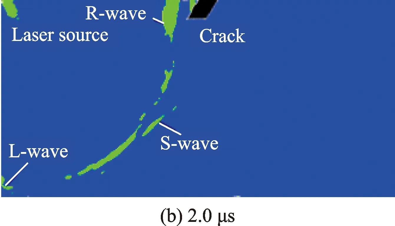
Based on the above-described theories and material parameters, the propagation characteristics of SAW in aluminum plate with angled surface defects are calculated using FEM. Fig.3 shows the numerical simulation results with the angle of 60°. It can be seen that the incident laser generates multimode ultrasonic waves at the same time. L, S and R stand for longitudinal wave, transversal wave and surface acoustic wave, respectively. Among them, only SAW propagates along the top surface of the specimen. SAW reaches the position of the angled defect when the timetis 3 μs. A portion of them is reflected and propagates back along the top surface of the sample, while another propagates down along the boundary of the defect to the defect bottom. Then, at the bottom of the defect, a part of the wave will be transmitted underneath the defect, while another part will have a mode conversion and scatter into the specimen[18]. And most of SAW is reflected by the defect when the timetis 3.5 μs, only a little can keep going.


Fig.3 Numerical simulation results of laser generated ultrasonic waves in aluminum plate with angled defect at different time

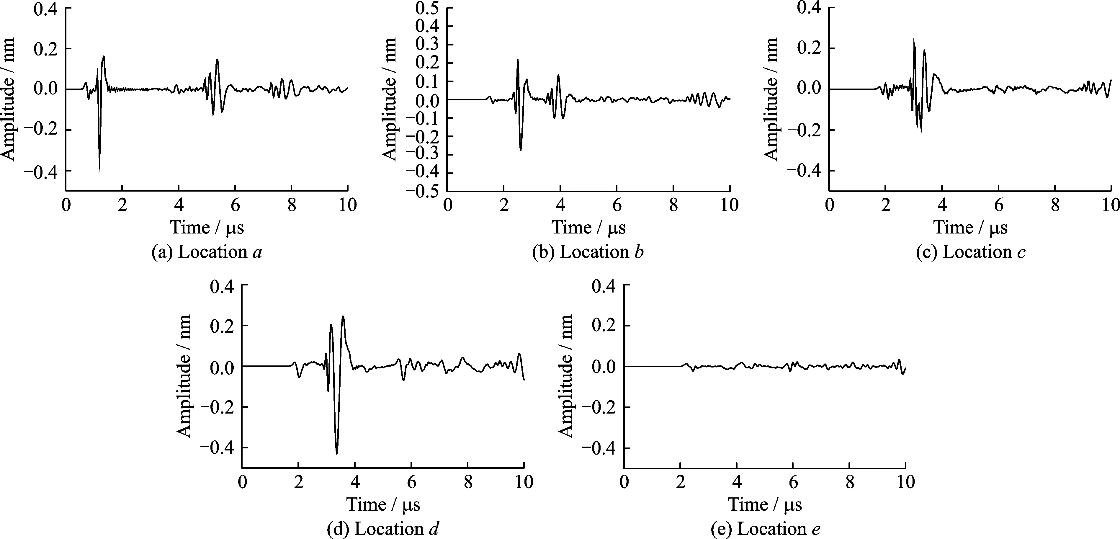
Fig.4 Time domain signal of SAW interaction with the angled surface defects with angle of 60° at different locations
Then, in order to explicitly show the interaction of laser-generated SAW with angled surface defects, the propagation characteristic of SAW at different positions on the surface of the specimen with a given angled defect is presented. Fig.4 shows the time domain signal of SAW interaction with the angled surface defect with the angle of 60° at different locations, i.e.,a,b,c,d, andein Fig.1. Fig.4(a) shows the time domain signal of SAW at locationa. It can be seen that the SAW signal appears att=1.5 μs, and the reflected signal caused by the surface defect appears att=5 μs. The maximum amplitude of the SAW is about 0.35 nm. Figs.4(b),(c) show the time domain signals of SAW at locationsbandc. Because of constructive interference of the incident and reflected SAW, the maximum amplitude of the SAW reduces to about 0.23 nm. As shown in Fig.4(d), the maximum amplitude of the SAW increases to about 0.48 nm when SAW arrives at the edge of the angled defect, and the wave period also changes. Fig.4(e) shows the SAW signal at locatione. The transmitted wave signal is small. Based on the above mentioned, the conclusion can be given that the amplitude of the SAW will enhance when the SAW arrives at the edge of the angled surface defect. In order to understand this behavior, one can first consider the behavior of SAW interact with an angled defect. Some authors have reported the increase in amplitude (enhancement) at a defect oriented normal to the sample surface, due to multiple wave interaction: incident and reflected waves plus a mode converted surface skimming longitudinal wave, which positively interfere with each other[4,19-20]. For an angled defect, as the wave moves into a wedge-region, the local thickness changes and will affect what wavemodes can propagate. The Lamb-wave-like modes were reported[21], and the interference of the Lamb-wave-like modes will also lead to signal enhancement, with the focusing of the wave energy into the wedge tip giving a large enhancement for shallow angles. This enhancement could be used as a fingerprint of the presence of such defect.
Since the signal enhancement appears when the SAW arrives at the edge of the angled surface defect, the SAW signal at locationdis chosen to analyze the influence of different defect angles. Please note that when interpreting the interaction of a surface ultrasonic wave with an angled defect, both size and angle of the surface defect need to be considered. It has been shown previously that the measurement of the depth of a defect must consider the crack angle when choosing a suitable depth calibration profile[22]. Hence, we consider mainly the effect of the angle of a defect in this paper.
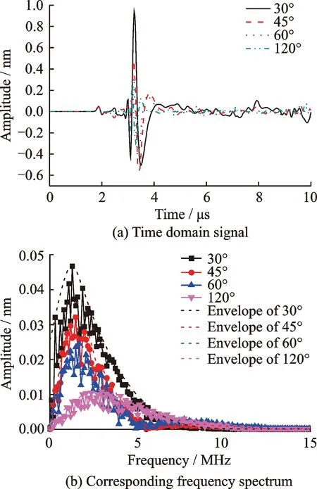
Fig.5 presents time domain signals and their frequency spectrums of SAW interaction with angled surface defects with different angles at locationd. It is obvious that the magnitude of the enhancement for angled defects is angle dependent, and can be very large for shallow angles as the wave energy is focused into the angle vertex. For these types of defect, the incident wave is affected by the changing frequency-thickness product in the angled defect, mode-converting into A0 and S0-like modes. The large enhancement is then due to interference of these Lamb-wave-like modes, in addition to the changes in the in-plane and out-of-plane displacements due to the different thickness of the sample at each measurement position[23].

Fig.5 Laser generated SAW interaction with angled surface defects with different angles at location d
It is clear that in the region of frequency content the peak value of frequency spectrum of SAW increases with the defect angle decreasing from 120° to 30°, and the higher frequencies are persisted for shallower angles in the range 0°≤θ≤90°. This frequency-dependent behavior is, to some extent, expected, considering the filtering action of a defect. As shown in Ref.[24], when a broadband Rayleigh wave is incident on a surface-breaking defect, the higher frequencies tend to be blocked (reflected), while the lower frequencies tend to be transmitted. If considering enhancement due to only interaction of incident and reflected Rayleigh waves, it is therefore to be expected that the enhanced signal will contain significant higher frequency content. The addition of mode-converted waves will complicate the problem, but these are also likely to tend towards the higher frequency content[17].
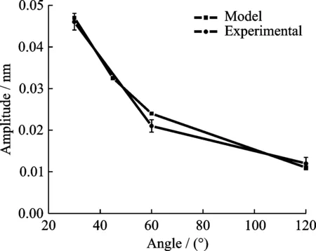
Then, the relationship between the peak value of frequency spectrum of SAW and the defect angle can be obtained. As shown in Fig.6, the maximum peak value of frequency spectrum decreases with the increase of the defect angle. Therefore, it can be speculated that the angle could be effectively recognized by measuring the frequency spectrum of SAW.

Fig.6 Relationship between peak value of frequency spectrum of SAW and defect angle
3.2 Experimental results
On the basis of the described experimental system, some experiments are carried out to verify the physical approach and the accuracy of the numerical simulation. An aluminum plate with angled surface defects is chosen as a specimen, and the artificial defects are finished with the depth of 2 mm, the width of 1 mm and the angle of 30°, 60°and 120°, respectively. The positions of laser source and detection are shown in Fig.1.

Fig.7 Experimental signal of SAW interaction with angled surface defects with angle of 60° at different locations
Fig.7 shows the experimental results of SAW interaction with the angled surface defects with the angle of 60° at different locations. As shown in Fig.7, when the detection lies in the locationa, the laser-generated SAW appears at the time about 1.5 μs, the reflected wave caused by the angled defect occurs at about 5 μs, and the maximum amplitude of SAW is about 0.33 nm. Next, in the locationsbandc, the maximum amplitude of SAW reduces to about 0.24 nm. Then, the maximum amplitude of the SAW increases near to 0.5 nm in the locationd, and the wave period also changes. And the SAW signal is so small that it almost cannot be seen in locatione. Therefore, the amplitude enhancement of the laser generating the SAW in the region of a surface angled defect can be proved.

Fig.8 Experimental waveform of SAW interaction with angled surface defects with different angles at location d

Fig.9 Relationship between peak value of frequency spectrum of SAW and defect angle
The experimental waveforms of SAW interaction with the angled surface defects with different angles at locationdare shown in Fig.8(a) and their frequency spectrums in Fig.8(b). Due to the limitation of the experimental sample, the experimental results of the angle of 45° are not shown here. It can be seen that with the decrease of the defect angle, the amplitude of the SAW in time and frequency domains both increase and the change is obvious. And in the range 0°≤θ≤90°, the spectrum persists higher frequencies for shallower angles. These can confirm the angle dependence of the signal enhancement for angled defects in the simulation. The relationship between the peak value of frequency spectrum of SAW and the defect angle for both model and experimental data are shown in Fig.9. The reduced experimental enhancement at some angles is mainly due to focusing issues, leading to a larger detection point size when compared with the model. It is obvious that the maximum amplitude exhibits an increasing trend as the defect angle decreases for the experimental data, just like the simulation results.
Based on the numerical and experimental results mentioned above, both model and experimental data confirm that the enhanced amplitude of SAW at the edge of the defect show promise for use in identifying the position of the angled surface defect, and the peak value of frequency spectrum has a significant dependence on the defect angle, which could potentially be used to find different angled defects in real samples.
The interaction of SAW with a very shallow angled defect is not included in this paper. For a very shallow angle, difficulties in producing reliable samples and models with high enough node densities preclude an extension of the discussion. In theory, at a very shallow angle the vertical depth of the defect is very small compared to the wavelength, the majority of the waves is able to penetrate beneath the defect, and the amplitude enhancement may be diminish. More details require further investigation, which will be discussed in later work.
4 Conclusions
This paper investigates the interaction of laser-generated SAW with angled surface defects. The pulsed laser generated SAW is sensitive to surface-breaking defects. Based on FEM and experimental results, enhancements in the amplitude of the SAW very close to the defect can estimate the angled surface defect. With the decrease of the defect angle, the maximum amplitude of frequency spectrum of SAW increases monotonously. The relationship between the maximum amplitude and the defect angle could be applied to the quantitative characterization of angled surface defects. This study provides an effective method to realize the angled surface defects testing. Besides, when exploiting the interaction of ultrasonic surface waves with surface angled defects, the defect size such as the length also needs to be considered, which will be focused in our future work.
Acknowledgement
This work was supported by the National Natural Science Foundation of China (No.51505220).
杂志排行
Transactions of Nanjing University of Aeronautics and Astronautics的其它文章
- Random Vibration of Steel Catenary Riser Conveying Fluid Under Wave Excitation
- Failure Assessment of Aero-engine Support Structure due to Blade-off
- Nonlinear Control Method for Hypersonic Vehicle Based on Double Power Reaching Law of Sliding Mode
- Dynamic Analysis and Optimization of Pneumatic Wedge-Shaped Launcher for UAV
- Modal and Fatigue Life Analysis on Beam with Multiple Cracks Subjected to Axial Force
- Two Classes of Quaternary Codes from 4-valued Quadratic Forms
