Behavior of reinforced concrete beams and columns subjected to blast loading
2018-10-18YanLiuJunboYanFengleiHuang
Yan Liu,Jun-bo Yan,Feng-lei Huang
State Key Laboratory of Explosion Science and Technology,Beijing Institute of Technology,Beijing,100081,PR China
Keywords:Blast Steel reinforced concrete beams Dynamic response Scaling SDOF
ABSTRACT In this study,the blast performance of steel reinforced concrete(RC)beams was experimentally and analytically investigated.The experiment consists of a total of 10 one-half-scale beams subjected to different levels of blast loading using live explosives.The reflected pressure-time histories were recorded and different damage levels and modes were observed.The blast resilience of the damaged beams was quantified by measuring the time-dependent displacements.Experiment results show that the damage in steel reinforced concrete beams with higher explosive mass is enhanced compared with that of the beams with smaller explosive mass at the same scaled distance.Based on the experiment data,an empirical expression is developed via dimensional analysis to correct the relationship between the midspan displacement and scaled distance.Besides,a complex single degree of freedom model(SDOF)incorporating complex features of the material behavior,high strain-rate effect and the column geometry was proposed and validated by test results.
1.Introduction
The blast protection of structures is essential for engineering communities and government agencies as a result of more and more frequent terrorist activities and recent accidental explosions[1].The most common failure mode of structures subjected to blast loading is progressive collapse which is typically initiated by the abrupt failure of load-bearing beams and columns.Therefore the reliability of vulnerable beams under blast is of great importance for the survivability of the building[2],[3].
Currently,the equivalent single degree of freedom(SDOF)approach has been widely employed to assess the effects of blasts on structures.For example,several technical manuals such as UFC[4]based on the linear resistance curves are used to design the protective structures subjected to blast loads and idealized load-deformation characteristics are given as the form of design charts.Dragos[5]proposed a simplified SDOF approach based on the new concept of reduced resistance-deflection function to derive the P-I diagram for steel columns.Besides Wang[6]studied the SDOF approach to evaluate the concrete structure members under close-in non-uniform blast loads and the comparison with the test results indicated that the SDOF method can give reasonable predictions.In general,the structural elements are typically simplified as having perfectly elastic-plastic force-deformation relationships in most of previous literature.However,this idealized member resistance has its inherent limitations which are very important for the analysis.For instance,such idealized SDOF is incapable of considering the gradual effect of the formation and progression of plastic behavior that it can capture.Moreover,the variations of the cross section's properties such as geometries,material properties and strain rate effects are ignored.Therefore,employing this idealized force-deformation characteristic will cause some uncertainties to the calculations.
Besides,it is necessary to employ the field experiment to validate the analytical models.Extensive experimental research has been conducted to study the dynamic response of concrete beam subjected to blast loading.
However,very few experimental researches on the blast response of structures have been conducted.Hassan Aoude[7]analyzed the blast load performance of ultra-high performance fiber reinforced concrete(UHPFRC)columns using a shock-tube.The results demonstrate that the use of UHPRFC significantly improves the blast performance of reinforced concrete columns.Alicia Echevarria[8]carried out an experimental investigation to investigate the blast performance of concrete- filled fiber-reinforced polymer tube bridge columns.The results indicated that the CFFT columns exhibited superior strength and ductility retention compared with the damaged RC columns.Amr A.Nassr[9][10]performed full-scale field tests on wideflange steel beams and columns to investigate their behavior and resistance under blast loading and considered the effects of charge size and stand-off distance on their behavior.
In general,the detailed experimental data of the blast response of reinforced concrete beams needed to validate the analytical and numerical approach are scarce.Moreover,the influence of charge mass under same scaled distance on the blast response of concrete structures has not taken into account in available formula in most of previous literature.
Therefore,in this paper,half-scale steel reinforced concrete beams were tested in the field using live explosives.The blast response of steel reinforced concrete beams were analyzed through time dependent displacements.Then the relation between the dimensionless maximum mid-span displacements and the scaled distance was obtained via dimensional analysis theory,in which the scaled factor that characterizes the influence of charge mass was incorporated.Moreover,a flexural behavior(moment-curvature relationship and force-deformation relationship),in which complex features of the material behavior under high strain-rate loading and column geometry are considered,is incorporated into a SDOF approach for dynamic analysis of columns subjected to blast-induced shock waves.This proposed empirical formula and the proposed SDOF method were tested against the available test data.
2.Experimental program
2.1.Description of test specimens
The uniaxial compressive strength after standard curing of 28-day and density of concrete material used in this experiment are 30 MPa and 2.5 g/cm3,respectively.The dimension of each concrete target is 1700mm long,150 mm wide and 150 mm thick,as shown in Fig.1 and Table 1.All the beams were doubly reinforced with two 8mm diameter steel non-deformed reinforcement with an exterior 6mm diameter hook spaced at a distance of 180 mm from one another in the major bending plane.Clear cover to reinforcement was maintained at 20 mm.The uniaxial compressive strength after standard curing of 28 day and density of concrete material used in this experiment are 30 MPa and 2.5 g/cm3,respectively,as measured using six normal 150 mm×150 mm×150 mm concrete cubes,a tensile strength 4.1MPa and a Young's modulus of 28 GPa.
2.2.Test setup
Fig.2 presents the typical setup for the beam tests.All beams were tested under transverse shock-wave loads using TNT.The beams were supported by the concrete base.The concrete base was poured out of a groove base as solid support for the lower side of the specimens.The beam was considered as simply-supported.

Table 1 Tested RC beams.
To prevent the wraparound of pressure wave and protect the testing devices and wiring under the specimen,two steel plates with a dimension of 1500 mm long,500 mm wide and 10mm thick were placed on both sides of the specimens as shown in Fig.2.The influence of wraparound phenomenon on the blast wave is significant and shouldn't be ignored for the reason that shock waves would engulf the target before the pressure substantially drops on the target surface facing the charge.The steel plates can also minimize the clearing effect,which is known to be caused rarefaction waves traveling back from the edges of the reflecting surface and causing considerable pressure relief,which,in turn,leads to a significant loss of total specific impulse.
During the test,the TNT explosive was suspended at a certain height above the center of the component and was detonated by the electric detonator.The actual displacement at the mid-span of reinforced concrete members is tested by KD 9-20 tension line displacement sensor as shown in Fig.3.The displacement sensor can convert the actual displacement into measurable electrical signals.Two displacement meters are fixed at the mid span of the concrete component,and the errors are minimized.In the experiment,Digital Pressure Recorder(DPR)was used to record and store shock wave pressure test signals,which is developed by the Key Laboratory of Explosion Science and technology,Beijing Institute of Technology,as shown in Fig.4.The sensitivity of the digital pressure recorder is dynamically calibrated by the shock tube.As Fig.4 shown,DPR was used to measure the reflection pressure of the edge of the component.
2.3.Test matrix
10 reinforced concrete beams were tested under different blast conditions generated by different combinations of stand-off distance and charge weight as shown in Table 2.In order to investigate the blast response of RC beams under different scaled distance,four RC beams(B1-1,B1-2,B1-3,B1-4)were tested under different scaled distance.To study the influence of charge mass under the same scaled distance,four RC beams(B1-1,B2-1,B2-2,B2-3)were tested under different charge weight and same scaled distance which equals to 0.68.And another four RC beams(B1-4,B3-1,B3-2,B3-3)were tested under different charge weight and same scaled distance which equals to 0.63.
3.Experimental results
3.1.Reflected pressure and positive phase duration
The model proposed by Wang[11]was utilized to calculate the equivalent uniform blast load for non-uniform blast load for close in explosion of steel reinforced concrete beam in this paper.This model is based on equating the external virtual work done by the equivalent uniform blast load to the external virtual work done by the non-uniform blast load such as close-in explosions.The model has been validated using experimental data in Ref.[11].The peak equivalent uniform blast load is calculated by peak pressures of the four characteristic points of the beam.
Table 2 Matrix of tested beams.
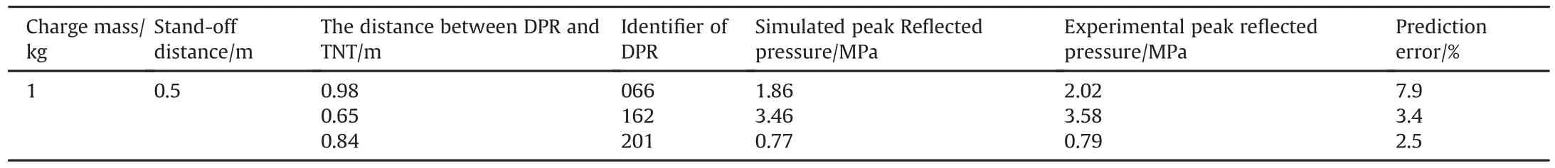
Table 3 Comparison of peak reflected pressure.
The center blast load impulse is chosen as the equivalent blast load impulse according to Ref.[11]:
In order to obtain the peak pressure of the four characteristic points of the beam,numerical models of a series of beams are established using software AUTODYN.In the numerical model,air and high explosive(TNT)are modeled with an Eulerian mesh and the column and steel plate are modeled with a Lagrangian mesh.Fully coupled Euler/Lagrange(3D)interaction,which is provided by AUTODYN,is used to model the blast wave and beam interaction.A numerical convergence check was also performed to determine the mesh size.The air and TNT charge were meshed with an element size of 15mm.In the numerical study,the beam response was not analyzed.In order to validate the reliability of the numerical method to simulate the blast loads,some gauges were installed at the same position in the numerical model as the DPR in the experiments.The distance between DPR and TNT and comparison of the peak pressure between numerical results and test data were listed in Table 3.Typical comparison of the simulated reflected pressure time history and the test result is shown in Fig.5.
This comparison indicates that the numerical method can give reliable simulation of the peak reflected pressure acting on RC beams.However,it is observed that there are “after-shocks”after the peak pressure.These may be caused by detonation products because of close-in blast which is not considered in this model and should be further studied.Herein,equivalent uniform peak pressure and load duration are calculated as listed in Table 4.The result will be incorporated into the SDOF model to obtain maximum midspan displacement of RC beams.
3.2.Blast response of RC beams under different scaled distance
Fig.6 shows the post-test observation on typical targets.The scaled distance with the level of 0.5,0.54,0.63,0.68 were utilized to perform the test on the above concrete components.It is observed that when the scaled distance is 0.68 as shown in Fig.6(b),obvious central bending failure occurred after the explosion.However,there was no obvious crushing area on the upper side of the beam and spallation on the bottom side of the beam.There was a crack from top to the bottom at the mid-span with an average width of 14.2 mm.As the scaled distance decreased to 0.63,spallation occurred at the bottom of the beam with a length of 320 mm.But there was no crushing area on the top face of the beam.When the scaled distances were 0.54 and 0.5,both spallation on the bottom face and crushing on the top face occurred.The length of spallation for the two scaled distance is 370mm and 382 mm respectively and the length of crushing area is 48mm and 70mm respectively.Because the compressive stress waves in the reinforced concrete beams propagate to the back of the beam,a strong tensile wave is formed,which causes the spallation and cracking of the concrete.With the increase of scaled distance,the failure of reinforced concrete beams develops from the crack failure to the spallation failure.Meanwhile,the failure zone of the reinforced concrete beams increases with the increase of charge mass.
The comparison of maximum mid-span displacement under different scaled distance is shown in Fig.7.As Fig.7 shows,that the maximum mid-span displacement of the RC beam after blast increases as the scaled displacement decrease.

Table 4 Calculated peak equivalent uniform reflected pressure and load duration.
3.3.Blast response of RC beams under same scaled distance and same charge mass
In order to study the effect of charge mass on the blast response of RC beams under the same scaled distance,RC beams were subjected to blast load generated by different charge mass under the same scaled distance.
Fig.8 shows the post-test observation on typical targets.When the scaled distance equals to 0.68,the charge mass with the amount of 0.69 kg,0.87 kg,0.53 kg were utilized to perform the test on the concrete components.It is observed that when the amount of charge mass is 0.53 kg and 0.69 kg,there is obvious central bending failure with no crushing and spallation.The width of crack happened at the mid span is 6 mm and 19.4 mm respectively for the above charge mass.When the amount of charge mass is 0.87 kg,spallation happened at the bottom of beam whose length is 260 mm.
For the blast whose scaled distance is 0.63,the charge mass with 318 mm respectively.
Also,the comparison of maximum mid-span displacement for the two scaled distance is shown in Fig.10 and Fig.11.It is concluded that when the scaled distance remains the same,level of damage increases as the charge mass increases.Therefore,the level of damage is related to the charge mass besides scaled distance.When studying the blast response of RC beam,the influence of charge mass shouldn't be ignored.
4.Discussion
In the experiment,the damage level of RC beams increases with the decrease of scaled distance.Besides,RC beams suffer more from blast when the charge mass is larger under the same scaled distance.Thus,the effect of charge mass should be taken into account when analyzing the blast response of RC beams.When scaling the blast wave phenomena,the most common the amount of 0.67kg,0.86 kg and 1.1kg were employed to generate the blast.As Fig.9 shows,both crushing and spallation happened for the above three charge masses.The length of crushing area for the amount of charge mass of 0.67 kg,0.86 kg and 1.1 kg is 19mm,53 mm and 83 mm respectively.And the length of spallation for the above three charge mass is 162 mm,315 mm and scaling method is Hopkinson's or the “cube root”scaling law,as shown by Baker[12][6].According to Baker,for TNT with the same geometry which has different weights,same blast wave will be produced at the same scaled distance as shown in following formula:When
where Z is the scaled distance,t is the scaled positive pressure time,is the scaled impulse,M is the charge mass and R is the distance from the charge center.This law implies that positive pressure time and impulse is related to both scaled distance Z and charge mass M.When assessing the blast response of RC beams,both blast pressure and impulse should be considered.In this paper,a new scaled coefficient is proposed to in order to incorporating the effect of charge mass on the impulse based on the cube root”scaling law:
where 0.4 kg is chosen to benchmark herein.Therefore,M0=0.4 kg.Scaled maximum displacement can be calculated as:
where α ,β1,β2are the dimensionless undetermined constants which can be obtained by the experiment data.
When the scaled distance is 0.68 and charge mass equals to 0.4 kg,0.53 kg,0.69kg and 0.87kg,the maximum dimensionless displacement is 0.018,0.0187,0.0232 and 0.032 respectively as shown in Fig.12.
Based on the four experiment data,β2can be obtained,which equals to 2.56.Therefore,the relationship between dimensionless maximum displacement and scaled distance can be expressed as:
In order to determineαandβ1,the experiment result of B1-1,B1-2,B1-3 and B1-4 beams are employed as shown in Fig.13.
According to the above experiment data,α and β1can be determined.Thus,maximum displacement can be calculated as:
In order to validate the empirical formula,experiment data from B3-1,B3-2 and B3-3 beams was adopted and comparison of maximum displacement between experiment data and result from empirical formula is presented in Table 4.The maximum discrepancy between the experiment result and analytical result is 3%and the average discrepancy is 1.83%.This difference was within a reasonable level of accuracy.This indicates that the empirical formula can give reliable predictions of the maximum displacement of RC beams subjected to blast loads.
Of course,it should be noted that Eq.(5)applies only to the data range of experiment which is 0.5≤≤0.68 and R≥0.5m.Besides Eq.(5)has been used to calculate the maximum displacement of the beam described in section 2 and would be inappropriate for more general use.
5.Comparison with the single-degree-of-freedom model
5.1.Dynamic SDOF analysis
The dynamic motion of axially loaded columns subjected to blast pressure can be simplified as a SDOF system by assuming one ordinate,usually taken as the ordinate of the maximum transverse displacement[13][14].The system can be described by a spring mass system in which the equivalent column mass,equivalent blast load and adopted resistance function is incorporated,as shown in Fig.14[15].The damping effects were neglected in the present SDOF model because the duration of the blast event is very small compared to the natural time period of the beam[15].
The idealized SDOF system is described by the following equation of motion:
Where KMis the mass factor,KLis the load factor,M is mass,x is the displacement,is the acceleration,R(x)is resistance as a function of displacement,Fc(t)is the loading as a function of time.
It is convenient to define equivalent mass which is Meq=
Then the response of the system may be rewritten as
Where m(x)is the distributed mass,φ(x)is the shape function.
The assumed sinusoidal shape function are given in Equations[16]:
New mark proposed the following numerical solution technique for this equations[17]:
(2)ti+1=ti+ △t,and assume avaluefor the acceleration at time
(3)Compute a velocity at ti+1,:
(4)Compute a displacement at ti+1:

Table 5 Comparison of maximum displacement between experiment data and result from empirical formula.
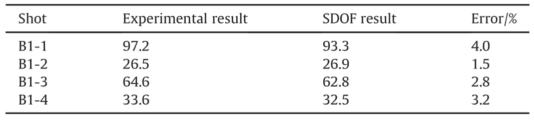
Table 6 Comparison of calculated and tested maximum mid-span displacement.
(5)Substitute yi+1andinto Equation and compute a new value for
5.2.Validation of SDOF approach
In order to validate the accuracy of the above mentioned SDOF approach,maximum mid-span displacements generated from this SDOF analysis were compared with the results from test of B1-1,B1-2,B1-3 and B1-4.
Comparisons of calculated and tested deflection time histories are shown in Fig.15 and comparisons of maximum displacement obtained from SDOF approach,proposed empirical formula and test results are listed in Table 5.The maximum displacement obtained by the SDOF method is in good agreement with the measured value and the average deviation is less than 4.0%.The reasonable difference indicates that the proposed SDOF approach can give reliable calculation of the maximum displacement of RC beams subjected to blast loads(see Table 6).
6.Conclusions
In this paper,several field tests were performed to investigate the blast response of RC beams.During the experiment,the influence of scaled distance and charge mass on RC beams is also studied under different scaled distance and charge mass.The experiment result shows that RC beams only suffer flexural deformation.With the decrease of the scaled distance,damage mode changes from a few cracks on the surface to spallation on the back surface.Also,crushing on the top surface occurred.Besides,RC beams suffer more with the increase of charge mass under the same scaled distance.
A computational formula for calculating mid-span maximum deformation was proposed via dimensional analysis in which the effect of scaled distance and charge mass was considered.The reasonable agreement between the analytical and experimental results indicates that the formula can accurately predict the midspan maximum displacement of RC beams subjected to blast loading.However,this empirical formula only applies to the RC beams used in this experiment.In order to incorporate material constitutive models,the strain rate effects,gradual effect of the formation and progression of plastic behavior,a nonlinear SDOF model was developed.In order to validate the SDOF method,the theoretical SDOF maximum displacements were compared with test results.The results agree well together and indicate that this SDOF model can accurately predict the deflection of the blast loaded RC beams.
Acknowledgement
This paper is supported by The National Natural Science Foundation of China under Grant No.11390362 and No.11221202.
杂志排行
Defence Technology的其它文章
- GUIDE FOR AUTHORS
- A novel strategy of smart manipulation by micro-scale oscillatory networks of the reactionary zones for enhanced extreme thrust control of the next-generation solid propulsion systems
- Method of ballistic control and projectile rotation in a novel railgun
- Conceptual design of 2 MJ capacitive energy storage
- LTT switch unit for capacitive energy storages
- Safety analysis on truing process of solid propellant