Conceptual design of 2 MJ capacitive energy storage
2018-10-18RamazanovFridmanKharchevaKomarovSerebrov
R.F.Ramazanov,B.E.Fridman,K.S.Kharcheva,O.V.Komarov,R.A.Serebrov
D.V.Efremov Scientific Research Institute of Electrophysical Apparatus,Saint Petersburg,196641,Russia
Keywords:Capacitors Energy storage Pulse power systems
ABSTRACT The conceptual design of the capacitive energy storage intended for operation in laboratory conditions is considered.This capacitive energy storage includes the capacitor cells of 200 kJ stored energy,each incorporating one self-healing high-energy-density capacitor,one semiconducting switch unit on the basis of Light Triggered Thyristors(LTT)and the pulse diodes,as well as the toroid inductor.Power supply of the capacitive energy storage is provided by high voltage(HV)3×10 kV,50 Hz industrial electrical network,using the HV power transformer and phase-controlled rectifier.Special design for the capacitor cell and the module of capacitor cells is proposed,which provides easy access to all components of the capacitor cells during operation and maintenance.Control system of the capacitive energy system has a hierarchic structure and includes programmable logic controller(PLC),programmer for non-synchronous triggering of capacitor cells discharges and data acquisition system.
1.Introduction
Present-day capacitive energy storages are compact and highly reliable.Compactness is achieved by applying up-to-date high energy-density capacitors with metallized electrodes.High reliability is provided by self-healing capacitors and semi-conductor discharge switches.
The problem of developing a compact capacitive energy storage arose sufficiently long ago[1]after appearance of capacitors with a high energy density.Some capacitive energy storages developed in recent years are described in the proceedings of the International Pulsed Power Conference and in scientific-technical journals[2-6].Typical of all these energy storages is the following:
·Use of self-healing high-energy-density capacitors with metallized electrodes.
·Use of semiconductors in the discharge current switches.
·The capacitor bank is divided into capacitor cells,each incorporating one capacitor and one unit of semiconductor switch.
·The possibility is provided to switch on the switches in the cells not synchronously but by the preset time program(programmable discharge).
The paper considers the conceptual design of the capacitive energy storages possessing all above properties.
2.Technical requirements and characteristics
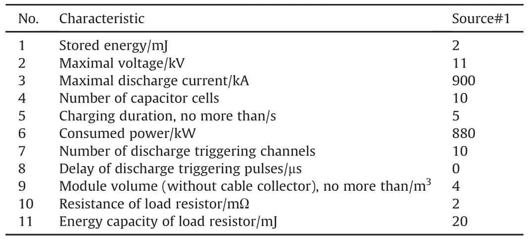
The technical requirements and characteristics of the capacitive energy storage are given in Table 1.
3.Capacitor cell
Large capacitive energy storages incorporate a set of capacitor cells.The capacitor cell of an up-to-date compact capacitive energy storage consists of,as a rule,one capacitor and one discharge current switch.Stored energy and discharge current of one cell are determined by the characteristics of the discharge current switch.
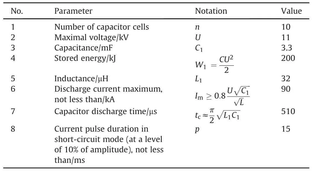
The main parameters of the capacitor cells are given in Tables 2,3,4.Fig.1 presents the equivalent circuit of the capacitor cell.
The stored energy density in the capacitor cell is determined by the energy density in the main components(capacitor,inductor)and compact arrangement of the elements of this cell.
The compactness(high component density)is attained by mutual coordination of the arrangement and sizes of the main components of the capacitor cell(capacitor,inductor,semiconducting switch unit and others).
The following arrangement was proposed for the capacitor cells(Fig.2):

Table 1 Technical characteristics of capacitive energy storage.

Table 2 Technical requirements for capacitor cells.
·the steel case of the capacitor is made as a bearing element of the cell.This bearing element is fastened on the module frame and mounts the main components of the capacitor cell.
Toroidal wound inductors,as that shown in Fig.3,will be used in the capacitive energy storage[11].The advantages of these inductors are as follows:high energy density,high Q-factor and small leakage magnetic flux.
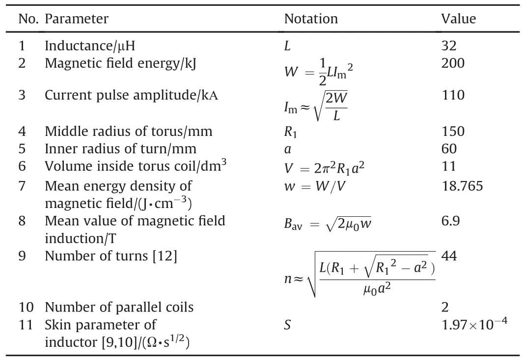
An important part of the inductor design is the contact unit in the left part of the torus,as shown in Fig.3.This unit ensures an electric contact between the current-carrying busbars and inductor wires.During assembly the contact unit provides compression of contacts with a higher force,at which the current-carrying buses are plastically deformed along the contact line,providing a reliable contact with a low contact resistance between the busbars and inductor winding conductors[13]Parameters of the inductor is presented in Table 5.

Table 3 Dimensions,volume and energy density of capacitor cells.
·the cell should be without a bearing frame or metal frame;
·all components of the cell should be arranged on and fastened to the capacitor case;
·the capacitor case should be fastened to the frame of the capacitor module.Accordingly,the sizes and structure of the capacitor were chosen(Fig.2),which provided the following:
·energy density in the capacitor w=1.5 J/cm3;
·the capacitor sizes match the arrangement of the cell equipment;

Table 4 Characteristics of pulse capacitors for 200 kJ capacitor cell.
4.Switch unit of the capacitor cell
A semiconducting switch built on TFI193-2500-42 LTT and D193-2500-50 diodes made by JSC “Elektrovipryamitel”,Saransk,Russia was chosen for application in the capacitor cell.The semiconductor switch includes six LTTs and 4 diodes.The parameters of the operation modes of LTT and diodes are presented in Table 6.

Table 5 Parameters of the inductors for 200 kJ capacitor cells.
Our studies of operation of semiconducting switches in pulsed facilities[7,8]have demonstrated that the maximal operating voltage on semiconductors should be,at least,by a factor of two less than the allowable voltage(repetitive peak off-state voltage)for this switch.Otherwise,unstables witch-on and high frequency oscillations occur,when the semiconducting structure goes to the conducting state[8].For this reason,the maximal values of voltage on the semiconducting switches presented in Table 6 were taken.
Fig.4 shows the electrical circuit of the capacitor cell with the components of the semiconductor switch unit.
5.Module of pulsed current source
The high-voltage equipment of the facility is assembled in the modules of the pulsed current sources.
The module of the pulsed current sources consists of the following components(Fig.6):

?
The capacitor cell unit(Fig.5)stores an energy of 1 MJ and consists of:

?
The cells are fastened onto the frame of the capacitor cell unit through threaded holes located on the capacitor case on the rear side and underside.The front side of the cells and their top,where the components are located,are completely open and accessible for adjustment and repair works.To replace a cell it is necessary to detach the capacitor cell unit from the module unit.
The current and voltage waveforms with the module discharge are shown in Figs.7 and 8.The results of calculation of energy release in case of discharge on the 2mΩload resistor is presented in Fig.9.This result can be used for determination of the test conditions of the module in the repetition discharge mode.
6.Charger
The charger circuits are shown in Fig.9.Voltage of high-voltage electric network of the transformer substation(3×10kV,50 Hz or 3×6kV,50 Hz)is applied through the switching apparatus to the primary windings of the three-phase high-voltage transformer Т1(10 kV/10kV).The secondary windings of the high-voltage transformer Т1are connected to the controlled bridge rectifier assembled from the photothyristors VS1-VS6.The charge is provided with a pulse-phase regulator for stabilization of the average current value at a preset level.Three current transformers ТТ1,ТТ2,ТТ3measuring the transformer phase current serve as feedback sensors for current regulation.The functional diagram of the charging current regulator is shown in Fig.10.The high voltage transformer is 1400×1500×750 mm3in dimension,1575 dm3in volume,2350 kg in mass.The charger should be located separately from themodule of the capacitive energy storage behind the protective barrier in order to ensure electrical safety of adjustment works on the module.

Table 6 Parameters of the operation modes of LTT and diodes.
7.Control subsystem
The facility consists of three devices:
·module of pulsed current source;
·charger;
·control panel.
The control panel includes:
·low-voltage control apparatus,
·programmable logic controller(PLC),
·programmer for generation of triggering pulses for nonsynchronous discharge of the capacitor cells;
·indicator of a reference kilovoltmeter for measurement of the voltage at the charger output;
·panel computer ensuring interaction between the operator and facility(display of operation and diagnostic information,entry of mode setting,etc.).
The control system incorporates the data acquisition system(KSOI)(Fig.11),which collects the diagnostic information on operation of the facility devices and transmits it to the programmable logic controller(PLC).KSOI includes:
·signal transmitters located on the high-voltage devices(capacitor cells,charger,etc.)intended for conversion of normalized analog signals of sensors and logical signals of detectors to a coded light signal transmitted via fiber-optic cables to the control panel.
·signal receivers located on the control panel,which receive coded signals of the transmitters and convert them to the information messages transmitted via the local area network to the PLC.
8.Conclusions
The conceptual design of the capacitive energy storage presented in the paper includes the experience in developing and operating large capacitive energy storages intended for physical researches under laboratory conditions.This experience gives confidence that the works on developing the like facility will culminate in the emergence of the reliable easy-to-use facility making it possible to carry out complicated physical experiments with high pulse currents.
杂志排行
Defence Technology的其它文章
- GUIDE FOR AUTHORS
- A novel strategy of smart manipulation by micro-scale oscillatory networks of the reactionary zones for enhanced extreme thrust control of the next-generation solid propulsion systems
- Method of ballistic control and projectile rotation in a novel railgun
- LTT switch unit for capacitive energy storages
- Safety analysis on truing process of solid propellant
- Ballistic model for the prediction of penetration depth and residual velocity in adobe:A new interpretation of the ballistic resistance of earthen masonry
