Electrochemical machining of a convex strips structure on a revolving part by using site directed power interruption
2018-10-15YongchengGEZengweiZHUDiZHUDengyongWANG
Yongcheng GE,Zengwei ZHU,b,*,Di ZHU,b,Dengyong WANG
aNanjing University of Aeronautics and Astronautics,Nanjing 210016,China
bJiangsu Key Laboratory of Precision and Micro-Manufacturing Technology,Nanjing 210016,China
KEYWORDS Convex strips structure;Electrochemical machining;Revolving part;Site directed power interruption;Stray corrosion
Abstract Revolving parts with complex surface structures are widely used in machinery and mechanical equipment.The ECM process provides its adequacy to cut hard materials with different shapes,and its applications are widely increased,due to its outstanding advantages.In this paper,a new method for machining a convex strips structure on a cylinder by using site directed power interruption(SDPI)in the ECM process is presented.A variable correction value of the power-off time was defined and optimized to obtain the ideal interval for better machining accuracy and stability.The electric field distribution and the simulated convex profiles show that the stray current density can be reduced effectively by using the proposed method.The correction value has an important influence on the machining accuracy.A suitable correction value in the range of 0.6–1.2 s can effectively improve the machining accuracy of the convex strips structure.Experiments were also conducted to verify the proposed method.Results have confirmed that the stray corrosion on the convex strips surface is significantly reduced and the machining accuracy of convex strips structure is remarkably improved by using the proposed method with a suitable correction value in the ECM process.Finally,a convex strip with a height of 2 mm on a thin-wall revolving part was also produced successfully using a correction value of 0.9.
1.Introduction
Revolving parts are widely used in machinery and mechanical equipment,such as shaft components which are commonly used to transmit power and rotational motion in mechanical equipment.1In order to successfully implement these functions,the surfaces of revolving parts are usually accompanied by many features,such as the characteristics of key,groove,gear and thread.2,3In the aerospace industry,there are also many revolving parts with complex surface structures involved in aerospace engines,which are usually made of difficult-to-cut materials such as nickel-based super alloys and titanium alloys.4,5This will lead to a high-cost and time-consuming manufacturing process by using conventional mechanical machining.6
Electrochemical machining(ECM)is a non-traditional machining technology based on electrochemical anodic dissolution at the atomic level,which is suitable for machining difficult-to-cut materials due to advantages such as a comparable high material removal rate,7–10theoretically no tool wear,and its applicability for machining of complex-shaped components and structures with stress-free and crack-free surfaces.11Therefore,ECM is an effective method to process structures on revolving parts.Hofstede and Brekel used box-shaped and plate tool electrodes in an electrochemical turning process to obtain shaft components with a small roundness error.12Hocheng and Pa investigated the use of different electrode geometries on electro-polishing of cylindrical surfaces.13The feed rate,machining stability,and surface quality were significantly improved by optimizing geometric parameters and machining parameters.El-Taweel and Gouda used a wire cathode tool to process grooves on a cylindrical surface.14A wire tool constitutes frequently a cheap alternative to a full-form tool,allowing cutting of intricate shapes without the need of large power supplies.Wang,et al.utilized a shaped cathode to process a spiral turbulated hole.15,16The shaped cathode was prepared by means of an ultraviolet curing mask method considering the shape of the expected spiral turbulator.Chen and Zhu studied ECM for an inner ratchet wheel with a slice cathode.17A better machining quality was obtained by optimizing the cathode design and machining parameters.The surface roughness reached about1.6 μm,and the process precision especially the repeat precision was improved significantly.

Fig.1 ECM process for convex strips.

Fig.2 Analysis of physical model and boundary conditions.
Zhu et al.used a revolving cathode tool with hollow windows to fabricate convex structures on a thin-walled revolving partin the counter-rotating electrochemical machining(CRECM)process.18,19A revolving part with complex convex structures was successfully machined without any flow tracks or residual ribs.In this paper,based on the CRECM process,a new method of site directed power interruption(SDPI)is applied for machining of a convex strips structure on a cylinder.During the SDPI process,the Tofftime is closely related to the rotation speed,the radius of the work-piece,and the width of the convex strips.A variable a is used to adjust the Tofftime to ensure better machining accuracy and stability.Numerical simulations and experiments were conducted to illustrate the proposed method.Results showed that the nonmachined area on the top surface of the convex strips on the anode work-piece could be obviously protected by using SDPI,and the machined quality of the convex strips structure was significantly improved.The proposed method is also a promising way for machining other structures on revolving parts such as stiffener,groove,key way,spline and gear.
2.Principle and analysis
2.1.Stray corrosion of convex strips structure in ECM process
Fig.1 shows a schematic of the ECM process for convex strips on the anode work-piece.A cylindrical electrode with a groove is designed to be a cathode tool.During the ECM process,the cylindrical anode work-piece and the cathode tool rotate relative to each other at the same rotation speed n.Meanwhile,the cathode tool keeps moving towards the workpiece at a constant feed rate f.With sufficient electrolyte flow through the working area,the redundant materials on the anode surface are gradually removed under electrolysis.As a result,a convex strips structure is fabricated on the corresponding area of the cathode groove.However,due to the poor localization effects of anodic dissolution in ECM,the top surface of the convex strips structure on the anode(the red area in Fig.1)will inevitably suffer serious stray corrosion when both the anode workpiece and the cathode tool are immersed in the electrolyte.
The current distribution during the ECM process was numerically simulated.As the whole process takes place in a reactor that is made of a PVC material,the sidewall and bottom face of the groove on the cathode are electrically insulated from the electrolyte.With some assumptions,20the distribution of the electric potential φ in the electrolyte domain Ω and the boundary conditions are shown in Fig.2,where B and C are two sample points that represent the midpoint and edge point of the non-machining area,respectively.The relative conditions of electric field simulation are shown in Table 1.
The current density i can be described by Ohm’s law as

where κ is the electrolyte conductivity.
The model is analyzed using the COMSOL software version 5.1.The current density distributions on the anode surfaceat different rotation angles are obtained numerically and presented in Fig.3.The horizontal ordinate represents the arc length,and the origin is set at point B(shown in Fig.2).Each line represents the current density distribution at a different rotation angle.The simulation results indicate that there are always stray currents on the top face of the anode convex strips during the ECM process.This will lead to unwanted material removal,even though the sidewall and bottom surface of the corresponding cathode groove are electrically insulated from the electrolyte.
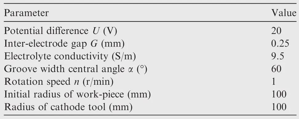
Table 1 Conditions of electric field simulation.
2.2.Principle of the SDPI method
To reduce the stray current attack and obtain better machining accuracy,a new method of site directed power interruption(SDPI)is proposed.In the SDPI process,a specific poweroff interval Toff,which is determined by the coupling relationship of the rotation speed,the radius of the work-piece Ra,and the width of the convex strip b,is used to reduce the current attack in the non-machining area,as shown in Fig.4.The anode work-piece and the cathode tool rotate relatively at the same angular velocity,while the cathode tool keeps moving towards the work-piece at a constant feed rate simultaneously,and then the convex strips on the anode work-piece could be processed gradually.In this periodic process of removing materials,the non-machined area of the work-piece surface,that is the top surface of the convex strips structure,corresponds to the Tofftime.This will greatly reduce the stray current on the top surface of the convex strips during the ECM process,especially when the convex strips rotate into the machining area.The rest area of the work-piece surface,that is the machined area,corresponds to the Tontime.The Tofftime and the Tontime constitute a power cycle time T.From this process,it can be seen that the Tofftime is the key factor for obtaining a better profile of the convex strips,which is closely related to the rotation speed,the radius of the work-piece,and the width of the convex strip.Therefore,the Tofftime should be particularly predicted and controlled.
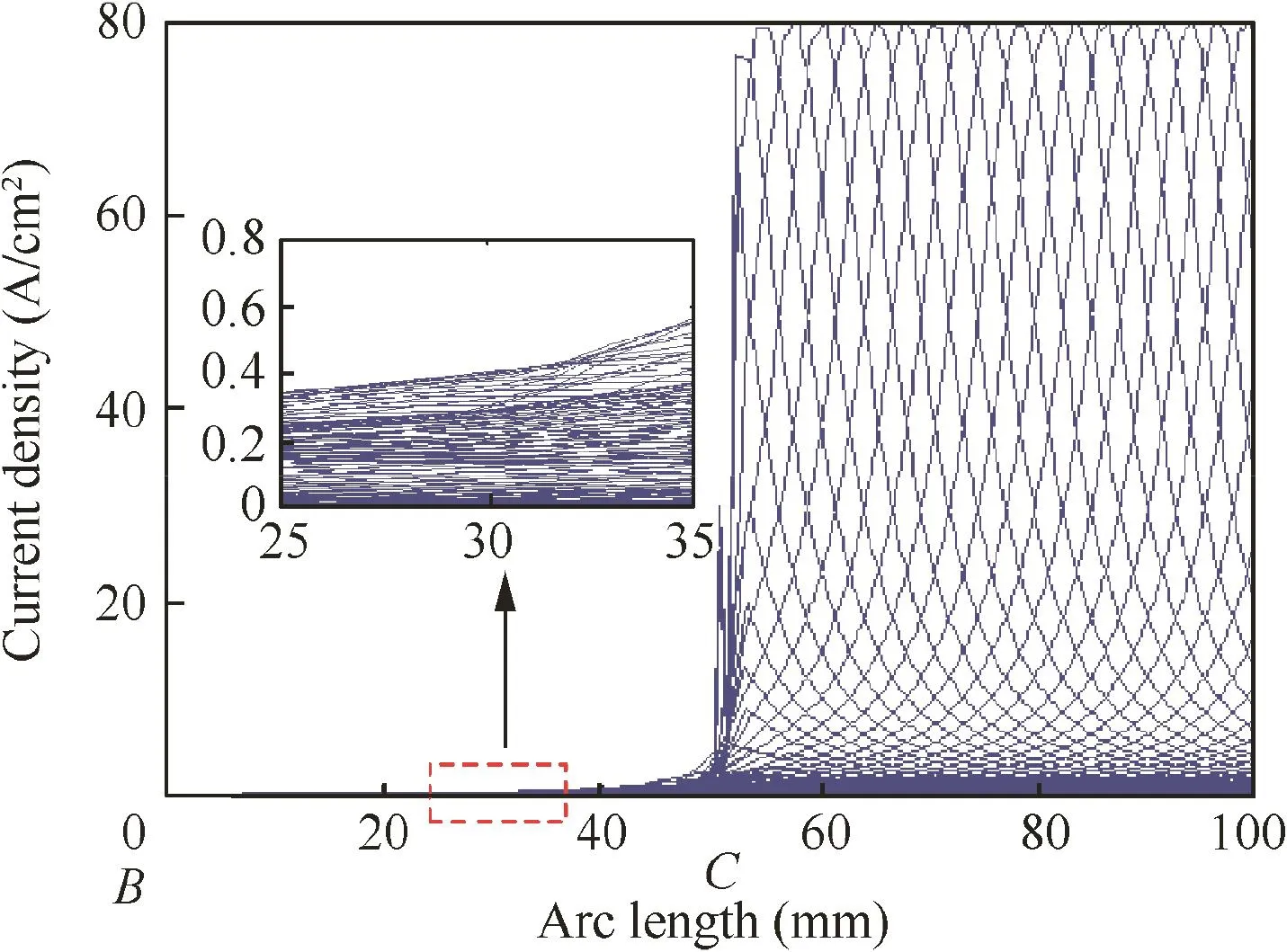
Fig.3 Current density distributions on the anode surface at different rotation angles.
According to the current density distributions on the arc length at different rotation angles shown in Fig.3,the horizontal coordinate can be converted to a variable of the machining time when the rotation speed is constant.The current density distributions at different machining times can be obtained.As shown in Fig.5,a valley region of the current density can be seen for the non-machined top surface of the convex strips.To reduce the stray currents on the surface of the convex strips,the Tofftime should correspond to the time interval in the valley region,as shown in Fig.5,and it is found that the Toffzone approximately lasts from 10 s to 20 s.According to the geometric relation of the corresponding central angle of the groove width,the Tofftime can be calculated as follows:

where α is the central angle of the groove width,and Rcis the initial radius of the cathode tool.
However,considering the influences of the anode diameter change and the stray current during the ECM process,the ideal interval Toff-idealmay be less than the interval that is illustrated in Fig.5.Therefore,a variable a,as shown in Fig.5,is defined as a correction value of the Tofftime to express the ideal interval Toff-idealas follows:

3.Numerical simulation
Numerical simulations of the electric field distribution and the formation of the convex strips have been performed to verify the proposed method.The physical model of the electric potential domain is presented in Fig.2,and the power supply operates according to the following equations:

Numerical simulations of the electric field distribution within the electrolyte domain are consistent with Section 2.1.Fig.6 shows the current density distributions of the anode surface from point B to point C during a single rotation.Each line represents the current density distribution at a different rotation angle.Fig.6(a)shows the current density distribution with a DC power.It can be seen that the current density line is relatively dense and lager.Even at point B,a stray current still exists with a maximum corrosion current density of about 0.215 A/cm2.Fig.6(b)shows the current density distribution using the SDPI method with a Tofftime of 10 s.The current density lines are reduced significantly,and the maximum corrosion current at point B is reduced to about 0.165 A/cm2.
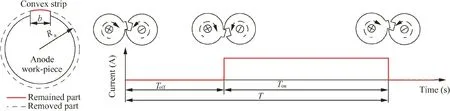
Fig.4 Principle of the SDPI method.
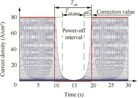
Fig.5 Ideal interval of SDPI method.
The dynamic formation process of the convex strips structure was simulated by using the finite element method.The simulation algorithm was designed and performed on the basis of the ANSYS commercial software.The cathode feed rate was set as 0.015 mm/min.The correction value of the Tofftime,a,was set as 0.4,0.6,0.8,1.2,and 1.6 s.The remaining relative conditions were the same as in Table 1.
The simulated profiles of the convex strips are presented in Fig.7.The cathode feed amounts used in this simulation was 2 mm.It is seen that the use of SDPI can effectively reduce stray corrosion on the surface of the convex strips structure.When a DC power is applied,the amount of stray corrosion can reach a remarkable value of 0.19 mm.In contrast,the amount of stray corrosion can be dramatically reduced by using SDPI.From Fig.7,it is seen that the amount of stray corrosion can reach a small value of 0.05 mm when the correction value of the Tofftime is taken as 0.6 s.

Fig.7 Change of convex height with different correction values.
Fig.8 shows the sidewall profiles of the simulated convex structure at different correction values.It is seen that the sidewall profiles for SDPI are much better than those of the DC.When a DC power is applied,large-slope edge profiles are observed.In contrast,when the SDPI method is applied,the machining accuracy of the sidewall profile is improved significantly.From the local magnification in Fig.8,it is seen that a set of distinct sharp profiles of the convex strips sidewall is obtained by using the SDPI method.
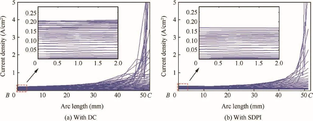
Fig.6 Current density distributions at different rotation angles.
The correction value also has an important influence on the machining accuracy.The local magnifications in Figs.7 and 8 show that the machining accuracy increases as the correction value of the Tofftime decreases,but when the correction value of the Tofftime is less than 1.2 s,the machining accuracy does not change significantly,and when the correction value of the Tofftime is less than 0.6 s,a numerical simulation will not be carried out due to the interference between the anode and the cathode.Therefore,a suitable correction value of the Tofftime is in the range of 0.6–1.2 s.
4.Experimental procedures
A revolving part with a rectangular convex strips structure was machined to verify the effect of SDPI on improved forming accuracy during the ECM process.Fig.9 shows the schematic diagram of the experimental set-up.A power is prepared to supply the machining voltage,which can freely adjust the electrical parameters in a large range.The motions of the cathode and the anode are consistent with the previous description in Section 2.1.
Combining good anti-corrosion and high mechanical properties with excellent weldability,Inconel 718 has been widely used in aviation,aerospace,petroleum,chemical,energy,and other fields.However,a previous study has shown that Inconel 718 suffers serious corrosion even at a low current density.21In these experiments,to control the stray current in the nonmachining area,Inconel 718 was used as a test piece material by using the proposed SDPI method.The initial diameter of the anode work-piece was Ø200 mm.The cathode tool for the experiments was made of SS304 with the same size as that of the anode,and a rectangular groove with a 60°central angle was fabricated on the cylinder.The sidewall and bottom face of the groove on the cathode were electrically insulated from the electrolyte by epoxy resin coating.During the electrochemical machining process,the electrolyte temperature was 30°C,the flushing pressure was 0.6 MPa,and the other experimental conditions are listed in Table 2.After machining,the test piece shape was measured by using a coordinate measuring machine and analyzed by the MATLAB software.
5.Results and discussion
Fig.10 presents the rectangular convex strips structures in three different situations.For the convex strips structure with DC power shown in Fig.10(a),it is obvious that the convex strips profile is very poor.The edge profile of the convex strips sidewall is very sloped,the height of the convex strips is maintained to a small value of 1.883 mm,and the top surface of the convex strips is an apparent electrolytic machined surface that often occurs at low current densities in ECM processing.The whole top surface of the convex strips structure is seriously corroded due to the existence of high stray currents,which accords with the simulation results shown in Fig.6(a).
Fig.10(b)shows the convex strip structure using the SDPI method with a correction value a of 1.Compared with the convex strips structures using DC power,the machining accuracy is remarkably enhanced,the edges are much sharper,and the height of the convex strips structure is maintained at 2.062 mm.In particular,from the top surface,it is seen that selective corrosion can be observed,and a large number of initial surfaces remain,which indicate that the stray current on the whole non-machined top surface is significantly reduced by using the SDPI method.This accords with the simulation results shown in Fig.6(b).Fig.10(c)shows the convex strips structure using the SDPI method with a correction value a of 0.Short circuit occurred after processing was carried out for about 20 min.This is consistent with the analysis about the correction value of the Tofftime in Section 3.
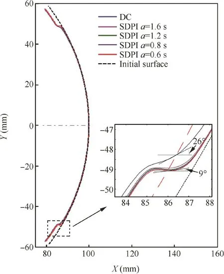
Fig.8 Sidewall profiles at different correction values.

Fig.9 Schematic diagram of experimental set-up.

Table 2 Experimental conditions.

Fig.10 Convex strips structures fabricated in different situations.

Fig.11 SEM images of machined specimens.

Fig.12 Angle between the tangents of machined profile and ideal profile.
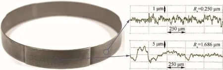
Fig.13 Photograph of machined specimen.
To further reflect the protection of the SDPI method for convex strips,the surface morphology of the top surface was measured by scanning electron microscopy(SEM).Fig.11(a)shows the surface morphology machined with DC power,and a typical ECM surface morphology is observed.In contrast,the surface morphology machined with the SDPI method shows that there are still a large number of initial surfaces on the top surface of the convex strip,which further confirms that stray corrosion on the whole non-machined top surface can be effectively reduced by using the SDPI method.
To reflect the effect of the SDPI method on the machining accuracy of the convex strips sidewall,θ is defined to describe the angle between the tangent of the machined profile and that of the ideal profile.As shown in Fig.12,h represents the height of the machined convex strip,and θ1,θ2,and θ3represent the θ values with different correction values,respectively.The angles between the tangent of the ideal profile and those of the machined profiles with DC and SDPI were measured.Results show that the angle for DC power,θDC,tends to be a much higher value of 45°.In contrast,when the SDPI method was applied,the angle of θSDPIcan be dramatically reduced to 32°.This is consistent with the simulation result of the sidewall profile in Fig.8,where the angle between the ideal profile and the simulation profiles with DC and SDPI drops from 26°to 9°.
It can be concluded therefore that the SDPI method with a suitable correction value is very effective to improve the machining accuracy of the convex strips structure during the ECM process.This method is also a promising way for machining other structures on revolving parts such as stiffener,groove,keyway,spline and gear,due to its easiness to implement and no cost to lose.
Finally,a thin-wall revolving part with a convex strip height of 2 mm was machined by using the proposed method.In this work,the correction value a was 0.9 s,and the cathode feed rate was 0.016 mm/min.The rest parameters were consistent with those in Tables 1 and 2.The total machining time was only about 2 h.The machined sample is shown in Fig.13.It is obvious that the convex profile is sharp.Compared with the traditional processing method,the proposed method not only overcomes the influences of mechanical properties of the material on processing,but also avoids deformation of the thin-walled parts.Furthermore,the machined surface is very smooth with a surface roughness of 0.250 μm.Even in the non-machining area of the top surface,the roughness reaches 1.686 μm.In traditional machining,however,the surface roughness of finished turning is only about 1 μm.
6.Conclusions
In this paper,a new method applied with site directed power interruption(SDPI)is proposed to machine a convex strips structure on a cylindrical surface in the ECM process.This method is also a promising method for machining of surface structures on a cylinder,such as stiffener,groove,keyway and spline,due to its easiness to implement and no cost to lose.Both numerical simulations and laboratory experiments were conducted to illustrate the effectiveness of the SDPI method.Conclusions can be summarized as follows:
(1)Simulation results indicated that using the SDPI method can significantly reduce the magnitudes of stray current densities on the non-machined area,and improve the machining accuracy of the convex strips structure.
(2)The correction value of the Tofftime had an important influence on the machining accuracy.A suitable correction value in the range of 0.6–1.2 s can effectively improve the machining accuracy of the convex strips structure.
(3)Experimental results also verified that the proposed method with a suitable correction value of the Tofftime could be effective to improve the machining accuracy of the convex strips structure in CRECM.
Acknowledgment
The authors wish to acknowledge the financial supports provided by the State Key Program of the National Natural Science Foundation of China(No.51535006)and Jiangsu Key Laboratory of Precision and Micro-Manufacturing Technology of China.
杂志排行

CHINESE JOURNAL OF AERONAUTICS的其它文章
- Guide for Authors
- Postcapture stabilization of space robots considering actuator failures with bounded torques
- A multi-index assessment method for evaluating coverage effectiveness of remote sensing satellite
- Integrating BDS and GPS for precise relative orbit determination of LEO formation flying
- Training effectiveness evaluation of helicopter emergency relief based on virtual simulation
- Turbulent characteristics and rotation correction of wall function in rotating channel with high local rotation parameter