Postcapture stabilization of space robots considering actuator failures with bounded torques
2018-10-15XiaokuiYUETengZHANGHonghuaDAIXinNINGJianpingYUAN
Xiaokui YUE,Teng ZHANG,Honghua DAI,Xin NING,Jianping YUAN
aNational Key Laboratory of Aerospace Flight Dynamics(AFDL),Northwestern Polytechnical University,Xi’an 710072,China
b School of Astronautics,Northwestern Polytechnical University,Xian 710072,China
cDepartment of Mechanical Engineering,University of Alberta,Edmonton T6G 2R3,Canada
KEYWORDS Actuator failure;Attitude control;Bounded torque;Postcapture;Space robot
Abstract Space robotics is regarded as one of the most impressing approaches for space debris removal missions.Due to the residual momentum of debris,it is essential to stabilize the base rapidly after capture.This paper presents a novel control strategy for stabilization of a space robot in postcapture considering actuator failures and bounded torques.In the control strategy,the motion of the manipulator is not regarded as a disturbance to the base;in contrast,it is utilized to compensate for the limitation of the control torques by means of an inverse dynamical model of the system.Different scenarios where actuators are external mechanisms or momentum exchange devices have been carried out,and for actuator failures,both single-and two-actuator failures have been considered.Regarding to the performance of actuators,control torques are bounded.In cases that either single or two actuators have failed,the base can be stabilized kinematically when actuators are external mechanisms,but can only be stabilized dynamically when only momentum exchange devices are used.Finally,a space robot with a seven-degree-of-freedom manipulator in postcapture is studied to verify the validity and feasibility of the proposed control scheme.Simulation results show that the whole system can be stabilized rapidly.
1.Introduction
The earth’s orbit is in a serious predicament caused by millions of space debris.1Fig.1 shows the number of objects in the earth’s orbit according to Ref.2.

Fig.1 Monthly number of objects in the earth’s orbit by object type in Ref.2 Credit:NASA.
According to the Kessler syndrome,collisions among debris would increase the amount of debris even if all the launches into space would be stopped immediately.3To better preserve the environment for future missions,active debris removal must be done.4The earth’s orbit is a key environment to both private and military sectors,providing services that the modern world relies upon.5Space robotics is considered as one of the most promising approaches for orbital debris removal missions.6Some missions about space robots have been successfully launched like Orbital Express7and Engineering Test Satellite VII(ETS-VII).8
Most of the threatening space debris pieces are tumbling due to their residual angular momenta.1It is essential to stabilize the system in postcapture so as to meet the expected requirements of space missions such as communication.Many works have been done for stabilizing space robots in postcapture.9–13However,in the existing studies,it is assumed that the attitude control system(ACS)works well,and a control torque can be generated along three axes for control purposes,although from different actuators.A rapid control strategy for space robots in postcapture with actuator failures has not been considered before.
Actuator failure can cause serious problems for space missions,examples including GPS BII-07,Galaxy IV,and Hubble.14For the ACS of spacecrafts,there are mainly two different kinds of actuators:one can be regarded as some external mechanisms like gas jets,while for the other,the control torque can be regarded as an internal torque,which is generated by momentum exchange devices such as reaction and momentum wheels.
Researchers have done a lot of work about attitude control of underactuated satellites.It was firstly conducted by Crouch,who provided necessary and sufficient conditions for control of a satellite in cases that thrusters could yield one,two,or three independent torques,while for momentum exchange devices,controllability was shown to be impossible with fewer than three independent actuators.15Tsiotras et al.conducted a control law for stabilizing the attitude of a nonsymmetric rigid body spacecraft with only two pairs of gas jet actuators based on the theory of differentially flat systems.16,17Kim and Turner introduced three single-axis maneuvers for a satellite with a control torque only along two axes,in which the initial and final times are fixed,but the switching time is unknown,and the nonlinear necessary conditions are solved by the multiple shooting method.18Later,they advanced their study by obtaining an optimal control strategy via a Davidenko-like homotopy algorithm and exploring the near-minimum-time control of an asymmetric rigid spacecraft with a bounded control torque.19,20Kumar and Zou conducted a control strategy for a pico-satellite with only a single thruster,and the thruster orientation mechanism was used which tilts the thrust vector on a two-axis gimbal.21
When spacecraft attitude control is obtained by exploiting internal torques generated by momentum exchange devices,gyroscopic coupling makes the issue of underactuated attitude control even more difficult.22With only one single-gimbal variable-speed control moment gyro(VSCMG),Yoon and Tsiotras utilized a feedback control law to achieve the control of a body- fixed line-of-sight,and a multi-stage control law was used to achieve the control objective in different situations.23In Ref.14,to stabilize the attitude of an underactuated satellite under the assumption of zero momentum,two control strategies were conducted.The first one that is based on a perfect zero momentum does not need to measure the angular velocity,and it has been verified by in-orbit satellites,while the second tracks the desired angular velocity.Gui et al.studied attitude tracking ofa rigid spacecraftby using two momentum-exchange actuators like reaction or momentum wheels.24
However,there are few papers about stabilization of space robots considering actuator failures in postcapture.Based on the immersion and invariance method,Sarras et al.designed a control strategy for stabilization of mechanical systems with an under-actuation degree larger than one.25For space robots,the moment of inertia with respect to the mass center would vary dramatically after capturing space debris,and often a system has an initial angular momentum due to the residual momentum of debris.These issues make the traditional control strategy unstable or even invalid.
For a space robot,motions of the base and the manipulator are strongly coupled.Dragomir et al.have conducted null reaction space control(NRSC)for planning the motion of the manipulator which causes a minimal disturbance to the attitude of the base.26NRSC has been verified by the flight experiment of ETS-VII,and has been applied to other un fixed-base systems,e.g., flexible-base and macro/mini robot systems,as well as humanoid robots.27,28Based on NRSC,some works have been done for further development.Wang et al.planned the motion of the manipulator to finish multiple missions which caused a minimal disturbance to the attitude of a free- floating space robot.29Nguyen-Huynh and Sharf designed a recursive adaptive controller for stabilizing the base after capturing a tumbling target.30However,NRSC is based on the kinematic equation of space robots,so a control torque cannot be utilized,and the manipulator should move all the time to stabilize the base for a system with momentum.
Attributed to the coupling between the motions of the manipulator and the base,Zhang et al.have conducted a control strategy which utilizes both a control torque and the motion of the manipulator for stabilizing the base rapidly,and the whole system,including the base and the manipulator,can be stabilized finally.31The limitations of the previous study are twofold:(i)only a two-dimensional model has been considered,and(ii)the actuator failure has not been considered.In this paper,the control strategy for a three-dimension(3-D)model is proposed.Consequently,the embedding technique is used to obtain the dynamics of an underactuated space robot whose actuators are momentum exchange devices,and then attitude stabilization of the base in situations where a control torque is generated along one or two axes can be achieved.When external mechanisms are actuators,the objective is to make the base maneuver to the desired attitude and stabilize the base kinematically,while for momentum exchange devices,the objective is to reduce the angular velocities of the base and stabilize the base dynamically.
It is assumed that the base is at the desired attitude but with a disturbed angular velocity at the beginning.For external mechanisms,gas jet thrusters are analyzed as an example,while for momentum exchange devices,momentum wheels are used.Two situations have been analyzed.In situation I,the control torque can balance the angular momentum of the system at the desired attitude,and thus the base is able to maneuver to the desired attitudefinally including scenarios where gas jet thrusters or momentum wheels are actuators.For situation II,the base cannot approach to the desired attitudefinally if momentum wheels are actuators.The control strategies for the control torque along one or two axes are both conducted.In the case of a single-actuator failure,it is assumed that the control torque can be produced along the x-axis and y-axis of the body frame of the base,while for the case of a two-actuator failure,the control torque can be generated only along the x-axis.The orbital dynamics is neglected here,the 1–2–3 Euler angle sequence is used for describing the attitude of the base,and the actuator failure is known.

Fig.2 General space robot.
The contents of this paper are organized as follows.In Section 2,a dynamical model for a multibody system based on the recursive method and the system with constraints via the embedding technique are firstly introduced.Then a control strategy which utilizes a control torque and the motion of the manipulator is proposed in Section 3.In Section 4,a control scheme with gas jet thrusters as actuators is conducted,and scenarios where momentum wheels are actuators are analyzed in the next section.Numerical simulations are carried out to validate the presented control strategies in Section 6.Finally,conclusions are drawn in Section 7.
2.Dynamics
2.1.Recursive method
The general model of a space robot is showed in Fig.2.The manipulator is made up of an arm and an end-effector.
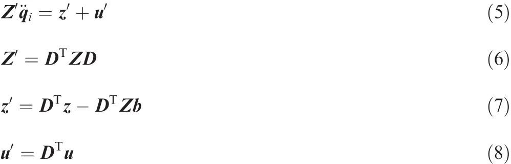
There are variety of methods for multibody system dynamics.In this paper,the recursive way conducted by Wittenburg is used.32Compared with analytical methods like the Lagrangian Method,the recursive method offers a possibility to do the calculation for systems with many degrees-of-freedom(DOFs),while analytical methods reach their limits.33According to Ref.32,the dynamic equation can be written as:

where Z is the generalized mass matrix,z is the generalized force array,is the second-derivation with respect to time of the generalized coordinates q,and u is the vector of the control force of the joints.
It is assumed that only the base is equipped with an ACS.For momentum wheels,the control torque is the internal torque;the mass of momentum wheels is ignored,and only the moment of inertia along the rotation axis is considered for simplification.On the contrary,for gas jet thrusters,the control torque is regarded as the external torque,but it is body- fixed to the base.
2.2.Embedding technique
To obtain a dynamical model of the system with constraints,generally there are two ways,augmented equation and embedding technique.34In this study,the embedding technique is utilized.For holonomic constraints,the constraint equations can be written as:

where C=[C1(q,t), C2(q,t), ···, Cnc(q,t)]Tis the vector of constraint functions,in which ncis the number of constrain functions,and t is the time.
Deriving Eq.(2)with respect to time twice,it can be written as:

With the help of Eq.(3),the generalized coordinates q can be written by separating terms with the independent ones qiand the dependent ones qd,where
The second-order derivations of the dependent coordinatescan be written as the linear functions of the second-order derivations of the independent ones,so the second-order derivations of the generalized coordinatescan be described as the linear function of,which can be written as:

where D and b are decided by Eq.(3).
Putting Eq.(4)into Eq.(1)and pre-multiplying DT,the dynamic equation for the system with constraints can be written as:
where Z′is the generalized mass matrix;z′is the generalized force array;iis the second-derivation with respect to time of the generalized coordinates qi;u′is the array of the control force of the joints for the system with constraints.For u′,some properties are shown next.These properties are essential to gain a control strategy in following parts.
For a space robot,suppose that there are n joints and there is no control torque on the ith joint,which means that the angular acceleration of the ith joint can be written as a function of the other joints.The matrix D can be written as:
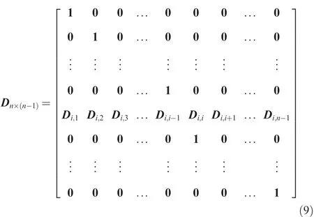
where 1 is a unit matrix and 0 is a zero matrix.The dimension of element Dm,lis δm× δl,in which δmrefers to the degree of freedom of the mth independent joint.Then u′can be written as:

In this study,for a wheel which cannot work,there is no control torque,which means that ui≡0.Then according to Eq.(10),=u1.
3.Control strategy
According to Ref.31,the motion of the manipulator can be utilized to compensate for the limitation of the control torque,and authors have done further research.A control strategy is introduced in this section.
3.1.Control scheme
From Eq.(5),the inverse dynamical model of the system with constraints can be written as:(only one constraint equation is considered here)
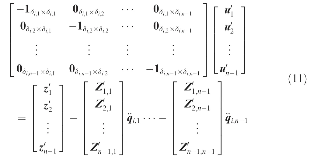
where 1 is a unit matrix while 0 is a zero matrix,and
Joint 1 is the virtual joint between the base and the inertial frame,and the control torque u1could be regarded as the external force and torque to the base,which can be included in the generalized force array,so u1≡0.Then by combining Eq.(10)with Eq.(11),the following equation can be obtained:

On the right side of Eq.(12),ifi,jis known,which means that it is a dependent joint,the relevant column should be moved to the left side,and then Eq.(12)can be written as:

where x refers to the angular accelerations of the independent joints,and the solution of Eq.(13)can be written as:

where H+refers to the pseudo inverse matrix of H,E is a unit matrix,and ξ is an arbitrary vector with units of angular accelerations.
3.2.Control law for stabilizing the base
It is assumed that the max angular acceleration of Euler angles is bounded,and the work for finding the minimal time control law is shown here.The general control problem of minimal time consumption can be described as:
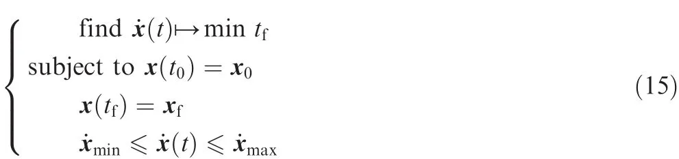
Here,subscripts 0 and f refer to the initial and final values,respectively,for example,t0and tfare the initial and final time,respectively.x means the state vector,which has different physical meanings in different situations.According to Ref.20,the minimal time control problem can be easily solved via Pontryagin’s minimum principle.
4.Gas jet thrusters
For the ACS of space robots,there are generally two different kinds of actuators,external mechanisms like gas jet thrusters and momentum exchange devices like reaction or momentum wheels.Their difference would make the control strategy different.Scenarios where gas jet thrusters are utilized as actuators are introduced firstly.
4.1.Control strategy
The control torque from thrusters can be regarded as an external torque to a robot,but it is body- fixed,which can be written as:

where Abodyis the direction cosine matrix of the base,in which subscript body refers to the body frame of the base,while superscript in refers to the inertial frame and is often neglected,and Mbodyis the control torque.For thrusters,suppose that Mjetis the constant thrust level,and the control torque is only Mjetor-Mjet.
In the control strategy,the control torque is only used for balancing the angular momentum.However,it cannot be utilized to balance the momentum at the desired attitude directly in some situations considering actuator failure.Then the designed attitude qdes,at which the control torque can balance the momentum,is defined.At the designed attitude,the control torque is parallel to the momentum but with an opposite direction in the inertial frame.With the help of Eq.(16),the corresponding direction cosine matrix as well as Euler angles of the designed attitude can be computed.The control strategy consists of two parts,one for the base and one for the manipulator,so they are discussed separately.
4.2.Situation I
In this situation,the control torque from the ACS can be used to balance the angular momentum P at the desired attitude according to Eq.(16).This means that the following constraints must be satisfied:
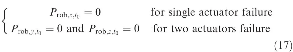
where subscript rob means the whole space robot,while subscript y or z means the y-or z-axis.For example,Prob,y,t0and Prob,z,t0mean the angular momentum of the whole space robot in the y-and z-axis of the inertial frame at the initial time,respectively.The thrusters begin to work when the base maneuvers to the desired attitude with a null angular velocity,and they would stop when the momentum of the robot becomes zero.For the base,its attitude would maneuver to the desired value and then stay at it according to the results from Eqs.(12)–(15).For the manipulator,since the motion of the base is known,Eq.(12)can be utilized to get the motion of the manipulator;all the joints are independent joints at the beginning,and then the motions of some joints are designed which means that they become dependent,so this change would stop the manipulator with the special motion of the base considering the redundancy of the manipulator.In this situation,the transient time includes two parts,the time consumption for stabilizing the base and balancing the momentum by the thrusters.
4.3.Situation II
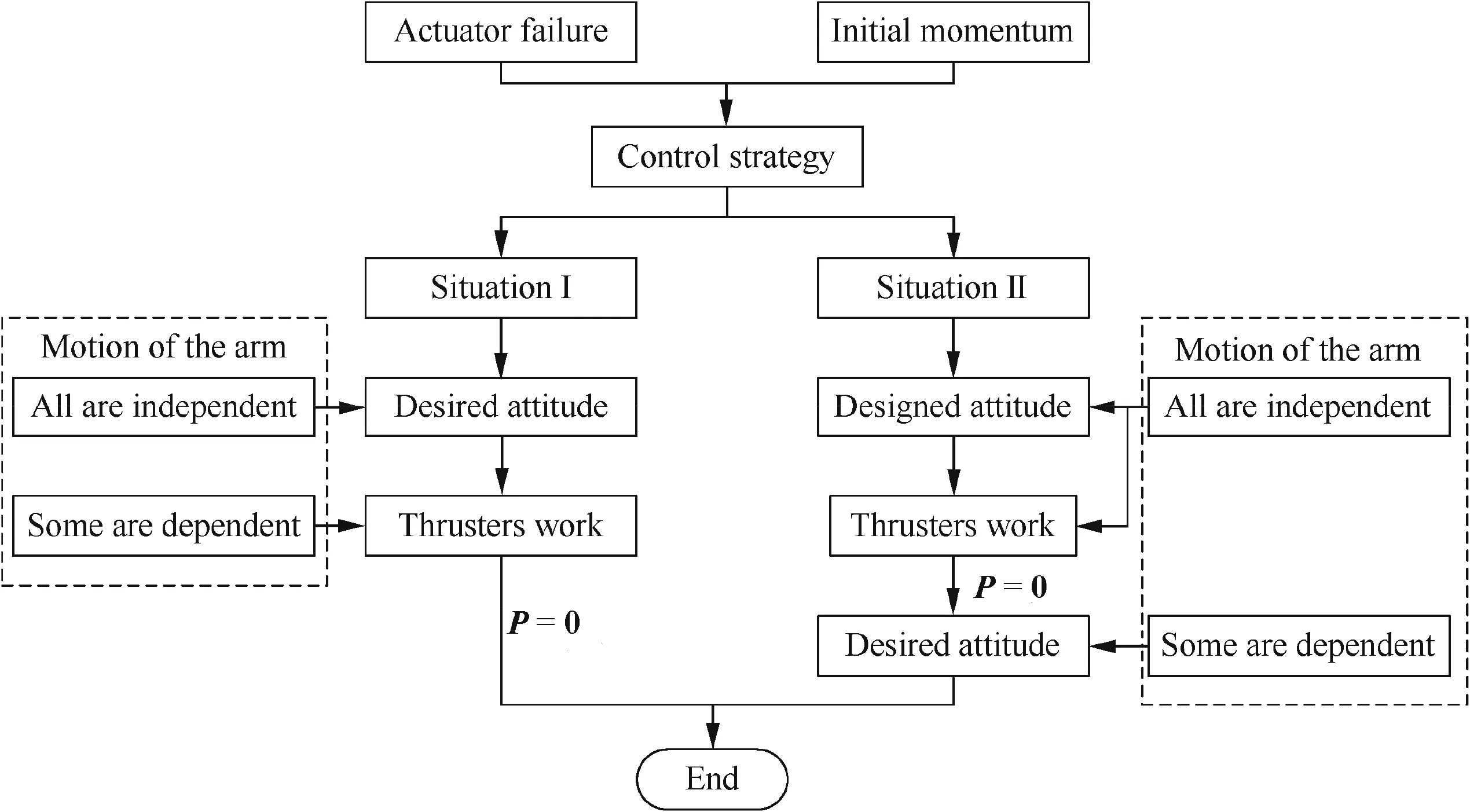
Fig.3 Implementation of the control strategy when jet thrusters are actuators.
In this situation,due to the limitations of the control torque,mainly the direction,it cannot be utilized to balance the momentum at the desired attitude,which means that the momentum of the system does not satisfy Eq.(17),so the control strategy is different,and the base must maneuver to the designed attitude for stabilization.For the base,the motion of attitude includes three stages.At first,the base maneuvers to the designed attitude,and then stays at it;meanwhile,the thrusters begin to work.When the momentum of the robot becomes zero,the base would maneuver to the desired attitude and stay at it,while for the manipulator,all the joints are independent at first,and then for stopping the manipulator,the motions of some joints are designed.In this situation,since the motion of the base includes three stages,the transient time would be the sum of them all.When gas jet thrusters are actuators,the corresponding flow chart is shown in Fig.3.
5.Momentum wheels
For a space robot whose actuators are momentum wheels,since disturbances are not considered here,the total angular momentum of the whole system Psys,t,including the robot Prob,tand the momentum wheels Pwhe,t,is conserved(both in magnitude and direction),which can be written as:

where subscripts whe and sys represent the momentum wheels and the whole system,respectively.
Conservation of the momentum makes the control strategy different.Finally,the momentum of the robot is zero,and according to Eq.(18),the base as well as the arm does not move.When the final state of the wheels is known,the motion of the wheels can be obtained if the acceleration of the wheels is clear.Therefore,the following work is done for obtaining the final momentum of the wheels with different actuator failures.When the motions of the wheels and the base are known,the second-order derivations of their coordinates are known,so the corresponding column in the bottom parts of Eq.(12)can be moved to the upper parts,and only the motion of the arm is unknown.The following work is done for obtaining the final states of the base and the wheels to which the base is the closest at the desired attitude.The magnitude of the control torque from wheels is much smaller than that from thrusters,and it takes much more time to balance the momentum;thus the transient time would be decided by the acceleration of the wheels.
5.1.Control strategy
When momentum wheels are actuators only,there is a momentum exchange between the wheels and the space robot when the wheels change the angular velocity.Finally,the base as well as links of the manipulator has a null angular velocity,which means that the momentum of the whole robot becomes zero.Then according to Eq.(18),the following equation must be satisfied finally:

The wheels are body- fixed to the base,so the momentum of the wheels in the inertial frame can be written as:

To analyze the coupling between the wheels and the base,it is assumed that the initial angular velocity for the three-axis wheels relative to the base is 100 r/min,no matter they work well or not.
5.2.Situation I
In this situation,the attitude of the base would be the desired value finally,which means that the momentum of the robot after capture satisfies Eq.(17).Therefore,the control strategy in this part is the same as that in situation I where thrusters are actuators.However,the magnitude of the control torque from wheels is much lower than that from thrusters,and the transient time is much longer.
5.3.Situation II
In this situation,the base cannot approach to the desired attitude when it does not rotate,which means that the angular momentum of the robot in postcapture does not satisfy Eq.(17),and then it is essential to investigate the feasible final orientations of the base which do not violate the law of momentum conservation,among which, find the one that is the closest to the desired values.
Considering conservation of the momentum,it firstly should be mentioned that the magnitude is equivalent which can be written as:

where‖a‖means the norm of vector a.
For a wheel which cannot work,it is assumed that there is no control torque along its rotation axis,so the magnitude of its angular velocity as well as the angular momentum along the rotation axis would not vary with time.
In the case of a single-actuator failure,two wheels can be controlled.According to Eqs.(19)and(21),the magnitude of these two wheels at the final time meets the following demands:

The angular momentum of the two controlled wheels can be computed via Eq.(22).Next,the work for finding the feasible orientation which is the closest to the desired one will be done.To achieve it,the definition of quaternion is used.For a rigid body,any arbitrary rotation could be regarded as a rotation of angle θ along the rotation axis,and then the direction cosine matrix can be written as:

where λ0=cos(θ/2), λ1=l1sin(θ/2), λ2=l2sin(θ/2),and λ3=l3sin(θ/2);l= [l1,l2,l3]Tis the unit vector of the rotation axis,and θ is the rotation angle.
Suppose two vectors a and b with the same magnitude,and then b could be obtained from a with only one rotation.The unite vector of the rotation axis l and the rotation angle θ could be computed as:
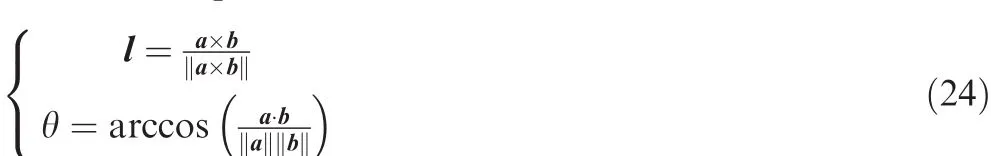
Then the corresponding direction cosine matrix can be obtained via Eq.(23),as well as the Euler angles.Next,the work for finding the feasible orientation which is the closest to the desired one is done.Suppose that the base is fixed at the initial orientation at the beginning,and the momentum of the controlled wheels satisfies Eq.(22);then for the direction,it would be achieved via a rotation of the base from Eqs.(20)and(23).The problem can be described as to find the momentum of the wheels Pwhe,minimal,which meets the following demands:

After Pwhe,minimalis known,the corresponding direction cosine matrix and the Euler angles qmincan be computed via Eqs.(23)and(24).
In the case of a two-actuator failure,only one wheel can be controlled.According to Eqs.(19)and(21),the magnitude of the angular momentum of the wheel meets the following demand:

According to Eq.(26),there are only two different states for the controlled wheel finally,which means that there are only two feasible orientations.The corresponding Euler angles can be computed via Eqs.(23)and(24),and then the work for finding the one which is closer to the desired value can be done.The flow chart for the control strategy when momentum wheels are actuators is shown in Fig.4.
6.Simulation
To validate the control strategies in this study,numerical simulation for different situations has been carried out.Since only stabilization in postcapture is considered,the contact dynamics for capturing a target is ignored here,and all the parameters of the system are known.The simulation model is shown in Fig.5.
Suppose that the end-effector of the space robot grasps the target firmly,and there is no relative motion between them,which means that these two bodies can be simplified into one.The parameters of the robot and the target are shown in Table 1.All these parameters are calculated in the CAD software Solidworks®with certain geometric dimension and density.
The simulation is on a C language platform,and the four order Runge-Kutta numerical integration method is utilized with a step of 10-2s.Different scenarios where actuators are thrusters or wheels have been carried out,and for actuator failures,both single-and two-actuator failures have been considered.The motion of the base is decided by the momentum and actuator failure,and different typical situations are shown.It is assumed that all the joints of the manipulator are locked at first,and the limitation of motion of the joints is not considered.The magnitude of the control torque from thrusters is 1 Nm,while for momentum wheels,it is 0.1 N˙sm,and its moment of inertia along the rotation axis is 1.25 kg˙sm.2For the limitation of actuators,only actuator failure and bounded torque are considered.
6.1.Control strategy
The strategy for stabilizing the base with the minimal time consumption can be obtained via Eq.(15)when the max angular acceleration of Euler angles is bounded.To reduce the calculation error of numerical integration,the feedback control law based on the nonlinear decoupling method in Ref.31 is utilized at the end of each stage to improve the performance of the controller.

Fig.4 Implementation of the control strategy when momentum wheels are actuators.

Fig.5 Simulation model.
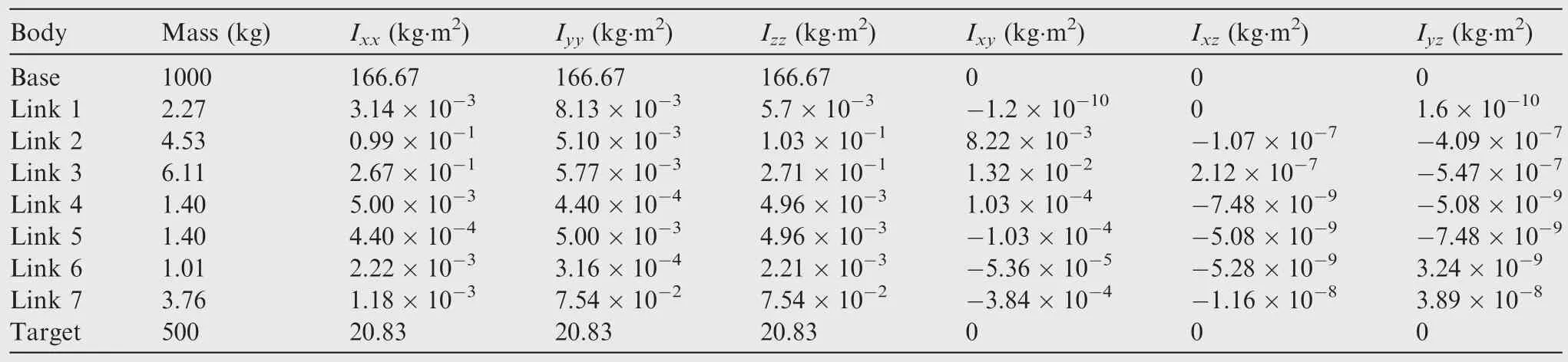
Table 1 Parameters of the model.
For the manipulator,the control strategy includes two stages.At first,all the joints of the manipulator are independent,while at the second one,the motions of joints 3,4,6,and 7 are designed for stopping the manipulator.The reasons for choosing joints 1,2,and 5 at the second stage as independent joints are that the attitude of the base has three DOFs in 3-D,and the rotation axes of these three joints are not parallel to each other.However,at the second stage,the angular accelerations of these independent joints may be too large,and then the control strategy would transform into the first one.In simulation,it is assumed that if the norm of the acceleration of the independent joints is larger than 3.14 rad˙ss-2,then the control strategy transforms into the first stage;otherwise,it is still at the second stage,which is:
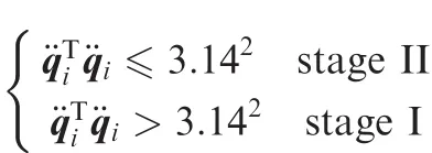
For the control strategy in Eq.(14),ξ is arbitrary,and for simplification,ξ is a zero vector all the time.The transient time for a system which uses wheels as actuators is much longer,the control strategy for the manipulator at the second stage is different,and the angular acceleration of the dependent joints can be described as:
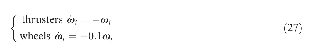
where i=3,4,6 or 7,which would make these four joints stop and stabilize the whole robot due to the null angular momentum of the whole robot finally.
6.2.Gas jet thrusters
When gas jet thrusters are actuators,the control objective is a rapid stabilization of the whole robot,and the base can maneuver to the desired attitude finally in both situations I and II.It is assumed that=5×10⁻³rad·s-2,and for the feedback controller, KP=diag(1,1,1) and KD=diag(2,2,2).The results of different scenarios are shown next.
6.2.1.Single-actuator failure
In this case,control torques can be produced along the x-axis and y-axis of the body frame of the base.Suppose that the initial angular momentum of the system is Prob,t0=[20,20,0]Tkg ·m2·s-1for situation I and Prob,t0=[20,20,10]Tkg ·m2·s-1for situation II.With the assumption that all the joints are locked at first,the initial angular velocities of the base are ωt0= [0.010,0.032,0.019]Trad/s and ωt0= [0.00068,0.050,0.053]Trad/s for situations I and II,respectively.
In situation I,the time consumption for the stabilization of the base is 15.21 s.To improve the performance of the controller,the thrusters would begin to work at 16.00 s and stop until 36.00 s with the control torque Mbody=[-1,-1,0]TN ·m in the body frame,and the switching time for the manipulator is 30.00 s.

Fig.6 Attitude of the base,when actuators are thrusters with a single-actuator failure.
Fig.7 Motions of joints,when actuators are thrusters with a single-actuator failure for situation I.

Fig.8 Motions of joints,when actuators are thrusters with a single-actuator failure for situation II.
In situation II,the designed attitude for balancing the momentum is qdes= [0.24,-0.24,0.029]Trad according to Eq.(16).For the attitude of the base,the ideal time consumption for the three stages is 29.92 s,21.21 s,and 14.00 s,respectively.Due to the existence of the feedback controller,the time consumption of stage I would increases to 30.00 s,and the two thrusters would work in the time interval t∈ [30.00,51.21]s with the control torque Mbody= [-1,-1,0]TN ·m in the body frame.For the manipulator,the switching time is 52.00 s,and simulation results are shown in Figs.6–8.
From the results in Figs.6–8,it can be seen that the whole robot including the base and the manipulator can be stabilized finally,and the base can maneuver to the desired attitude.The transient times of these two situations are 33.00 s and 65.30 s,respectively,which are equivalent to that of the control strategy.The feedback controller can improve the performance of the controller,but it would cost more time.It takes about 15.21 s and 65.30 s for the base to maneuver to the desired attitude with a null angular velocity for situations I and II,respectively.In situation I,it spends less time for the base to maneuver to the desired attitude than that of the stabilization of the whole robot.This phenomenon comes from the fact that the thrusters can work at the desired attitude regarding to actuator failures.
6.2.2.Two-actuator failure
In this part,only a control torque along the x-axis of the body frame of the base can be produced.The difference between actuator failures makes the initial momentum different.For situation I,the initial angular momentum of the robot is Prob,t0= [20,0,0]Tkg ·m2·s-1, while for situation II,Prob,t0= [20,10,10]Tkg ·m2·s-1.Then the initial angular velocities of the base are ωt0= [0.024,-0.014,-0.019]Trad/s and ωt0= [0.0078,0.028,0.034]Trad/s for situations I and II,respectively.
In situation I,the time consumption for stabilizing the base is 11.71 s,and the thrusters would work between 13.00 s and 33.00 s with the control torque Mbody= [-1,0,0]TN ·m.For the manipulator,it would change into the second stage at 23.00 s. In situation II, the designed attitude is qdes= [0.10,-0.42,0.46]Trad according to Eq.(16).For the base,the time consumptions of the three stages are 25.44 s,24.49 s,and 19.26 s,respectively.Due to the same reasons before,the thruster would begin to work at 27.00 s,and it would work for 24.49 s with Mbody= [-1,0,0]TN ·m.For the manipulator,the switching time is 52.00 s,and simulation results are shown in Figs.9–11.
As illustrated in Figs.9–11,the whole system can be stabilized finally,and the transient times for these two situations are 33.00 s and 70.76 s,respectively.Thanks to the motion of the manipulator,the whole system can be stabilized with only one torque.In situation I,the base maneuvers to the desired attitude with a null angular velocity at 11.71 s,which means that the base can be stabilized rapidly.However,in situation II,the base must maneuver to the designed attitude for balancing the momentum due to the actuator failure,which prolongs the transient time.
6.3.Momentum wheels
Momentum wheels are momentum exchange mechanisms,which makes the control scheme different.The magnitude of the control torque from a wheel is much smaller,and thus it would take much longer time to stabilize the whole robot.It is assumed thatmax=2×10⁻³rad·s-2,and for the feedback controller, Kp=diag(0.0025,0.0025,0.0025) and KD=diag(0.1,0.1,0.1).
6.3.1.Single-actuator failure
In the case of a single-actuator failure,the momentum of the robot except for the wheels is Prob,t0= [20,20,0]Tkg ·m2·s-1for situation I and Prob,t0= [20,20,10]Tkg ·m2·s-1for situation II,which are the same as before.However,due to the conservation of the momentum,the base can only be stabilized dynamically,and only in situation I,it can maneuver to the desired attitudefinally.
In situation I,the two controlled wheels would accelerate for 20.00 s with an angular acceleration of 1.25 rad˙ss-2,and a different control scheme for the base would not have an influence on planning the motions of these two wheels,because they are momentum exchange mechanisms.For the manipulator,switching happens at 60.00 s.
In situation II,due to the existence of Prob,z,t0,the base cannot approach to the desired attitudefinally,and according to Eq.(25),the corresponding Euler angles of the base which are the closest to the desired values are qmin= [0.23,-0.23,0.027]Trad.Finally,the angular momentum of the wheels in the body frame is:

The wheels need to accelerate for 213.57 s and 213.58 s with an angular acceleration of 1.25 rad˙ss-2,respectively.The switching time of the manipulator is 60.00 s,and results are illustrated in Figs.12–14.

Fig.9 Attitude of the base,when actuators are thrusters with a two-actuator failure.
Fig.10 Motions of joints,when actuators are thrusters with a two-actuator failure for situation I.

Fig.11 Motions of joints,when actuators are thrusters with a two-actuator failure for situation II.

Fig.12 Attitude of the base,when actuators are wheels with a single-actuator failure.
From the results illustrated in Figs.12–14,it can be seen that the base and the manipulator can be stabilized finally,which means that the momentum of the whole robot is absorbed by the wheels finally.The transient times for situations I and II are 200.00 s and 213.58 s,respectively,and it takes the base only 38.03 s and 66.76 s to maneuver to the final attitude.However,due to the properties of the wheels and the actuator failure,the base cannot approach to the desired attitude in situation II,which corresponds to the work before.As shown in Figs.13 and 14,for the manipulator,the control strategy at the second stage would change into the first sometimes,and this phenomenon comes from the fact that the angular accelerations of the independent joints are too fast,so the strategy changes.

Fig.13 Motions of joints,when actuators are wheels with a single-actuator failure for situation I.
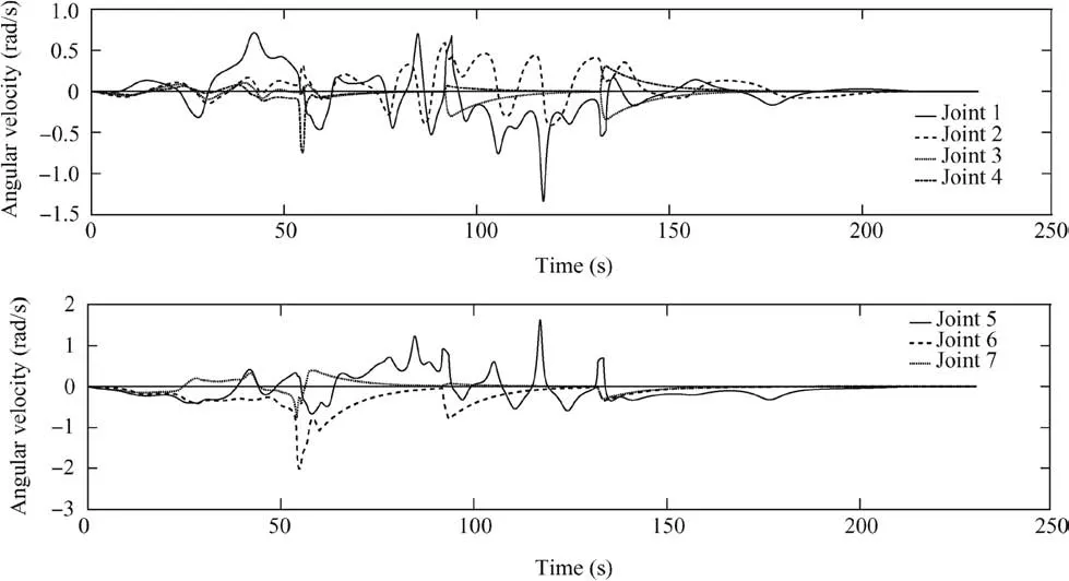
Fig.14 Motions of joints,when actuators are wheels with a single-actuator failure for situation II.
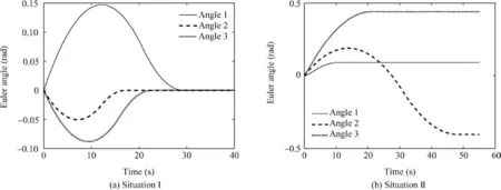
Fig.15 Attitude of the base,when actuators are wheels with a two-actuator failure.
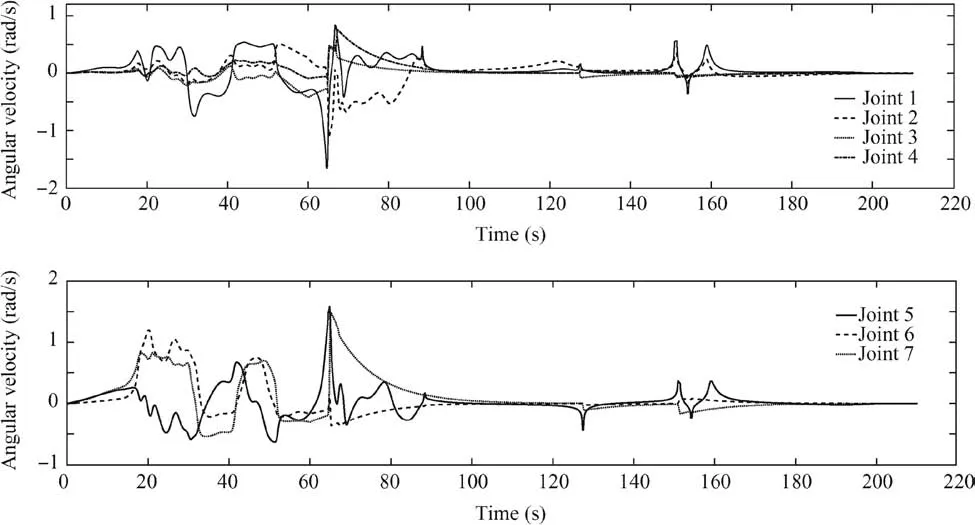
Fig.16 Motions of joints,when actuators are wheels with a two-actuator failure for situation I.

Fig.17 Motions of joints,when actuators are wheels with a two-actuator failure for situation II.
6.3.2.Two-actuator failure
In the case of a two-actuator failure,the controlled momentum wheel rotates only along the x-axis of the body frame,and the initialangular momenta of the robot are Prob,t0= [20,0,0]Tkg ·m2·s-1and Prob,t0= [20,10,10]Tkg ·m2·s-1for situations I and II,respectively.In situation I,the base can maneuver to the desired attitude,and it would take about 29.28 s for the base to be stabilized.For the wheel,it would accelerate 200.00 s with an angular acceleration of 1.25 rad˙ss-2for balancing the momentum.
For situation II,according to Eqs.(25)and(26),the momentum of the controlled wheel at final is:

The wheel would accelerate for 250.04 s with an angular acceleration of 1.25 rad˙ss-2.The attitude of the base is qmin= [0.092,-0.40,0.44]Trad finally according to Eq.(20),and it would take the base 48.23 s to maneuver to it.Results are shown in Figs.15–17.
From the results in Figs.15–17,all the joints of the manipulator as well as the base have a null angular velocity finally,which means that the momentum of the whole robot is zero.This phenomenon comes from the fact that there is a momentum exchange between the robot and the wheel.The transient times of the whole robot are 200.00 s and 250.04 s,but the base can be stabilized rapidly,and it would take only 29.28 s and 48.23 s,which correspond to the solution of Eq.(15).The base has a null angular velocity finally,but it cannot approach to the desired attitude in situation II,which shows that it is only stabilized dynamically.
7.Conclusions
(1)Attributed to the coupling between the base and the manipulator,a novel control strategy for stabilizing a space robot with actuator failures and bounded torques in post capture has been conducted.The base can be stabilized rapidly for both single-and two-actuator failures.
(2)When external mechanisms are actuators,the base could maneuver to the desired attitude,but it can only be stabilized dynamically,if only momentum exchange wheels are used.The magnitude of the control torque from momentum wheels is much smaller than that from jet thrusters,which makes the transient time of stabilization much longer.For thrusters,control torques are used only for balancing the angular momentum,and thus energy can be saved,which may prolong the lifecycle of the space robot.
(3)Different situations have been simulated with bounded torques and max angular accelerations.The differences in actuators,actuator failures,the momentum of the system,and the initial and final states of the base make the control strategy different.Results have shown that the whole system can be stabilized finally,and the base can be stabilized rapidly with a minimal time consumption.
Acknowledgments
This paper was co-supported by the National Natural Science Foundation of China(Nos.11402200 and 11502203),and the China Scholarship Council(CSC).
杂志排行

CHINESE JOURNAL OF AERONAUTICS的其它文章
- Guide for Authors
- Electrochemical machining of a convex strips structure on a revolving part by using site directed power interruption
- A multi-index assessment method for evaluating coverage effectiveness of remote sensing satellite
- Integrating BDS and GPS for precise relative orbit determination of LEO formation flying
- Training effectiveness evaluation of helicopter emergency relief based on virtual simulation
- Turbulent characteristics and rotation correction of wall function in rotating channel with high local rotation parameter