Photometric stereo for strong specular highlights
2018-05-11MaryamKhanianAliSharifiBoroujerdiandMichaelBreu
Maryam Khanian(),Ali Sharifi Boroujerdi,and Michael Breuß
The Author(s)2017.This article is published with open access at Springerlink.com
1 Introduction
1.1 Background
Reconstruction of three dimensional (3D)information from 2D images is a classic problem in computer vision. Many approaches exist,as documented by a rich literature and a number of excellent monographs,among which are Refs.[1–3].The survey in Ref.[4]concerns 3D reconstruction methods that are more oriented towards the computer graphics community.Following Ref.[3],one may distinguish approaches based on the point spread function as in depth from focus or defocus[5],triangulation-based methods such as stereo vision[6]or structure from motion[7],and intensity-based or photometric methods such as shape from shading and photometric stereo[1]. Generally speaking,specific approaches may be distinguished by the type of image data,the number of acquired input images,and whether the camera or objects in the scene are moving or not.For example,techniques based on specular fl ow[8–10]rely on relative motion between a specular object and its environment.
Focusing on photometric approaches,as explained by Woodham [11]and Ihrke et al.[4],these typically employ a static view point and variations in illumination to obtain the 3D structure.While shape from shading is a photometric technique classically making use of just one input image[1],photometric stereo(PS)allows reconstruction of a depth map of a static scene from several input images taken from a fixed view point under different illumination conditions.Woodham pioneered PS in 1978[11],and further developments were due to Horn et al.[12].Woodham derived the underlying image irradiance equation as a relation between the image intensity and the reflectance map.It has been shown that for a Lambertian surface,orientation can be uniquely determined from the resulting appearance variations provided by at least three input images illuminated by single known,non-coplanar light sources[13].
As it is for instance also recognized in Ref.[4],most of the later approaches have followed Woodham’s idea and kept two simplifying assumptions.Of particular importance,the first one supposes that the surface reflects the light according to Lambert’s law[14].This simple reflectance model can still be a reasonable assumption on certain types of materials,when the scene is composed of matte surfaces,but fails for shiny objects concentrating light distributions. Such surfaces can readily be seen in real world situations.It is quite well proved that a light source illuminating a rough surface,reflects a significant part of the light as described by a non-Lambertian reflectance model[15–17].In such models,the intensity of reflected light depends not only on the light direction but also on the viewing angle,and the light is reflected in a mirrorlike way accompanied by a specular lobe. The second assumption in classic PS models is that scene points are projected orthographically during the photographic process. This is a reasonable assumption if objects are far away from the camera,but not if they are close in which the perspective effects grow to be important.The importance of using the perspective projection in such a situation has been demonstrated in the computer vision literature;in the context of photometric methods,let us refer for instance to the work Ref.[18]where a corresponding example is discussed in detail.
Many studies in PS consider non-Lambertian effects as outliers and try to remove them.Mukaigawa et al.[19]suggested a random sample consensus-based approach where only diffuse reflection is selected from candidates.Mallick et al.[20]introduced a rotation transformation for transforming RGB color space into an SUV color space with a specular channel S and diffuse channels UV.The specular channel S is then used to remove specularities.Yu et al.[21]introduced a strategy based on a maximum feasible subsystem approach.In their method,the maximum subset of images satisfying the Lambertian constraint is obtained amongst a whole set of PS images that include non-Lambertian effects like specularities.A median filtering technique is used by Miyazaki et al.[22]to evade the influence of specular reflections considered as outliers.Another method relying on this concept is presented by Tang et al.[23],who proposed use of a coupled Markov random field to treat the specularities and shadows as noise.Wu et al.[24]considered the 3D recovery problem using a convex optimization technique to separate specularities as deviations from the basic Lambertian assumption,defined in the objective function.Smith and Fang[25]used a model-based approach that excludes observations that do not fi t the Lambertian image formation model.Hertzmann and Seitz[26]employed reference objects which are considered to be of homogeneous material for simplicity,meaning that purely specular or purely diffuse materials are addressed.Other works fi t more complex appearance models to estimated data,thereby relying,e.g.,as in the work of Goldman et al.[27]on the use of a convex combination of a small number of known materials,or as in the paper of Oxholm and Nishino[28]on a probabilistic formulation linking geometry and lighting estimation by introducing priors.
One of the first works combining perspective projection with PS was due to Galo and Tozzi[29].They considered point light sources proximate to the lighted object surface.A perspective PS model based on Lambertian reflection has also been proposed by Tankus and Kiryati[30]. A technically different perspective method forLambertian PS using hyperbolic partial differential equations(PDEs)is presented by Mecca et al.[31].Turning to the use of non-Lambertian surface reflectance to account for specular highlights in photometric methods,we may note that the investigation of a shape-from-shading method using the Phong model has been shown to give very reasonable results when employing it within a useful process chain[32].Therefore it seems that an extension to PS making use of a similar image irradiance equation should yield even better results given that PS aims to overcome the difficulties in the ill-posed problem of shape from shading.
1.2 Contribution
We now brie fl y explain the contributions that our model provides over previous models in the field.
1.As mentioned in Ref.[33],a successful reflectance model for 3D reconstruction of objects should combine two major components, a diffuse lobe and a specular lobe,because reflectance characteristics of real world surfaces are not the same across the entire surface.The novel method we propose involves the conceptual advantages of considering perspective projection and non-Lambertian reflectance simultaneously,based on the complete Blinn–Phong model composed of both diffuse and specular lobes[34,35].
2.As another originality of our work, we consider specular light(showing the ratio of specular reflected light)as well as diffuse light.Furthermore,large values of shininess are imposed in our approach. Combining all these features leads to produce strong specularties in our input images and makes the problem more challenging.We think that the superiority of our approach to handle these intense specularties which we demonstrate in our experiments is undeniable.
3.We combine the Blinn–Phong model with two different perspective projection approaches,and can cope with the highly nonlinear frameworks aris ing in each case,while very few works address perspective projection in their methods because of the inherent difficulty posed by several nonlinear terms in this kind of projection.Moreover,we compare and investigate these alternative perspective approaches from different points of view.
4.In order to tackle the problem of applying perspective projection within complicated reflectance equations, we introduce a novel heuristic partial linearization strategy to make the problem easier to solve.This scheme could also be used in future research as a basis for solving the challenging problem of combining perspective projection with even more advanced reflectance models.
5.Finally,as charge-coupled device(CCD)cameras are one of the most important kinds of perspective camera[36],we investigate the effect of modeling the CCD camera in our method.
Using the abovementioned assumptions leads to a concrete PS algorithm as sketched in Fig.1.Our method is more robust and easier to use than previous methods,as we show below.Since the complete Blinn–Phong model we employ is extensively studied in computer graphics,the surface reflectance in input images as well as expected computational resultsare potentially easierto interpret than in methods that rely on complex preprocessing steps.
1.3 Advances over previous work
In the following we state our advances over the existing literature.
1.3.1Spatially varying materials
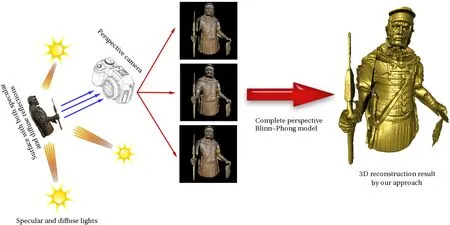
Fig.1 Highly specular photometric stereo setup illustrated by a complex synthetic experiment.In the real world,surfaces show both specular and diffuse reflections,so considering only the diffuse component or only the specular component does not suffice for real world applications.This surface is illuminated by three non-coplanar light sources with both specular and diffuse lighting.Shading due to each light is captured in a perspective CCD camera.By considering all stated assumptions,we are able to recover shape with a high degree of surface details.
The recent work of Mecca et al.[37]also considered perspective PS techniques that may also deal with non-Lambertian effects.In this approach,a model for PS is suggested by considering separately purely specular and purely Lambertian reflections using five input images.Since a purely specular image cannot provide enough information,more images are needed to better recover the 3D shape of an object.As a result,a variational approach in Ref.[38]is considered to solve their model,using ten input images from purely specular or purely diffuse surfaces.Considering only the diffuse component or specular component alone is not sufficient for practical applications.Furthermore,the separate processing of the reflectance models requires input images with a minimum value of saturation[39],which is a cumbersome limitation for some real world applications,e.g.,those with spatially varying materials.Let us note that a similar approach to that of Mecca et al.is also applied in the orthographic PS method in Ref.[39],which is based on dividing the surface into two different,purely specular and purely diffuse parts,a difficult task as they note.
Other works based on separation into specular and diffuse components include Refs.[40–42]. In contrast,by taking into account the complete reflection model,our method does not rely on separation of specular and diffuse reflections at any stage of the computation. Moreover,we do not need any scene division task which is not applicable to general objects.As a side-effect,our method is inherently able to handle objects with spatially varying materials automatically without modification. This is an important step towards reliable PS.
1.3.2Number of input images
We use three input images(readily available in any real world application like endoscopy)in all our experiments.This is the minimum necessary number of inputs for the classic orthographic PS framework with Lambertian reflectance model.Recent work shows that the use of three input images can be advantageous[39].
1.3.3Prior knowledge of depth unnecessary
When solving the resulting hyperbolic PDEs,Mecca et al.[37]relied on the fast marching method.In order to apply this technique,the unknown depth value ofzat a certain surface point(basically the image centre)must be given in advance.The same problem exists for the method in Ref.[38],which needs the mean depth value.However,this information is unknown and is not always available in real world applications.In particular,our scheme does not need any previous depth knowledge about the scene.
1.3.4Smoothness constraints unnecessary
Unlike variational approaches like Ref.[38],we do not use any smoothness constraints for object structure to tackle artifacts which can disrupt the recovery of fine details.Thus,surfaces with delicate geometric structures can be reconstructed by our approach:see Figs.1 and 2.
1.3.5Using specularity information
We explicitly handle specularities instead of treating them as outliers as done in most previous works.Since specularities provide key information for shape estimation,they should be included in PS models.

Fig. 3 Perspective projection of the real point R into the image plane

Fig.2 Comparison of surface reconstruction techniques.Left:input image.Middle:our 3D reconstruction using orthographic projection.Right:our 3D reconstruction using perspective projection.The perspective approach generates a result more compatible with the original image.
1.4 Relation to other work
Our work extends the approach presented by Khanian et al.[43].A main aim of the latter is to study the effect of lighting directions on numerical stability.The presentation is restricted to one spatial dimension and signal reconstruction.Their investigations have motivated us to consider an indicator for good lighting conditions in 3D reconstruction,as presented in Section 2.3.However,since their work is restricted to investigations in 1D,their technical results cannot be directly used in this paper.
2 Perspective projection
In the following,we consider two different approaches to handling perspective projection.The first method computes the normal field and then modifies the gradient field based on the perspective projection,as also proposed in Refs.[44,45].As it manipulates normal vectors,we refer to this technique as theperspective projection based on normal field(PPN)method.The second method considers perspective parameterization of photographed object surfaces to obtain the gradient field of the surface.We call this approach theperspective projection based on surface parameterization(PPS)method.
As we will also consider for experimental comparison a Lambertian perspective PS model,we also recall its construction here. A Lambertian scene with albedokdis illuminated from directionsLk=(αk,βk,γk)T, wherek=1,2,3,by corresponding point light sources at in fi nity,with diffuse intensityld.It thus satisfies the following reflectance equation[1]:

wherekdis the diffuse material parameter,Ik(x,y)andN(x,y)are the intensity and surface normal at pixel(x,y),respectively.
2.1 Modifying normal vectors
The first perspective projection method processes the field of normal vectorsN(x,y)=(n1(x,y),n2(x,y),n3(x,y))T. Once the normal vectors have been reconstructed from the orthographic image irradiance equations, the depth map is recovered by giving the following components in Eq.(2)to the integrator:

where(p,q)constitutes the perspective gradient field for point(x,y)∈¯Ω as the image plane,andd(x,y)for a camera with focal lengthfis

dis the dot product ofOPand normal vectorN(x,y)whereOPis the radial distance of the sensor pointP=(x,y,f)to the optical centerOwhen the camera is located at the origin of the coordinate system.We give the strategy for this projection in Algorihm 1.
2.2 Direct perspective surface parameterization
Another approach to apply the perspective projection is via the corresponding surface parameterization,as shown in Fig.3. In order to project the real world pointRto the pointron the image plane,we consider Thales theorem for both horizontal red and vertical blue triangles.This leads to

However,the image plane¯Ω lies behind the lens.Therefore,the surface is parameterized using the following formulation,wherefis the focal length.For all points inas the image plane:

From this surface parameterization,we can extract the partial derivatives of the surface:

Finally,we get the surface normal vectorNas the cross product of the partial derivatives of the surface:
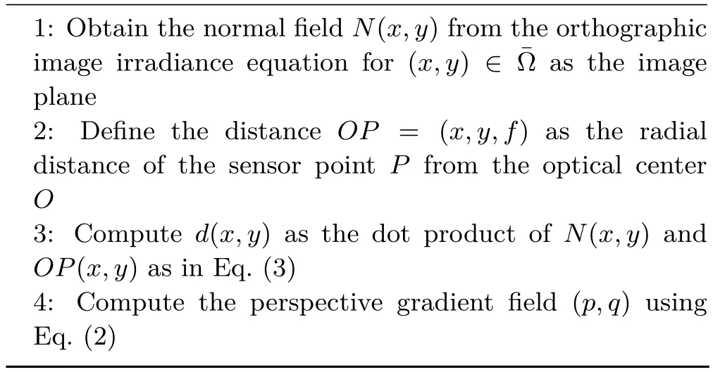
Algorithm 1 Transforming an orthographic normal field to a perspective gradient field

The resulting surface normal is used in the image irradiance equation.
We recall here the Lambertian perspective image irradiance equation[30],as this will be extended in our model.In order to remove the dependency of the image irradiance equation on the unknown depthz,it is replaced byν=ln(z),zx=zνx,zy=zνy,so that we have to applyz=exp(ν)to obtain the depthzfrom our new unknownν.This yields:

A closed form solution for the gradient field is given in Ref.[30].For completeness of the presentation,we recall the main points of its construction.Let us consider three input images(the minimum needed inputs in classic PS).By findingkdfrom the first image irradiance equation in Eq.(9),and replacing it in the second and third image irradiance equations,a linear system of equationsMX=Hmay be solved to obtain the unknown vectorX=(νx,νy):

where,writingri=Ii‖Li‖,

and

The explicit solutions are

We can now obtain the albedo of the surface by substituting the resultant gradient vector into the following equation:

2.3 Sensitivity of the solution
We now assess the sensitivity of the solution to the lighting direction,which may lead to conditions on the illumination.To this end,the non-singularity condition of the matrix of coefficientsMintroduced in the previous paragraph should be explored.The condition detM/= 0,allows us to assure nonsingularity in virtually all cases by ensuring that the contributing terms are not zero.This idea leads to the indicator:

The first three expressions imply the linear independence of lighting directions;it can be also obtained from the non-singularity condition of the light direction matrix.It should be noted that since PPN obtains normal vectors from the orthographic image irradiance equation,the necessary condition for lighting is non-singularity of the lighting directions. The other expressions have different meanings and satisfying all of them may not be an easy task. Consequently,the sensitivity of the solution to the lighting when using the PPS technique can be higher than for the PPN approach.
3 Blinn–Phong reflectance model
We now introduce the Blinn–Phong reflectance model to cope with specular reflections of non-Lambertian materials.To approximate real world surface reflectance,in addition to the Lambertian reflectance,a specular term is introduced in the Blinn–Phong model[34,35]. Most real objects show both kinds of reflections in different areas,and therefore,both reflection models are required at the same time.The Blinn–Phong model uses the angle of incidenceI=arccos(L·N)and also the angleϕ=arccos(H·N)between the vectorNand the vectorH(halfway vector of the light and viewing directions).We consider the Blinn–Phong model under the perspective projection.To this end,we apply again two different mentioned perspective approaches.The basic and complete Blinn–Phong image irradiance equation is whereksis the specular material parameter,lsis the specular light source intensity,and the exponentnis the specular sharpness or shininess.

A corresponding orthographic model has been investigated in the shape-from-shading context in Ref.[46].To develop the perspective Blinn–Phong PS model,we focus on the surface parameterization and substitute the perspective normal in Eq.(8)into Eq.(19).
Usingkinput images with corresponding lighting directions,this yields the perspective Blinn–Phong reflectance equation:

where

3.1 Numerical approach
3.1.1Introduction
We now present the numerical procedure used to solve this highly nonlinear system of equations.We write the system of equations asF(X)=0,whereF:Rn−→Rmis the function in Eq.(20).
In order to cope with such a nonlinear system of equations,we apply the Levenberg–Marquardt method[47,48]which combines the Gauss–Newton method with a steepest descent direction technique.In this method,ifXkis the point at iterationk,the next iteration can be computed as

withλk>0.
The matrixJF(Xk)JF(Xk)T+λkIis positive definite anddkis well-defined.This method does not need such conditions as the invertibility of the Jacobian or Hessian matrices orm=n.
3.1.2Partial linearization strategy
Our numerical approach for the PPS method is based on the following formulation which makes the problem much easier to handle by providing a partially linearized system from the highly nonlinear system of equations.Recalling the perspective Blinn–Phong reflectance equation in Eq.(20),and dividing three equations(I1/I2,I2/I3,I1/I3),corresponding to the three images used in our method leads to a system of equations.For example,using the first and second images,we proceed as follows.
Integrating the two terms in Eq.(20)results in:

Dividing the irradiance equations for the first and second images leads to
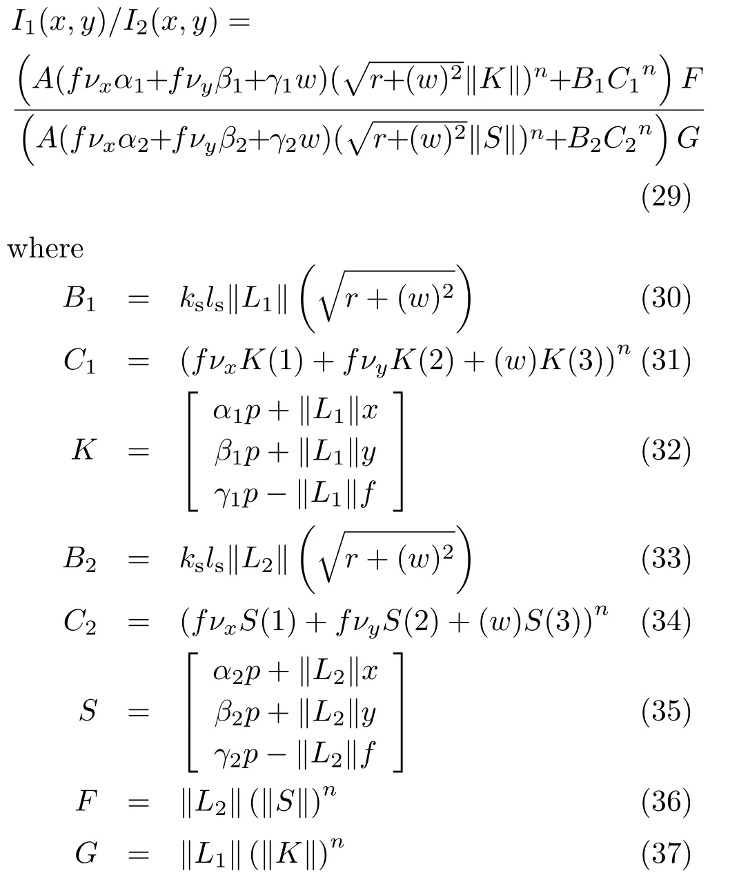
Unifying the two fractions in Eq.(29)gives:


Using the same approach forI2/I3andI1/I3gives the partially linearized system of equations.It should be noted that even in this case where specularities exist,and we solve the perspective PS system for the Blinn–Phong model in Eq.(20),we will still follow Woodham and make use of only three input images.
Furthermore,as for the case of Lambertian PS,we deal with the Blinn–Phong model using the perspective version based on transforming the normal vectors(thePPN method),i.e.,after using orthographic Blinn–Phong PS.Finally,the obtained gradient fields are processed by the Poisson integrator.See,e.g.,Ref.[49]for a recent account of surface normal integration.
4 CCD cameras
We now investigate modeling of the CCD camera.The following projection mapping is used,as given in Ref.[36].The matrix

contains the intrinsic parameters of the camera,namely the focal lengths inx-andy-directions equal toψx=f/hxandψy=f/hy,with sensor sizeshxandhyand principal or focal point(δx,δy)T. The parameterξis called the skew.Here,we neglect this parameter since it is zero for most normal cameras[36].Using this matrix,we introduce the following transformation to convert the dimensionless pixel coordinatesX=(x,y,1)Tto image coordinatesχ=(c,d,f)T:

Applying this transformation gives the following representation for the projected pointχ:

The effect of this modeling is potentially interesting,since this information is not always accessible.The above transformation is calledcenteringin experiments.
5 Experiments
5.1 Setting
This section describes our experiments on our proposed model and approaches.In a first test we con fi rm the findings of Tankus et al.[18]that the use of an orthographic camera model may yield visible distortion in the reconstruction while a perspective model may take the geometry better into account:see the experiment documented in Fig.2;note that the object of interest is relatively close to the camera.This justi fi es the use of a perspective camera model.
In a series of tests we now turn to quantitative evaluations of the proposed computational models using the sets of test images shown in Fig.4.The Beethoven test images(which depict a real world scene)and the sphere images are of size 128×128.The Stanford Bunny test images have a resolution of 150×120.Both Bunny and sphere were rendered using Blender.The 3D model of the Stanford Bunny was obtained from the Stanford 3D scanning repository[50].The 3D model of the face presented in Fig.12 is taken from Ref.[51]with the size of 256×256.For evaluation,the ground truth depth maps are extracted,and we use mean squared error(MSE)to assess accuracy.
After the evaluation, we demonstrate the applicability of our method to real world medical test images from gastroendoscopy,and then discuss its superior reconstruction capabilities compared to previous models.
5.2 Tests of accuracy
In the first evaluation,we compare results of the PPN and PPS perspective techniques applied to the specular sphere in Fig.4(c),with different values of focal length.MSE results of these 3D reconstructions are shown in Fig.5. While the results for low focal lengths are close to each other,the PPN perspective strategy outperforms PPS as the focal length increases.
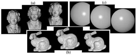
Fig. 4 Set of three test images used for our 3D reconstruction:(a)real scene used for reprojecting;(b,c)rendered images used for 3D reconstruction in presence of specularity.

Fig.6 Reprojected Beethoven images.Left:second input image for PS.Middle:reprojected second image obtained using the PPN method.Right:reprojected second image using the PPS method.
In the second experiment using the Beethoven image set,we investigate the difference between the perspective approaches on a more complex real world object scene.Table 1 gives an MSE comparison of gray levels for the reprojected and input images.Since in this case the ground truth depth map is not available,we reconstruct the reprojected images by obtaining the gradient fields using the two perspective approaches and replace them in the Lambertian reflectance equation.Table 1 shows that reprojecting from the PPS results closely matches the third input image,while the PPN approach better matches the first and second input images,especially the latter.As the reprojected images in Fig.6 show,the difference between these methods as given in Table 1 can be quite significant.Furthermore,it is indicative of higher sensitivity of the PPS method to the lightening than the PPN approach.

Table 1 MSE comparison for the reprojected Beethoven images using PPN and PPS perspective methods
5.3 Slant and tilt
Two well-known indicators of 3D information are slant and tilt[52].Individual neurons in our brain’s caudal intraparietal area(a critical neural locus for encoding 3D information of objects)are responsible for encoding slant and tilt of surfaces[53,54].Here,we performed some experiments to probe the behaviour of both proposed perspective techniques for slant and tilt parameters,as a proxy for the perceptual properties of the surface[55,56].Slant is defined as the angle between the surface normal and the line of sight,while the tilt angle determines the orientation of the surface normal projection on the fronto-parallel plane(the plane perpendicular to the viewing direction,also called image plane),as shown in Fig.7.In perspective projection,we deal with the surface gradient field(p,q),from which slant and tilt can be computed as follows[56]:

In PPN,the gradient field is computed from Eq.(2),while in PPS it is obtained using:

Variations of slant and tilt on a unit sphere are shown in Fig.8.As can be seen,the slant parameter changes in the interval of[0°,90°],whereas tilt varies in[0°,180°].
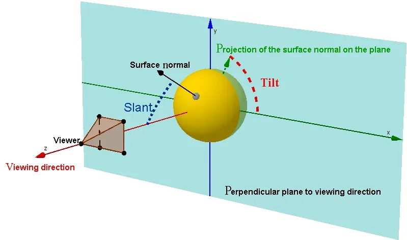
Fig.7 Slant and tilt angular variables are important parameters for encoding 3D perceptions in our brain[53,54].The tilt of a surface corresponds to the direction of largest variation in perceived distance while slant varies with the magnitude of the gradient according to Eq.(42).
To conduct a fair comparison between PPN and PPS influence on 3D information,we obtained tilt and slant angles for a unit sphere using those two projections,and calculated the mean square error in obtained angles(MSEA).It is important to note that any deviation in tilt reconstruction leads to false perception of theobject orientationwhich is not detrimental for the perception of a symmetric 3D shape such as a sphere,whilst erroneous slant estimation results in the loss of the object curvature understanding. In other words,the geometrical interpretation of an erroneous slant estimation is the distorted curvature of the reconstructed surface.As can be seen in Figs.9 and 10,the estimation error of both tilt and slant angles diminishes with increasing focal length. Figure 9 reveals that estimated tilt values for both perspective projection methodsremain close,and donotprovidea preference for either method.In contrast,curvature estimation accuracy given in Fig.10 shows more successful performance of the PPN approach to preserve curvature properties of the surface during 3D reconstruction process.
Ourconclusion is in accordance with some previous studies on the human visual system[57,58],where it turns out that perspective characteristics of the human visual system are the main source of slant perception.
5.4 Perspective methods and CCD camera model
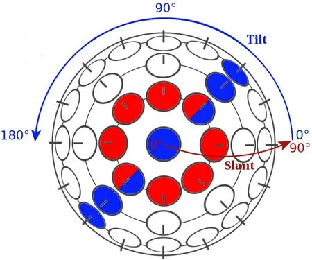
Fig.8 Slant(red)and tilt(blue)components of surface orientation on a unit sphere.Red circles(including two bi-colors)represent an area with equal slant angels and blue circles(including two bi-colors)indicate an area with equal tilt angels on the sphere.

Fig.9 Mean square error of tilt(MSEA in degrees)for two perspective techniques applied on the sphere for different focal lengths.The error in estimated tilt angle decreases with increasing focal length.

Fig. 10 Mean square error of slant(MSEA in degrees)for two perspective techniques applied on the sphere for different focal lengths.The error is decreasing with gradually increasing focal length.PPN perspective projection yields more decrease than the PPS perspective technique.
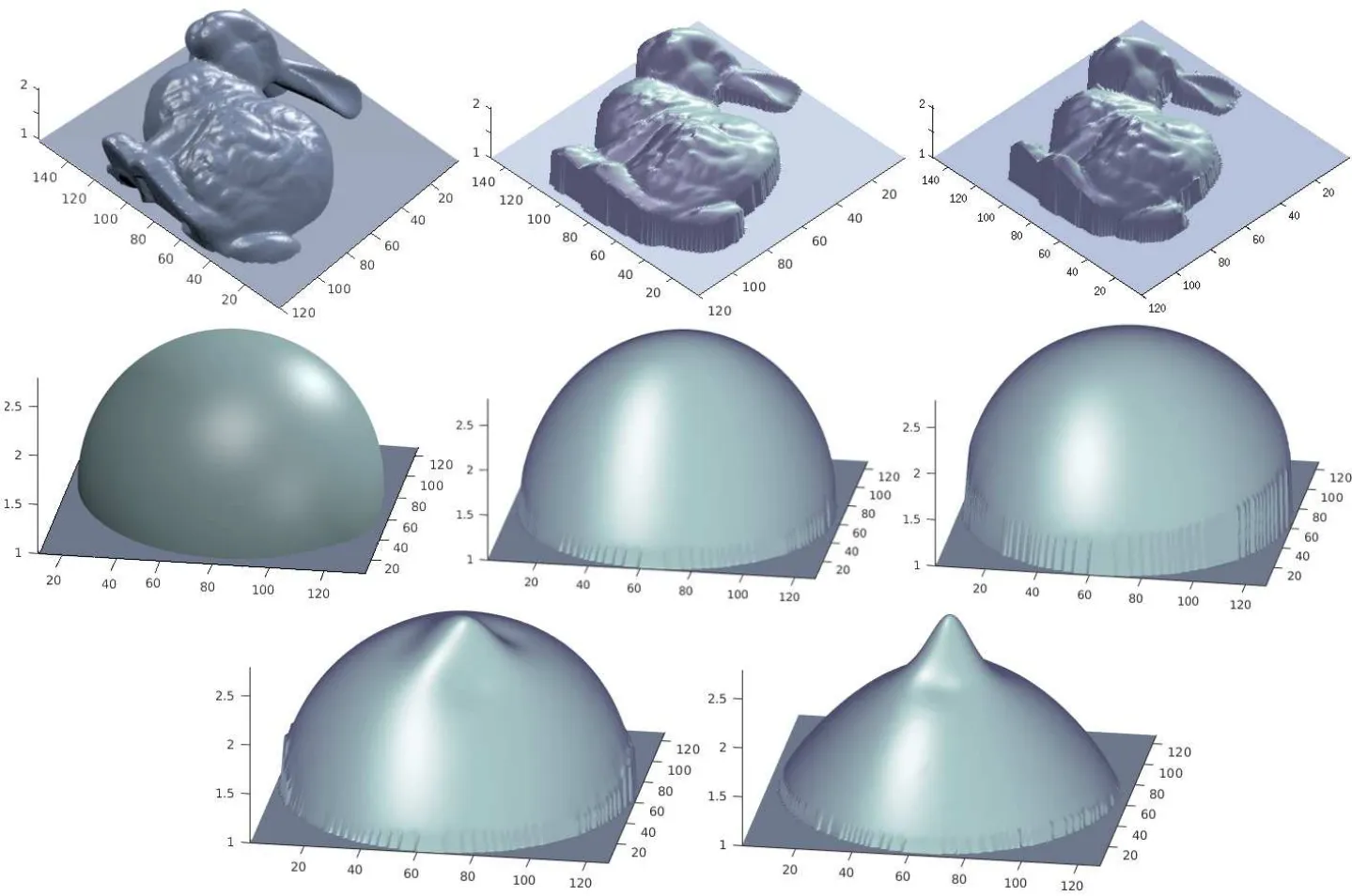
Fig.11 Fisrt and second rows:left:ground truth;middle:depth reconstruction using complete Blinn–Phong model with PPN approach;right:depth reconstruction using Blinn–Phong model with PPS approach.The methods produce appealing reconstruction of images with strong specularities.The PPN approach provides more faithful reconstructions.Last row:depth reconstruction using a Lambertian model in the presence of specularity,with different perspective projection methods.Left:PPN approach;right:PPS approach.The Lambertian model is unable to provide a faithful reconstruction for specular surfaces.

Table 2 MSE in depth reconstructed from images with specularities,using PPN and PPS methods.We consider 3D reconstruction in the presence of simultaneous diffuse and specular reflections from the surface which leads to involving both kdand ksusing a complete Blinn–Phong model
Table 2 and Fig.11 present 3D reconstruction results for some highly specular input images shown in Figs.4(b)and 4(c). In order to produce such images,we set non-zero intensities for diffuse and also specular lighting. Furthermore,the objects include both diffuse and specular reflections.Values of MSE for 3D reconstruction show the high accuracy of our depth reconstructions produced by applying the complete Blinn–Phong model in conjunction with the two perspective schemes presented.
On the other hand,while results of the recovered depth map for the sphere are close to some extent,the outcome of the outcome of the computed depth map for Bunny based on the PPN method obtains higher accuracy. However,the table also illustrates the higher sensitivity of the PPN perspective scheme to centering transformation than the PPS perspective method.
Finally,we compare our approach with the model,the most common model applied in PS and also the method presented by Mecca et al.[37].The last row in Fig.11 shows the outcome of applying the Lambertian model.The deviation from faithful reconstruction over the specular area of the surface can be seen clearly.The comparison between our approach and Ref.[37]is also shown in Fig.12.Our method applies a complete perspective Blinn–Phong model on the three images including both diffuse and specular reflections and lights,while the method in Ref.[37]uses the specular term in the Blinn–Phong model to handle four purely specular images.The excellent results of our method presented in Fig.12(b)in the presence of a high value of specularity,lacking artefacts,show that the proposed method outperforms state-of-the-art approaches such as the one in Ref.[37].MSE values of 3D reconstruction associated with the experiments in Fig.12 are also given in Table 3.
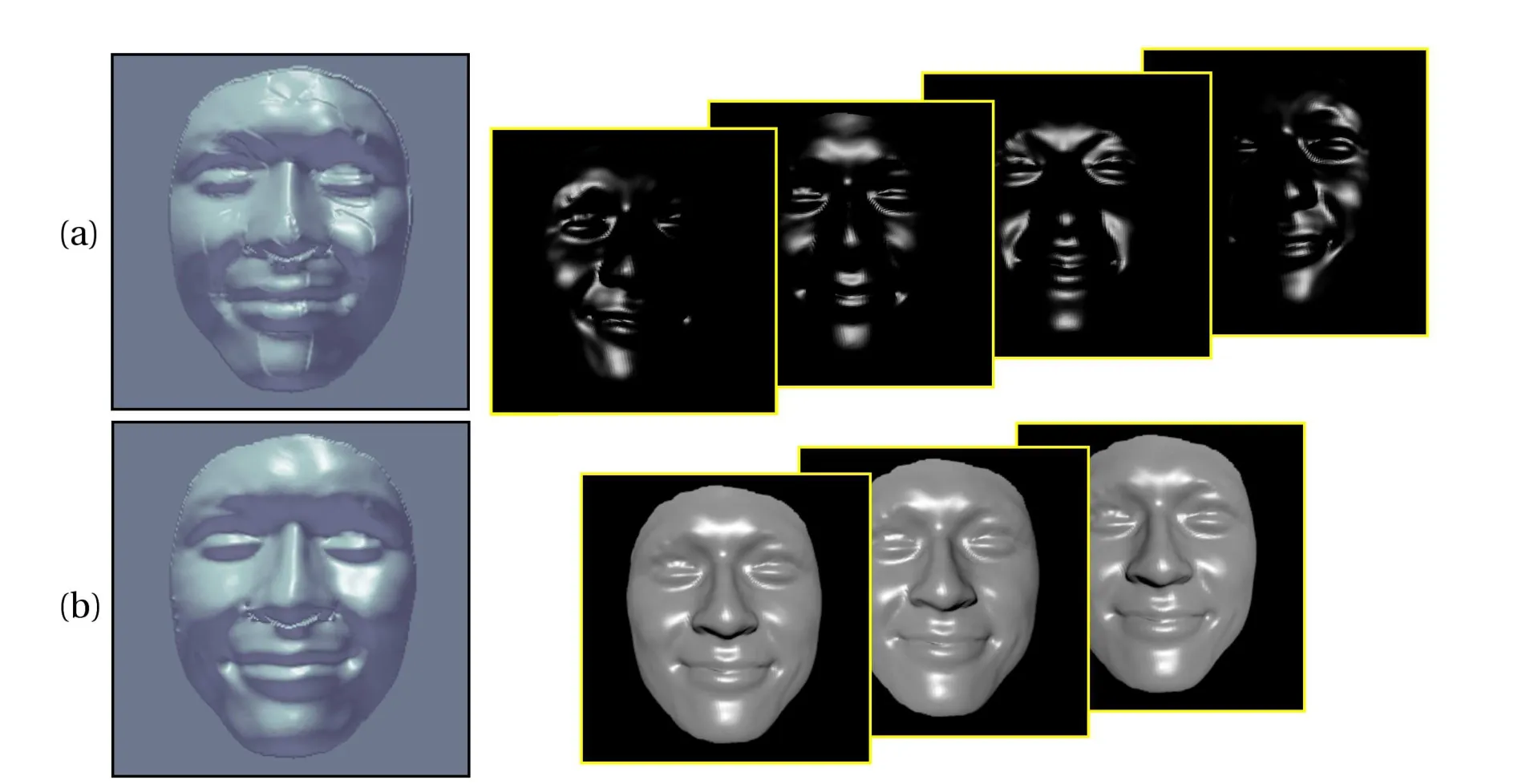
Fig.12 First row:four purely specular input images as applied the purely specular model of Ref.[37]and the 3D reconstruction by that approach,which shows artefacts especially around the highly specular areas.Second row:three ordinary input images including both diffuse and specular components used as input to our method and our 3D reconstruction.Our method does not need to decompose the input images into purely diffuse and purely specular components,a very difficult task even for synthetic images.

Table 3 MSE of the reconstructed depth from images with high specularities shown in Fig.12
5.5 Applicability to real world test images
This section describes experiments conducted by the proposed approach on realistic images.
We first turn to some real world medical test images.They are realistic in that we did not benefit from a controlled setup or additional laboratory facilities.We used images that are available as in any kind of medical(or many other real world)experiments.Endoscopic images are well known to providea challenging test and are widely accepted for indicating possible medical applications of photometric approaches(see,e.g.,Refs.[59,60]).The usefulness of the computational results of our work to concrete medical applications has been con firmed by collaboration with specialized medical doctors①E.g.,with Dr.Mohammad Karami H.(Dr.mokaho@skums.ac.ir)who is a gastroenterologist and internal medicine specialist at Shahrekord University of Medical Science,Iran,whom we thank for providing the endoscopy images..
We have performed trials on endoscopic images in which existence of high specularities is unavoidable.Input images are presented in Figs.13(a)and 13(b)which are endoscopies of the upper gastrointestinal system.Their 3D reconstructions are represented in Figs.14 and 15.
As in the previous experiments,only three input images are used.All outputs are displayed with an identical viewpoint enabling their visual comparison.The first column in Fig.14 illustrates the deviations in the Lambertian result.In the cropped region in Fig.13(a),shown in the rectangle,the beginning and end points of all three folds(marked A,B,and C)should be at about the same level,but instead a drastic deviation downwards occurs at the left side of the surface(see Fig.14(a))in results obtained using the Lambertian reflectance model,as also indicated by the blue area in the corresponding depth map shown in Fig.14(d).
However,this deviation is rectified by applying the complete Blinn–Phong model accompanied by PPS,as can be seen in the second column of Fig.14 and also entirely corrected using this model with PPN approach as represented in the third column in Fig.14.Furthermore,three folds of the surface are reconstructed very well in the Blinn–Phong outcomes(second and third columns of Fig. 14). This obviously desirable complete reconstruction of folds is lacking in the Lambertian output.

Fig.13 Test images with high specularity from a realistic real world scenario.These images were produced by endoscopy,without benefiting from any laboratory facilities or controlled setup conditions.
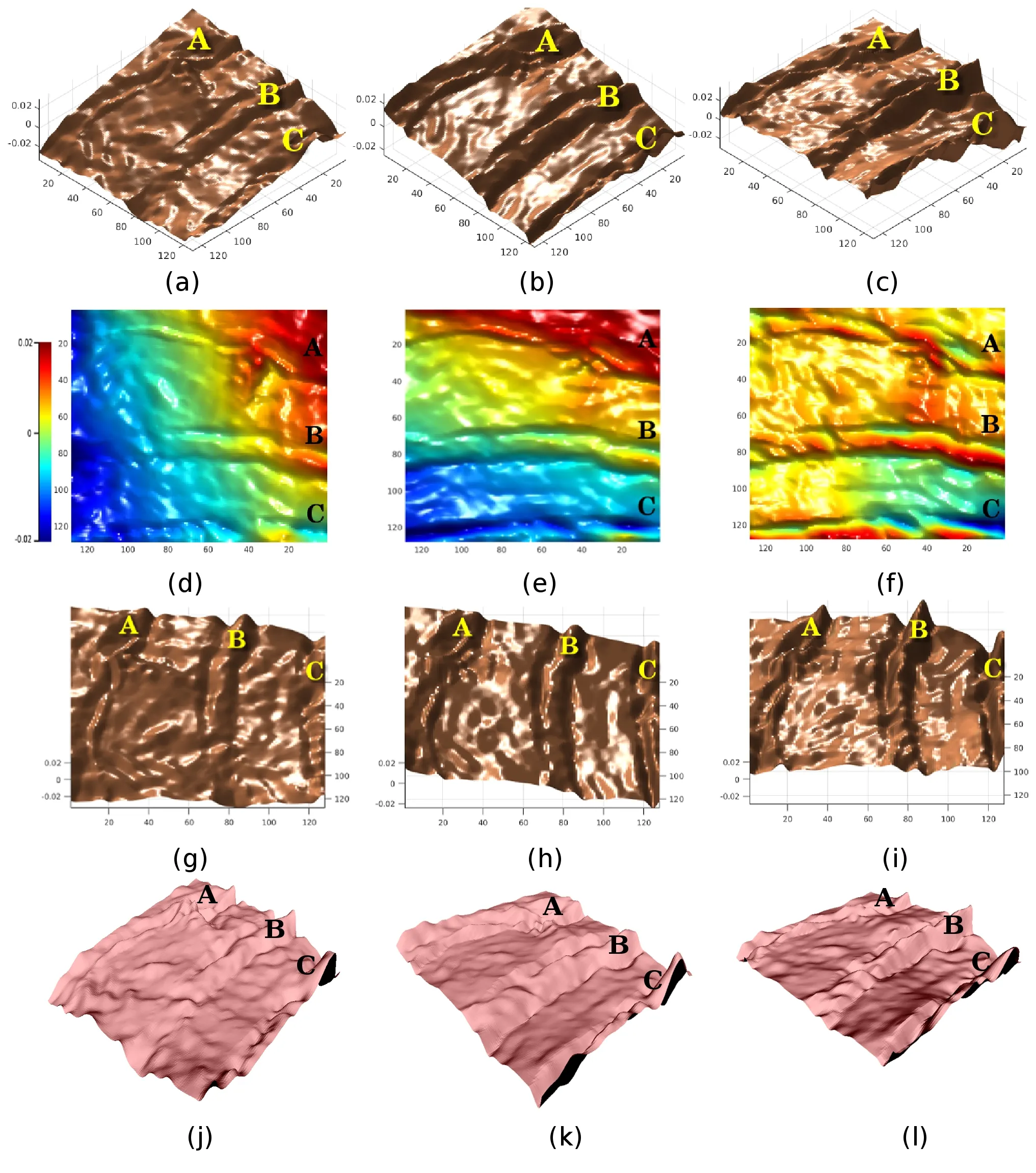
Fig.14 Depth reconstruction results from real world endoscopy images.First column:using a Lambertian model.Second column:using a Blinn–Phong model with PPS.Third column:using a Blinn–Phong model with PPN.All images are shown using an identical view to visualize differences.Deviations in the Lambertian results can be clearly seen,while the results of our approach provide faithful 3D reconstructions without deviations and also with a high amount of details.
Finally,as also the color variation in the depth maps in the second row of Fig.14 shows,high frequency details are recovered as well in the Blinn–Phong outputs,especially for the PPN approach.
These reconstruction aspects are again clearly observable in another endoscopy image depth reconstruction in Fig.15 which are the depth resultings from the inputs in Fig.13(b).Once more,a deviation from the desirable output shape appears in the Lambertian outcome,especially on the left corner side(Fig.15(a)).This part of the surface,marked C in the input and 3D results,has a cavity towards the upper side in reality,which is reconstructed well by the Blinn–Phong outputs in contrast to the Lambertian result.The Lambertian model instead provides a reconstruction on the opposite side for this region of the original surface.Let us pay attention also to the second row of Fig.15 displying depth maps.A curved line of the upper corrugated region A is obtained in the right corner of the Blinn–Phong outputs(Figs.15(e)and 15(f)),whereas this region is just a straight line in the Lambertian outcome(Fig.15(d)).The heights of corrugated regions are obviously more faithfully reconstructed in the Blinn–Phong results than the Lambertian one.

Fig.15 Depth reconstruction results from real world endoscopy images.First column:using a Lambertian model.Second column:using a Blinn–Phong model with PPS.Third column:using a Blinn–Phong model with PPN.All images are shown using an identical view to visualize differences.Once more,the deviations in Lambertian outcomes is clear,whereas our approach provides a trustable 3D reconstruction without deviation.
Last but not least,it is worth mentioning that the viewing angle of endoscopy cameras is very tight. Using cropped parts of those images in our experiments provides a highly challenging 3D reconstruction task.The success of our approach in reconstructing such a tiny range of depth values without any knowledge of photographic conditions reveals the capability of our proposed method in challenging real world applications.
In another test with real world input images,we compared our method with the approach used in Ref.[30]by making use of the input images given in Figs.2(a)–2(c)of Ref.[30].The surface is a plastic mannequin head,which shows specularities.It is well-known in computer graphics that plastic is a material that can be readily rendered using the Blinn–Phong model[61].
The depth reconstructions obtained by our technique and the method of Tankus for those real world images are presented in Figs.16 and 17.Once again,the deviation from a natural shape in the Lambertian result of Ref.[30]can be clearly observed in the output in Fig.16(b),shown from an identical view with our result in Fig.16(a).In addition,let us note that the output of the Blinn–Phong model is very clear and smooth,even for highlights.The inhomogeneous recovery of the shape when using the Lambertian model is cropped in some regions such as chin and tip of the nose(see Fig.16(c)),where we had to turn the Lambertian result to show these regions.The curved lines appearing in the chin and the sharp point at the nose in the Lambertian reconstruction are also visible in Ref.[30].Moreover,as noted in Ref.[30],they could not process eyes in images,due to specularities,while we succeeded in recovering a faithful 3D shape with the eyes using the complete Blinn–Phong model(see Fig.17).

Fig.16 Depth reconstructions from real world images.(a)Results of our proposed method using the Blinn–Phong model.(b,c)Results using the method of Ref.[30].Both images are shown from identical viewpoints to visualize the differences.Cropped parts of results from both methods are shown in(c).Our approach shows significant superiority in terms of advantages such as smoothness,reconstruction success in specularities,and absence of deviation from the natural symmetric shape.
6 Summary and conclusions
A new framework for PS has been presented using a complete perspective Blinn–Phong reflectance model which can deal with strong specular highlights.The advantages of our method over state-of-the-art PS methods and also the Lambertian model are proved via a variety of experiments.The model includes a perspective camera projection.Furthermore,two different techniques to implement the perspective projection have been evaluated.In addition,we have also considered the modeling of a CCD camera.All results are obtained using a minimum necessary number of input images,an aspect of practical relevance in real applications.This makes PS an interesting technique for being close to real-time reconstruction,where a minimal set of images should be used.We have also demonstrated experimentally the merits of our PS model for challenging real world applications,where we recover the surface with a high degree of detail.Let us also comment that our computational time is very reasonable,i.e.,of the order of a few seconds in all experiments.
Concerning possible limitations, as with allthe possible approaches that rely on a parametric representation of surface reflectance,the corresponding additional parameters in the reflectance function have to be fixed.This issue may provide challenging numerical issues in optimization.Also,while we have demonstrated that the Blinn–Phong model already gives reasonable results,other more sophisticated reflectance models may be useful for handling highly complicated surfaces,providing a possible topic for future research.

Fig.17 Depth reconstructions from real world images.(a)Results of our proposed method using the Blinn–Phong model.(b)Results using the method of Ref.[30].As noted in Ref.[30],they could not obtain the 3D reconstruction in the presence of eyes(due to the specularities)unlike our approach which provides faithful results even with including eyes.
Acknowledgements
This work was supported by the Deutsche Forschungsgemeinschaft under grant number BR2245/4–1. The authors would like to thank the anonymous reviewers for helpful comments to improve the quality of the paper.
References
[1]Horn,B.K.P.Robot Vision.The MIT Press,1986.
[2]Trucco,E.;Verri,A.Introductory Techniques for 3-D Computer Vision.Prentice Hall PTR,1998.
[3]Whler,C.3D Computer Vision.Springer-Verlag,2013.
[4]Ihrke,I.;Kutulakos,K.N.;Lensch,H.P.A.;Magnor,M.;Heidrich,W.Transparent and specular object reconstruction.Computer Graphics ForumVol.29,No.8,2400–2426,2010.
[5]Xiong,Y.;Shafer,S.A.Depth from focusing and defocusing.In:Proceedings of the IEEE Conference on Computer Vision and Pattern Recognition,68–73,1993.
[6]Faugeras,O.Three-Dimensional Computer Vision.The MIT Press,1993.
[7]Tomasi,C.;Kanade,T.Shape and motion from image streams under orthography:A factorization method.International Journal of Computer VisionVol.9,No.2,137–154,1992.
[8]Adato,Y.;Vasilyev,Y.;Zickler,T.;Ben-Shahar,O.Shape from specular fl ow.IEEE Transactions on Pattern Analysis and Machine IntelligenceVol.32,No.11,2054–2070,2010.
[9]Godard,C.;Hedman,P.;Li,W.;Brostow,G.J.Multi-view reconstruction of highly specular surfaces in uncontrolled environments.In:Proceedings of the International Conference on 3D Vision,19–27,2015.
[10]Sankaranarayanan,A.C.;Veeraraghavan,A.;Tuzel,O.;Agrawal,A.Specular surface reconstruction from sparse reflection correspondences.In:Proceedings of the IEEE Computer Society Conference on Computer Vision and Pattern Recognition,1245–1252,2010.
[11]Woodham,R.J.Photometric stereo:A reflectance map technique for determining surface orientation from image intensity.In:Proceedings of the SPIE 0155,Image Understanding Systems and Industrial Applications I,136–143,1978.
[12]Horn,B.K.P.;Woodham,R.J.;Silver,W.M.Determining shape and reflectance using multiple images.MIT Arti fi cial Intelligence Laboratory,Memo 490,1978.
[13]Woodham,R.J.Photometric method for determining surface orientation from multiple images.Optical EngineeringVol.19,No.1,134–144,1980.
[14]Lambert,J.H.;DiLaura,D.L.Photometry,or,on the measure and gradations of light,colors,and shade:Translation from the Latin of photometria,sive,de mensura et gradibus luminis,colorum et umbrae.Illuminating Engineering Society of North America,2001.
[15]Beckmann, P.; Spizzichino, A.TheScattering of Electromagnetic Waves fromRoughSurfaces.Norwood,MA,USA:Artech House,Inc.,1987.
[16]Brandenberg,W.M.;Neu,J.T.Undirectional reflectance of imperfectly diffuse surfaces.Journal of the Optical Society of AmericaVol.56,No.1,97–103,1966.
[17]Tagare,H.D.;De fi gueiredo,R.J.P.A framework for the construction of general reflectance maps for machine vision.CVGIP:Image UnderstandingVol.57,No.3,265–282,1993.
[18]Tankus,A.;Sochen,N.;Yeshurun,Y.Shape-fromshading under perspective projection.International Journal of Computer VisionVol.63,No.1,21–43,2005.
[19]Mukaigawa,Y.;Ishii,Y.;Shakunaga,T.Analysis of photometric factors based on photometric linearization.Journalof theOpticalSocietyof America AVol.24,No.10,3326–3334,2007.
[20]Mallick,S.P.;Zickler,T.E.;Kriegman,D.J.;Belhumeur,P.N.Beyond Lambert:Reconstructing specular surfaces using color.In:Proceedings of the IEEE Computer Society Conference on Computer Vision and Pattern Recognition,Vol.2,619–626,2005.
[21]Yu,C.;Seo,Y.;Lee,S.W.Photometric stereo from maximum feasible Lambertian reflections.In:Computer Vision–ECCV 2010.Lecture Notes in Computer Science,Vol,6314.Daniilidis,K.;Maragos,P.;Paragios,N.Eds.Springer,Berlin,Heidelberg,115–126,2010.
[22]Miyazaki,D.; Hara,K.; Ikeuchi,K.Median photometric stereo as applied to the segonko tumulus and museum objects.International Journal of Computer VisionVol.86,Nos.2–3,229–242,2010.
[23]Tang,K.-L.;Tang,C.-K.;Wong,T.-T.Dense photometric stereo using tensorial belife propagation.In: Proceedings of the IEEE Computer Society Conference on Computer Vision and Pattern Recognition,Vol.1,132–139,2005.
[24]Wu,L.;Ganesh,A.;Shi,B.;Matsushita,Y.;Wang,Y.;Ma,Y.Robust photometris stereo via low-rank matrix completion and recovery.In:Computer Vision–ACCV 2010.Lecture Notes in Computer Science,Vol.6494.Kimmel,R.;Klette,R.;Sugimoto,A.Eds.Springer,Berlin,Heidelberg,703–717,2010.
[25]Smith,W.;Fang,F.Height from photometric ratio with model-based light source selection.Computer Vision and Image UnderstandingVol.145,128–138,2016.
[26]Hertzmann,A.;Seitz,S.M.Shape and materials by example: A photometric stereo approach.In:Proceedings of the IEEE Computer Society Conference on Computer Vision and Pattern Recognition,Vol.1,I-533–I-540,2003.
[27]Goldman,D.B.;Curless,B.;Hertzmann,A.;Seitz,S.M.Shapeandspatially-varyingBRDFsfrom photometric stereo.IEEE Transactions on Pattern Analysis and Machine IntelligenceVol.32,No.6,1060–1071,2010.
[28]Oxholm,G.;Nishino,K.Multiview shapeand reflectance from natural illumination.In:Proceedings of the IEEE Conference on Computer Vision and Pattern Recognition,2163–2170,2014.
[29]Galo,M.;Tozzi,C.L.Surface reconstruction using multiple light sources and perspective projection.In:Proceedings of the 3rd IEEE International Conference on Image Processing,Vol.2,309–312,1996.
[30]Tankus,A.;Kiryati,N.Photometric stereo under perspective projection.In:Proceedings of the 10th IEEE International Conference on Computer Vision,Vol.1,611–616,2005.
[31]Mecca,R.;Tankus,A;Bruckstein,A.M.Twoimage perspective photometric stereo using shapefrom-shading.In:Computer Vision–ACCV 2012.Lecture Notes in Computer Science,Vol.7727.Lee,K.M.;Matsushita,Y.;Rehg,J.M.;Hu,Z.Eds.Springer,Berlin,Heidelberg,110–121,2013.
[32]Vogel,O.;Valgaerts,L.;Breuß,M.;Weickert,J.Making shape from shading work for real-world images.In:Pattern Recognition.Lecture Notes in Computer Science,Vol.5748.Denzler,J.;Notni,G.;Sße,H.Eds.Springer,Berlin,Heidelberg,191–200,2009.
[33]Cho,S.-Y.;Chow,T.W.S.Shape recovery from shading by a new neural-based reflectance model.IEEE Transactions on Neural NetworksVol.10,No.6,1536–1541,1999.
[34]Blinn,J.F.Models of light reflection for computer synthesized pictures.In: Proceedings of the 4th Annual Con ferenceon Computer Graphics and Interactive Techniques,192–198,1977.
[35]Phong,B.T.Illumination for computer generated pictures.Communications of ACMVol.18,No.6,311–317,1975.
[36]Hartley,R.;Zisserman,A.Multiple View Geometry in Computer Vision.Cambridge University Press,2003.
[37]Mecca,R.; Rodol`a,E.; Cremers,D.Realistic photometric stereo using partial differential irradiance equation ratios.Computers&GraphicsVol.51,8–16,2015.
[38]Mecca,R.;Quau,Y.Unifying diffuse and specular reflections for the photometric stereo problem.In:photometric stereo problem. In:Proceedings of the IEEE Winter Conference on Applications of Computer Vision,1–9,2016.
[39]Tozza,S.;Mecca,R.;Duocastella,M.;Del Bue,A.Direct differential photometric stereo shape recovery of diffuse and specular surfaces.Journal of Mathematical Imaging and VisionVol.56,No.1,57–76,2016.
[40]Kim,H.;Jin,H.;Hadap,S.;Kweon,K.Specular reflection separation using dark channel prior.In:Proceedings of the IEEE Conference on Computer Vision and Pattern Recognition,1460–1467,2013.
[41]Mallick,S.P.;Zickler,T.E.;Kriegman,D.J.;Belhumeur,P.N.Beyond Lambert:Reconstructing specular surfaces using color.In:Proceedings of the IEEE Computer Society Conference on Computer Vision and Pattern Recognition,Vol.2,619–626,2005.
[42]Tan, R.T.; Ikeuchi, K.Separating reflection components of textured surfaces using a single image.IEEE Transactions on Pattern Analysis and Machine IntelligenceVol.27,No.2,178–193,2005.
[43]Khanian,M.;Shari fiBoroujerdi,A.;Breuß,M.Perspective photometric stereo beyond Lambert.In:Proceedings of Vol.9534,the 12th International Conference on Quality Control by Arti fi cial Vision,95341F,2015.
[44]Papadhimitri,T.;Favaro,P.A new perspective on uncalibrated photometric stereo.In:Proceedings of the IEEE Conference on Computer Vision and Pattern Recognition,1474–1481,2013.
[45]Quau,Y.;Durou,J.-D.Edge-preserving integration of a normal field:Weighted least-squares,TV andL1approaches.In:Scale Space and Variational Methods in Computer Vision.Lecture Notes in Computer Science,Vol.9087.Aujol,J.F.;Nikolova,M.;Papadakis,N.Eds.Springer,Cham,576–588,2015.
[46]Camilli,F.;Tozza,S.A unified approach to the wellposedness of some non-Lambertian models in shapefrom-shading.SIAM Journal on Imaging SciencesVol.10,No.1,26–46,2017.
[47]Levenberg,K.A method for the solution of certain non-linear problems in least squares.Quarterly of Applied MathematicsVol.2,No.2,164–168,1944.
[48]Marquardt,D.An algorithm forleastsquares estimation on nonlinear parameters.Journal of the Society of Industrial and Applied MathematicsVol.11,No.2,431–441,1963.
[49]Bhr,M.; Breuß,M.; Quau,Y.; Boroujerdi,A.S.;Durou,J.-D.Fast and accurate surface normal integration on non-rectangular domains.Computational Visual MediaVol.3,No.2,107–129,2017.
[50]The Stanford 3D scanning repository.Available at http://graphics.stanford.edu/data/3Dscanrep/.
[51]Sumner,R.W.;Popovi´c,J.Deformation transfer for triangle meshes.ACM Transactions on GraphicsVol.23,No.3,399–405,2004.
[52]Norman,J.F.;Todd,J.T.;Norman,H.F.;Clayton,A.M.;McBride,T.R.Visual discrimination of local surface structure:Slant,tilt,and curvedness.Vision ResearchVol.46,Nos.6–7,1057–1069,2006.
[53]Rosenberg,A.;Cowan,N.J.;Angelaki,D.E.The visual representation of 3D object orientation in parietal cortex.Journal of NeuroscienceVol.33,No.49,19352–19361,2013.
[54]Sugihara,H.;Murakami,I.;Shenoy,K.V.;Andersen,R.A.;Komatsu,H.Response of MSTD neurons to simulated 3D orientation of rotating planes.Journal of NeurophysiologyVol.87,No.1,273–285,2002.
[55]Saunders,J.A.;Knill,D.C.Perception of 3D surface orientation from skew symmetry.Vision ResearchVol.41,No.24,3163–3183,2001.
[56]Stevens,K.A.Surface tilt(the direction of slant):A neglected psychophysical variable.Perception&PsychophysicsVol.33,No.3,241–250,1983.
[57]Braunstein,M.L.;Payne,J.W.Perspective and form ratio as determinants of relative slant judgments.Journal of Experimental PsychologyVol.81,No.3,584–590,1969.
[58]Tibau,S.; Willems,B.; Van Den Bergh,E.;Wagemans,J.The role of the centre of projection in the estimation of slant from texture of planar surfaces.PerceptionVol.30,No.2,185–193,2001.
[59]Tankus,A.;Sochen,N.;Yeshurun,Y.Reconstruction of medical images by perspective shape-from-shading.In:Proceedings of the 17th International Conference on Pattern Recognition,Vol.3,778–781,2004.
[60]Tatemasu,K.;Iwahori,Y.;Nakamura,T.;Fukui,S.;Woodham,R.J.;Kasugai,K.Shape from endoscope image based on photometric and geometric constraints.Procedia Computer ScienceVol.22,1285–1293,2013.
[61]Pharr,M.;Jakob,W.;Humphreys,G.Physically Based Rendering:From Theory to Implementation.Morgan Kaufmann Publishers Inc.,2010.
杂志排行
Computational Visual Media的其它文章
- Surface tracking assessment and interaction in texture space
- A 3D morphometric perspective for facial gender analysis and classification using geodesic path curvature features
- Robust edge-preserving surface mesh polycube deformation
- Transferring pose and augmenting background for deep human image parsing and its applications
- Adaptive slices for acquisition of anisotropic BRDF
- Image editing by object-aware optimal boundary searching and mixed-domain composition
