Surface tracking assessment and interaction in texture space
2018-05-11JohannesFurchAnnaHilsmannandPeterEisert
Johannes FurchAnna Hilsmannand Peter Eisert()
The Author(s)2017.This article is published with open access at Springerlink.com
1 Introduction
Elaborate video manipulation in post-production often requires means to move image overlays or corrections along with the apparent motion of an image sequence,a task termedmatch movingin the visual effects community.The most common commercial tracking tools available to extract the apparent motion include manual keyframe warpers,point trackers,dense vector generators(for optical fl ow),planar trackers,keypoint match-based camera solvers(for rigid motion),and 3D model-based trackers[1–3]. Many of these tools allow for some kind of user interaction to guide,assist,or improve automatically generated results.However,while increasingly being discussed in the research community[4–6],visual effects artists have not yet adopted user interaction with dense optical flow based estimation methods. We believe this is due to the technical aims of most proposed tools,their relative complexity of usage,and the difficulty of assessing tracking quality in established result visualizations.
In this paper, we introduce the concept of assessment and interaction in texture space for surface tracking applications.We believe the quality of a tracking result can best be assessed on footage mapped to a common reference space.In such a common space,perfect motion estimation is reflected by a perfectly static sequence,while any apparent motion suggests errors in the underlying tracking.Furthermore,this kind of representation allows for the design of tools that are much simpler to use,since even in case of errors,visually related content is usually mapped in close spatial proximity throughout the sequence. Interacting with the tracking algorithms directly and improving the tracking results instead of adjusting the overlay data have the clear advantage of decoupling technical aspects from artistic expression.
2 Related work and contribution
Today,many commercial tools exist for motion extraction.These tools often allow user interaction to guide,assist,or improve automatically generated results.However,many commercial implementations are limited to simple pre-and post-processing of input and output respectively[7,8]. Also,often the motion estimation is based on key point-based trackers.These methods allow for the estimation of rigid,planar,or coarse deformable motion only,as they are based on sparse feature points and merely contribute a limited number of constraints to the optimization framework.In contrast,dense or optical fl ow-based methods use information of all pixels in a region of interest and therefore allow for much more complex motions. However,user interaction has not yet been integrated into dense optical fl ow-based estimation methods in commercial tools.
In the research community,a variety of user interaction tools for dense tracking and depth estimation have been proposed in recent years.One possibility is to manually correct the output of automatic processing and then to retrain the algorithm as is for example done in Ref.[9]for face tracking. In order to avoid tedious manual work when designing user interaction tools,one important aspect is to find a way to also integrate inaccurate userhintsdirectly into the optimization framework that is used for motion or depth estimation.Inspired by scribble-based approaches for object segmentation[10],recent works on stereo depth estimation have combined intuitive user interaction with dense stereo reconstruction.While Zhang et al.[6]directly work on the maps by letting the user correct existing disparity maps on key frames,other approaches work in the image domain and use sparse scribbles on the 2D images to define depth layers,using them as soft constraints in a global optimization framework which propagates them into per-pixel depth maps through the whole image or video sequence[11,12].Similarly,other approaches use simple paint strokes to let the user set smoothness,discontinuity,and depth ordering constraints in a variational optimization framework[4,5,13].
In this work,we address user assisted deformable video tracking based on mesh-based warps in combination with an optical fl ow-based cost function. Mesh-based warps and dense intensity based cost functions have already been applied to various image registration problems,e.g.,in Refs.[14,15],and have been extended by several authors to non-rigid surface tracking in monocular video sequences[16,17]. These approaches can estimate complex motions and deformations but often fail in certain situations,like large scale motion,motion discontinuity,correspondence ambiguity,etc.Here,user hints can help to guide the optimization.In our approach,we integrate user interaction tools directly into an optimization framework,similarly to the approach in Ref.[16]which not only estimates geometric warps between images but also photometric ones in order to account for lighting changes. Our contribution lies on one hand in illustrating how texture space in combination with a variety of change inspection tools provides a much more natural visualization environment for tracking result assessment.On the other hand,we show how tools similar to those other authors have introduced can be redesigned and adapted to create powerful editing instruments to interact with the tracking results and algorithms directly in texture space.Finally,we introduce an implementation of our texture space assessment and interaction framework.
3 Surface tracking
3.1 Model
Given a sequence of imagesI0,...,IN,without loss of generality we assume thatI0is the reference frame in which a region of interestR0is defined.Furthermore,it is assumed that the image content inside this reference region represents a continuous surface.The objective is to extract the apparent motion of the content insideR0for each frame.We determine this motion by estimating a bijective warping functionW0i(x0;θ0i)that maps 2D image coordinatesx0∈R0toxiin a regionRiinIibased on a parameter vectorθ0idescribing the warp.The inverse of this function=Wi0is defined for the mapped regionRi.As the indices ofxandθcan be deduced fromW,they will be omitted in the following.
We design the bijective warping function based on deforming 3D meshesM(V,T).The meshes consist of a consistent triangle topologyTand frame dependent vertex positionsv∈V.Coordinates are mapped fromRitoRjbased on barycentric interpolation of the offsets∆v=vi−vjbetween the meshesMiandMjcovering the regions:

whereB(x)∈R2×2|V|is a matrix representation of the barycentric coordinatesβ,vlare the vertices of the triangle containingx,andθ∈R2|V|×1is the parameter vector containing all vertex offsets inxandydirections.
The mapping defined in Eq.(1)reflects the rendering of object meshMiinto imageIibased on texture coordinates defined by the vertices ofMjfor the object textureIj,i.e.,Ii(x)=Ij(Wij(x;θ)).Therefore,the objective can be reformulated as the recovery of model parameters from a rendered sequence in whichI0represents the texture and the vertices ofM0represent the texture coordinates.
The sequence tracking problem can be interpreted as the requirement to find a set of mesh deformationsM1,...,MNof a reference meshM0that minimizes each differenceI0(Wi0(x;θ))−Ii(x)for coordinatesx∈Ri.The free parameters in this equation are the vertex offsets that can be changed by adapting the positions of the meshesMi. Note that the motion vectors for pixel positions inR0are implicitly estimated,since the inverse warping functionW0ican be constructed by swapping the two meshes.
A warping function that maps imageIjto imageIican be found by minimizing the following objective:

whereψis a norm-like function(e.g.,SSD,Huber,or Charbonnier).The pixel difference is normalized by the pixel count|Ri|,so the function cannot be minimized by shrinking the region. In addition,the function can be used across different scales of a Gaussian pyramid.Motion blur can also be explicitly considered by adding motion dependent blurring kernels to the data term[18].
To tackle noisy image data and to propagate motion information for textureless areas, we constrain the permitted deformation of the mesh by introducing a uniform mesh LaplacianLas a smoothing regularizer based on mesh topology,and include it into our objective as an additional termEL(θ).The final nonlinear optimization problem is as follows:

whereλLbalances the influence of the terms involved and is set to a multiple of|V|/|Rj|,so the influence of the Laplace term is scaled by the average amount of per triangle image data.
Using the Gauss–Newton algorithm, the parameter updateθk+1=θk+∆θto iteratively findis determined by solving equations that require the Jacobian of the residual term.The JacobianJD∈R|R|×2|V|of the data term is

where▽I∈R|R|×2is the spatial image gradient inxandydirections.
For a more detailed discussion of the theory behind image registration using mesh warps we refer to Ref.[19].
3.2 Photometric registration
The tracking method described above makes use of the brightness constancy assumption,explaining all changes between two images by the pure geometric warpin Eq.(1).Varying illumination and viewdependent surface reflection cannot be described by this model.In order to deal with such effects as well,we add a photometric warp:

that models spatially varying intensity scaling of the image.ρlis the scaling factor corresponding to vertexvlwhich is related to the scaling of pixelxvia the barycentric coordinates stored inBp.This photometric warp represented by parametersθpis multiplicatively included in the data term in Eq.(2),leading to

This data term is solved jointly for the geometric and photometric parametersθg,θpin a Gauss–Newton framework[16].Like for the geometric term,shading variations over the surface are constrained by a uniform Laplacian on the photometric warp.
3.3 Expected problems
To design meaningful interaction tools, it is necessary to understand what problems are to be expected by a purely automatic solution for determining the meshesM1,...,MN.There are two distinct sources of error:
·The assumption that change can be modeled by geometric displacement(and smooth photometric adjustment)does not hold for most real-world scenarios.Since the appearance of the content inR0might vary significantly throughout the sequence(e.g.,reflections,shadows,...),the minimum of the objective function may not be close to zero.
·Every automated algorithmic solution has its own inherent problems.In our case,the optimization is sensitive to the initialization of the meshesMiand while being easy to implement,a global Laplacian term that assumes constant smoothness inside the region of interest cannot model complex motion properties of a surface.
We use a number of heuristics to address these anticipated problems.First and foremost,we make use of the a priori knowledge that visual and therefore geometric change between adjacent frames is small.Therefore,starting atM1,we iteratively determineMiin the sequence usingMi−1as initialization for the optimization.Furthermore,assuming thatMi−1describes an almost perfect warping function to the reference frame,we useIi−1(and thereforeMi−1)rather thanI0as an initial image reference for optimizingMi.However,to avoid error propagation(i.e.,drift),we optimize with reference toI0(and thereforeM0)in a second pass using the result of the first pass as initialization.To deal with large frame to frame offsets,we run the optimization on a Gaussian image pyramid starting at low resolution.This problem can also be addressed by incorporating keypoint or region correspondences into the initialization or the optimization term[20,21],an approach we adopt in a variety of ways for user interaction below.We address the problem of noisy data and model deviations by applying robust norms inEDandEL.Those problems have also been addressed by other authors by introducing a data-based adaption of the smoothness term to rigid motion[22].In some cases violations of the brightness constancy constraint can be effectively handled by introducing gradient constancy intoED[23].
4 Assessment and interaction tools
While the above optimization scheme generally yields satisfactory results,sometimes the global adjustment of parameters leaves tracking errors in a subset of frames.As our framework iteratively determines meshesMi,it allows online assessment of the results.Therefore,whenever a problem is apparent to the user,the user can stop the process and interact directly with the algorithms using the tools described below.The optimization for a frame can be iteratively rerun based on additional input until a desired solution is reached.Therefore,the user can also decide what level of quality is needed and only initiate interaction if the currently determined solution is insufficient.Although each meshMiis ultimately registered to the reference image,reoptimization based on user input can lead to sudden jumps in the tracking.Such interruptions can easily be detected in texture space,and can usually be dealt with by back propagating the improved result and reoptimizing.
To be able to make use of established post production tools, we have implemented our tracking framework as a plugin for the industry standard compositing software NUKE [2].For illustrations in this section we use the publicFace Capturedataset[24],while additional results on other sequences are presented in Section 5 and the accompanying video in the Electronic Supplementary Material(ESM).Assessment is best done by playing back the sequences.
4.1 Parameter adjustment
A number of concepts we introduced in the previous section can be fine-tuned by the user by adjusting a number of settings.While some parameters need to be fixed before tracking starts(e.g.,the topology of the 2D mesh),most of them can be individually adjusted per frame.This includes the choice of the norm-like function,theλparameters of the objective function in Eq.(3),the scales of the image pyramid,the images used as reference,and the mesh data to be propagated.This per-frame application implies that readjustment of a single frame with different parameter settings is possible,making the parameter adjustment truly interactive.In this context,the data propagation mode is an essential parameter:while the default mode is to propagate tracking data from the previous frame(i.e.,to useMi−1as initialization forMi),if results from previous iterations are to be refined,Miitself is used as initialization.Given the implementation in a post production framework,keyframe animation of the parameters using a number of interpolation schemes and linking them to other parameters are useful mechanisms.A possible application of this feature would be to link the motion of a known camera to the bottom scale of the image pyramid.
4.2 Texture space assessment
We call the deformation of image content inRito the corresponding position inR0thetexture unwrapofRi.Consequently,we say that the image information deformed in this way is represented intexture spaceand that anunwrapped sequenceconsists of a texture unwrap of all frames in the sequence(see rows 2–4 of Fig.1).This terminology is derived from the assumption that the input sequence can be seen as a rendering of textured objects and that the reference frame provides a direct view onto the object of interest,so that image coordinates are interpreted as the coordinates of the texture.While the reference frame is usually chosen to provide good visualization,any mapping of those coordinates can also be used as texture space. Conversely,we say that image information(e.g.,an overlay)that is mapped fromR0toRiismatch moved(see row 5 in Fig.1).
Traditionally,results are evaluated by watching a composited sequence incorporating match moved overlays,like the content of the reference frame,a checkerboard,or even the final overlay.In a way,this approach makes sense,since the result is judged by applying it to its ultimate purpose.However,since it is hard to visually separate underlying scene motion from the tracking,it is hard for a user to localize,quantify,and correct an error even if it can be seen that “something is off”. So while viewing the final composite is a good way to judge whether the tracking quality is sufficient,it is not a good reference to assess or improve the quantitative tracking result:if presented with the match-moved content in row 5 of Fig.1 in a playback of the whole sequence,an untrained observer would find it hard to point out possible errors.Note that the content of the reference region is moving and deforming considerably,making the chosen framing the smallest possible to include all motion.
颅内静脉窦血栓属于特殊性的脑静脉系统缺血性脑血管病,患者的主要临床症状包括意识障碍、视乳头水肿以及局灶性神经功能障碍等[1]。颅内静脉窦血栓具有发病形势多样、发病原因复杂以及临床症状、体征缺乏特异性等特点,且患者病情进展迅速,增加了误诊以及漏诊率[2-3]。因此,本研究通过分析诊断时间与颅内静脉窦血栓患者临床特征及预后的关系,旨在为颅内静脉窦血栓的早期诊断提供参考依据。现报道如下。

Fig.1 Visualizations of tracking results.The first row:samples from the public Face Capture sequence[24].Rows 2–4:the unwrapped texture with and without shading compensation,and composited onto the reference frame.Bottom row:a match-moved semi-transparent checkerboard overlay.
The main benefit of assessment in texture space is the static appearance of correct results.When playing back an unwrapped sequence,the user can zoom in and focus on a region of interest in texture space,and does not have to follow the underlying motion of the object in the scene.In this way,any change can easily be localized and quantified even by an untrained observer.Figure 1 illustrates in rows 2–4 different visualizations of the unwrapping space.The influence of photometric adjustment(estimated as part of our optimization)becomes very clear when comparing rows 2 and 3.Row 4 shows how layering the unwrapped texture atop the reference frame can help to detect continuity issues in regions bordering the reference region(e.g.,on the right side of frame 200).

Fig.2 Assessment tools.Top:frame 156,bottom:frame 200,in Fig.1.
While a side-by-side comparison is not particularly well suited for assessment,errors are highlighted very clearly in Fig.2.The depicted visualizations facilitate a variety of tools available in established post-production software for assessing change between images,mainly designed for color grading,sequence alignment,and stereo film production.The first three columns show comparisons between the reference image and the texture unwrap of the current image.For the shifted difference,we used the shading compensated unwrap to better highlight the geometric tracking issues.This illustration shows the difference between the two images with a median grey offset,highlighting both negative and positive outliers.This is particularly useful,as these positive and negative regions must be aligned to yield the correct tracking result.Being part of our objective function,image differences are a perfect way of visualizing change. Furthermore,basic image analysis instruments like histograms and waveform diagrams can provide useful additional visualization to detect deviations in a difference image.A wipe allows the user to cut between the images at arbitrary positions,showing jumps if they are not perfectly aligned.Blending the same two images should result in an exact copy of the input.Therefore,if the blending factor is modulated,a semi transparent warping effect indicating the apparent motion between the two images can be observed.The last column in Fig.2 illustrates a reference point assessment tool implemented as part of the correspondence tool introduced below.The user can specify the position of a distinct pointxrefin the reference frame,which is then marked by a white point. As the apparent position of any texture unwrapping of the corresponding image data should fall in the exact same location,visualizing this position as a point overlay throughout the sequence is very helpful for detecting deviations.It can also be used in combination with any of the other assessment tools.If a user detects a deviation,any available tool below can be applied to correct the error by aligning the content with the overlaying point without the need to revisit the actual reference image data.
In the following discussion of interaction tools,it is required in some cases to transform directional vectors from coordinates in texture space to those in the current frame.As the warping function is a nonlinear mapping,this transformation is achieved by mapping the endpoints of the directional vector:

4.3 Adjustment tool

Fig.3 Adjustment tool.The user drags the content to the correct location in texture space.For each mouse move event,real-time optimization is triggered and the result is updated.The radius of influence(i.e.,the affected region)is marked in red.
The adjustment tool is an interactive user interface to correct an erroneous tracking resultMifor a single frame(see Fig.3). The tool produces results in real time and any of the assessment tools introduced above can be used for visualization. To initiate a correction,the user clicks on misplaced image contentxstartin the unwrapped texture and drags it to the correct positionxendin the reference frame.Note that both of these coordinates are defined in texture space. Using the mouse wheel,the user can define an influence radiusrvisualized by a translucent circle around the cursor to determine the area that is influenced by the local adjustment.Whenever a mouse move or release event is triggered,the current position is set to bexendand the mesh and therefore the assessment visualization is updated,so the user can observe the correction in real time.This interactive method is well suited to correcting large scale deviations from the desired tracking result,e.g.,if the optimization is stuck in a local minimum.However,as it does not incorporate the image data, fine details are best left to the databased optimization.So,while this corrected result could be kept as it is,it makes sense to use it as initialization for another data-based optimization pass.
The algorithmic correction of the mesh coordinatesMiof the current frame,the pointsxstartandxendare transformed for processing using the warping functionW0ithat is based onMiat the time the correction is initiated.Asxstartis the position of the misplaced image data in the texture unwrap andxendis the position of the image data in the reference frame,correspondence of the relevant vertices inMican be established via Eq.(5).To achieve the transformation,the vertex positionsViof meshMiare adjusted by solving a set of linear equations.The parameters to be found are again the offsets from the initial to the modified mesh verticesθ= ∆v,as defined by the modification of the mesh.The adjustment term consists of a single equation for the two coordinate directions:

whereBcontains barycentric coordinates and the propagation of the adjustment is facilitated by applying the uniform LaplacianLas defined above.The radius of influence is modeled using a damping identity matrix scaled by an inverse GaussianGwhose standard deviation is set according to the influence radiusr.With these three terms,the new vertex positions can be obtained by solving:

These 4|V|+2 linear equations are independent of the image data and the equations,and can be solved in real time.Note that the equations inxandyare independent of each other and can be solved separately.
The main benefit of using this tool in texture space is that assessment and interaction can be performed locally.Only small cursor movements are required to correct erroneous drift and iterative fine tuning can easily be performed in combination with the tools shown in Fig.2.
4.4 Correspondence tool
The correspondence tool lets a user mark the location of a distinct pointxref∈R0inside the reference region(the white points in Figs.2 and 4).As mentioned above,the visualization of this location stays static in texture space; it has proven to be a very powerful assessment tool.A correspondence is established by marking the correct positionxcurof the feature in the texture unwrap of the current frameIi(the green point in Fig.4).Translated to the adjustment tool,xcuris the data found in a wrong location(i.e.,xstart)andxrefis the position where it should be moved to(i.e.,xend).It should be noted thatxcurmarks the location of image data insideIi,rather than a position in texture space.So wheneverMichanges for any reason,the location ofxcurhas to be adapted.An arbitrary number of correspondences between the reference frame and the current frame can be set.To avoid confusion,the visualizations of corresponding points are connected by a green line.Note that as the sparse correspondences represent static image locations and are therefore independent of tracking results,they can also be derived from an external source,e.g.,by facilitating a point tracker in a host application.Naturally,they can only be visualized in texture space if tracking data is available.

Fig.4 Correspondence tool.Top:tool applied to the first row of Fig.2.Bottom:result of data-based optimization incorporating the correspondence.
The alignment based on those correspondences extends the adjustment term introduced for the adjustment tool to incorporate multiple equations for the correspondence vectors pointing fromxreftoxcur.

Finding a purely geometric solution is again possible and can make sense for single frames containing very unreliable data(e.g.,strong motion blur).However,in most cases a more elegant approach is to include the correspondences as additional constraints directly into the image databased optimization.As the mesh changes in each iteration,the correspondence vectors have to be updated each time using Eq.(5).However,as mentioned above,the locationW0i(xcur)is constant in the current frame and is therefore only calculated before the first iteration based on the initial meshMi.The correspondence termECis added to the objective function defined in Eq.(3):

The parameterλCcan be used to communicate the accuracy of the provided correspondence.For the results in Fig.4,the con fi dence in this accuracy was set low,giving more relevance to the underlying data.This is reflected by the slight misalignment of the input points,but correct alignment of the data.
The main benefit of applying this tool in texture space is again that assessment and interaction can be performed locally.Communicating drift by specifying the location of content deviating from a reference location has proven to be a very natural process that only requires small cursor movements.
4.5 Influence and smoothness brushes
The influence and smoothness brushes are both painting tools that allow the user to specify characteristics of image regions in the sequence.The influence brush facilitates a per-pixel(i.e.,per equation)scalingλDkof the data term while the smoothness brush represents a per-vertex(i.e.,per equation)scalingλLkof the Laplacian term. In both cases this can be seen as an amplification(>1)or weakening(>0 and<1)of the respectiveλparameter for the specific equation.Visualization is based on a simple color scheme:green stands for amplification,magenta represents weakening,and the transparency determines the magnitude. For users who prefer to create the weights independent of the plugin,e.g.,by using tools inside the host applications,an interface for influence and smoothness maps containing the values forλDkandλLkrespectively is provided.
The main application of the influence brush is to weaken the influence of data in subregions that are very unreliable or erroneous. This can be a surface characteristic,e.g.,the blinking eye in Fig.5,or a temporary external disturbance like occluding objects or reflections.The smoothness brush can be used to model varying surface characteristics or to amplify regularization for low texture areas.A typical application for varying dynamics is for the bones and joints of an articulated object.
If actual surface properties are to be modeled or an expected disturbance occurs in the same part of the surface throughout the sequence,those characteristicscan be set inI0and can be propagated throughout the tracking process.The idea behind the propagation is that a “verifi ed”tracking result exists upto the frame previous to the currently processed one.Therefore,mapping the brush information from the reference frame to the previous one naturally propagates the previously determined surface characteristics to the correct location.Figure 5 illustrates how the influence brush can be applied in texture space to tackle a surface disturbance caused by a blinking eye.
For occluding objects,vanishing surfaces,or temporary disturbances(e.g., motion blur or highlights),the brushes can be set for individual frames. Generally,propagation does not work for these use cases since the disturbance is not bound to the surface.However,in texture space the actual motion of a disturbance is usually very restricted.Therefore,propagation in combination with slight user adjustments creates a very efficient work fl ow.Established brush tools in combination with keyframing or even tracking of the overlaying object in the host application can also be used for this kind of correction.

Fig.5 Influence brush.Left to right:the reference region,an erroneous result,application of the influence brush to weaken the influence of the image data,and the corrected frame.
5 Results
In a first experiment,we evaluated the capability of the proposed tools to correct tracking errors caused by large frame-to-frame motion.To do so,we increased the displacements by dropping frames from the 720×480 pixelFace Capturesequence[24],originally designed for post-production students to master their skills on material that is representative of real world challenges.While the original sequence was tracked correctly,tracking breaks down at displacements ofaround 50 pixels.Figure 6 illustrates for one frame how the correspondence tool can be used to correct such tracking errors with minimal intervention. In this example,our automatic approach using default parameters can track from frame 1 directly to frames 2–12.However,trying to directly track to frame 13 fails.A single manual approximate correspondence provided by the user effectively solves the problem.
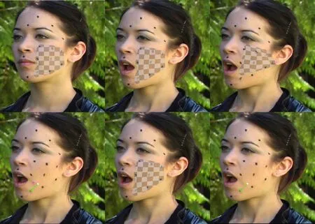
Fig.6 Correcting tracking errors caused by large displacements.Top left to bottom right:part of reference frame 1 with tracking region marked,frame 12 with tracking from reference still working,frame 13 with tracking directly from frame 1 failing,provision of a single correspondence as hint(green),correct tracking with additional hint,and estimated displacement vector for corrected point.
The remaining results in this section were created using production quality 4k footage that we are releasing as open test material alongside this publication.Thesailorsequence depicted in Fig.7 shows the flexing upper arm of a man.The post production task we defined was to stick a temporary tattoo onto the skin of the arm.A closeup of the effect is depicted below the samples.Note the strongly non-rigid deformation of the skin and therefore of the anchor overlay.Also note the change in shading on the skin;it is estimated and applied to the tattoo.The texture unwrap(without photometric compensation)in Fig.7 highlights how the complex lighting and surface characteristics lead to very different appearances of the skin throughout the sequence.While geometric alignment and photometric properties were estimated fairly accurately,the shifted difference images depicted in Fig.9 show a considerable texture differences.
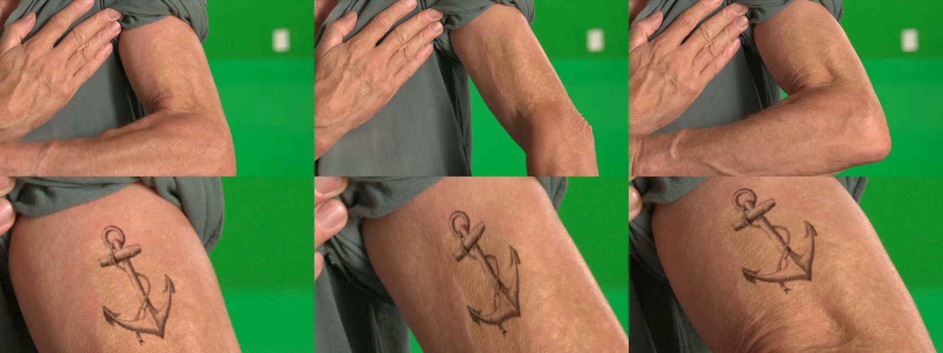
Fig.7 Samples from the sailor sequence(100 frames)and a closeup of the same samples including the visual effects.

Fig.8 Texture unwrap of the same samples as in Fig.7.

Fig.9 Shifted differences of the unwrapped samples in Fig.7 and the reference region.
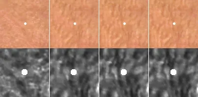
Fig.10 Problematic region in texture space and high contrast closeup for better assessment.

Fig.11 Closeup of a problematic tracking region in the final composite.
The reason is that estimation of photometric parameters is limited to smooth,low frequency shading properties and cannot capture fine details like shadows of the bulging skin pores in this example.However,on playing back the unwrappedsailorsequence,it can be observed that the overall surface stays fairly static,suggesting that the tracking result is adequate.Nevertheless,there is a distinct disturbance for a few frames in a con fined region of the image.Figure 10 shows from left to right the reference image,the unwrap just before the disturbance starts,the unwrapped frame of maximum drift,and the corrected version.A drifting structure exists as a vertical dark ridge passing through the overlayed reference point.The ridge drifts about 5 pixels to the right.As this feature cannot be distinguished in the reference image,we use an adjacent frame as reference for the correction.The issue can be solved with both the smoothness brush and the adjustment tool.Applying the smoothness brush is particularly easy,as the problematic region is very con fined and can just be covered by a small static matte in texture space.The adjustment tool can also easily be applied in a single frame in texture space and the corrected result can be propagated to eliminate the drift in all affected frames.As there is considerable global motion in the sequence and the issue is very con fined and subtle,we found that assessment and interaction in texture space is the only effective and efficient way to detect,quantify,and solve the problem.
Thewifesequence depicted in Fig.12 shows a woman lifting her head and wiping hair out of her face.The post-production task we defined was to age her by painting wrinkles on her face.The final effect is depicted below the samples.Note the opening of the mouth and eyes,the occlusion by the arm,and the change in facial expression.Good initial results can be achieved for the tracking of the skin.However,the opening of the mouth,the blinking of the eyes,and the motion of the arm create considerable problems.Due to the confinement of the disturbance,both the influence and the smoothness brush can be applied for the mouth and the eyes.See Fig.5 for a similar use-case.In this specific case,an adjustment of the global smoothness parameterλLadequately solved the issue.One distinct problem to be solved is the major occlusion by the wife’s arm where she is wiping the hair out of her face.To have an unoccluded reference texture,tracking was started at the last frame and performed backwards.Figure 13 highlights that while most of the sequence tracks perfectly well,at the end of the sequence major disturbances occur.To solve this problem,the influence brush is applied in texture space.For this,we used the built-in Roto tool in NUKE with only 5 keyframes. The resulting matte can be reused in compositing to limit the painted overlay to the surface of the face.Figure 14 illustrates application of the influence brush to two problematic frames.Note the improvements around the mouth and on the cheek.

Fig.12 Samples from the wife sequence(100,8,and 1)and the same samples including the visual effect.
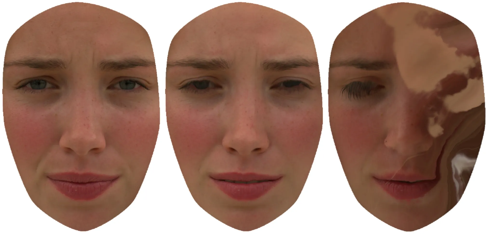
Fig.13 Unwrapped samples of the wife sequence(100,50,and 1).
In order to evaluate the effectiveness of the proposed tool sand work flows,post-production companies compared the NUKE plugin tool with other existing commercialtools in real-world scenarios. Different usability criteria were rated on a 5-point scale and passed back together with additional comments.The resulting feedback showed that the proposed method was rated superior to the other tools.Most criteria were judged slightly better while “usefulness”and “overall satisfaction”were rated clearly higher,indicating that consideration of user hints in deformable tracking can enhance real visual effects work flows.
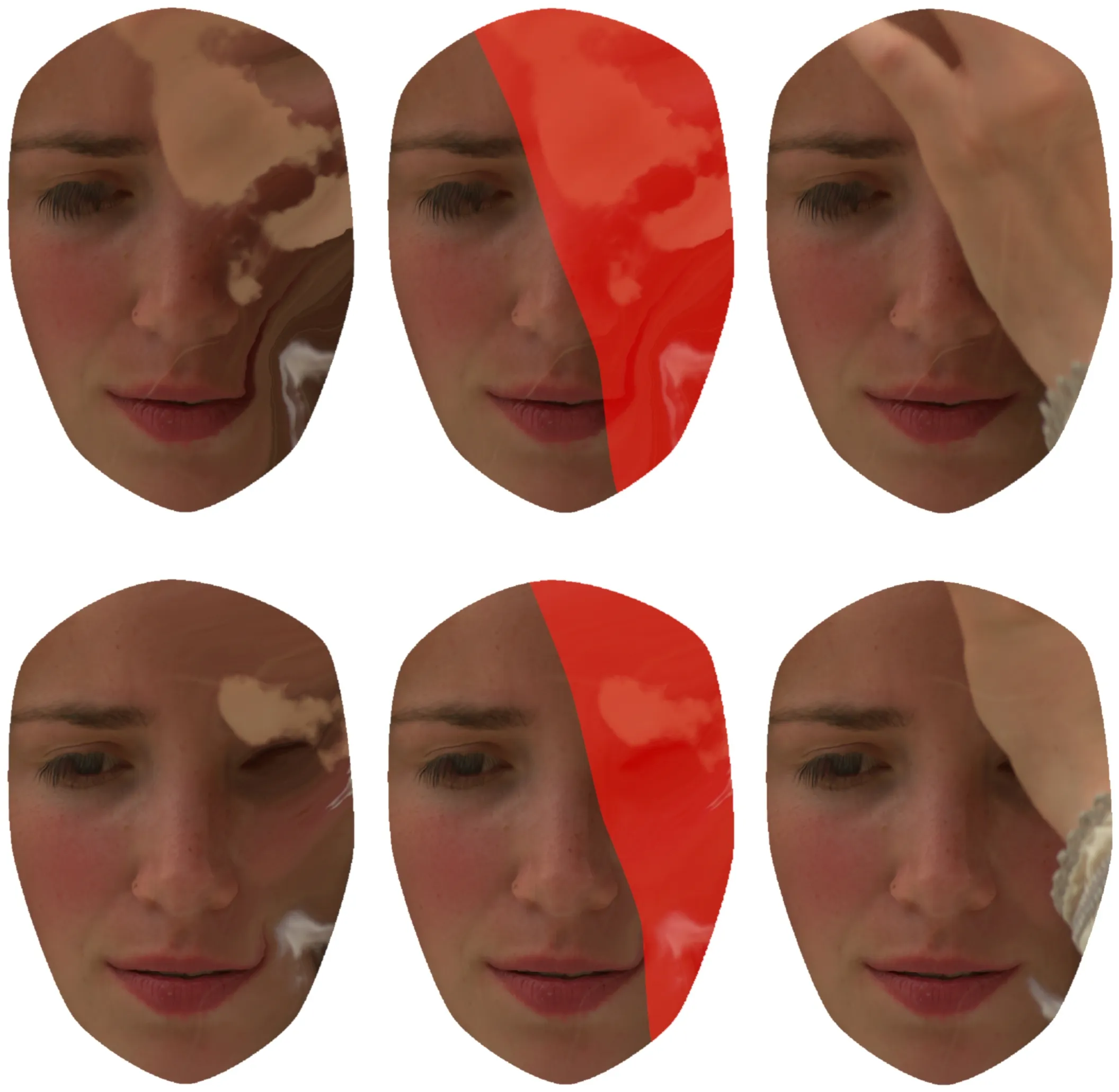
Fig.14 Texture unwrap of samples 8 and 1 of the wife sequence,application of the influence brush in texture space,and resulting tracking improvement.
6 Conclusions
We have introduced a novel way of assessing and interacting with surface tracking results and algorithms based on unwrapping a sequence to texture space.To prove applicability to the relevant use-cases,we have implemented our approach as a plugin for an established post-production platform.Assessing the quality of tracking results in texture space is equivalent to detecting geometric(and photometric)changes in a played back sequence.We found that this is a simple task even for an untrained casual observer and that established post production tools can help to pinpoint even minimal errors. Therefore,assessment has proven to be very effective.The application of user interaction tools directly in texture space in combination with iterative re-optimization of the result has proven to be intuitive and effective.The most striking benefits of applying tools in texture space is that interaction can be focused on a very localized area and that only small cursor movements are required to correct errors.We believe that there is a high potential in pursuing both research and development in texture space assessment and user interaction for tracking applications.
Acknowledgements
This work was partially funded by the German Science Foundation(Grant No.DFG EI524/2-1)and by the European Commission(Grant Nos.FP7-288238 SCENE and H2020-644629 AutoPost).
Electronic Supplementary Materiall Supplementary material is available in the online version of this article at http://dx.doi.org/10.1007/s41095-017-0089-1.
References
[1]Imagineer Systems.mocha Pro.2016.Available at http://www.imagineersystems.com/products/mochapro.
[2]Foundry.NUKE.2016.Available at https://www.foundry.com/products/nuke.
[3]The Pixelfarm.PFTrack.2016.Available at http://www.thepixelfarm.co.uk/pftrack/.
[4]Klose,F.;Ruhl,K.;Lipski,C.; Magnor,M.Flowlab—An interactive tool for editing dense image correspondences.In:Proceedings of the Conference for Visual Media Production,59–66,2011.
[5]Ruhl,K.;Eisemann,M.;Hilsmann,A.;Eisert,P.;Magnor,M.Interactive scene fl ow editing for improved image-based rendering and virtual spacetime navigation.In: Proceedingsof the23rd ACM International Conference on Multimedia,631–640,2015.
[6]Zhang,C.;Price,B.;Cohen,S.;Yang,R.Highquality stereo video matching via user interaction and space–time propagation.In:Proceedings of the International Conference on 3D Vision,71–78,2013.
[7]Re:Vision Effects. Twixtor. 2016. Available at http://revisionfx.com/products/twixtor/.
[8]Wilkes,L.The role of ocula in stereo post production.Technical Report.The Foundry,2009.
[9]Chrysos,G.G.;Antonakos,E.;Zafeiriou,S.;Snape,P.Offline deformable face tracking in arbitrary videos.In:Proceedings of the IEEE International Conference on Computer Vision Workshops,1–9,2015.
[10]Rother,C.;Kolmogorov,V.;Blake,A. “GrabCut”:Interactive foreground extraction using iterated graph cuts.ACM Transactions on GraphicsVol.23,No.3,309–314,2004.
[11]Liao,M.;Gao,J.;Yang,R.;Gong,M.Video stereolization:Combining motion analysis with user interaction.IEEE Transactions on Visualization&Computer GraphicsVol.18,No.7,1079–1088,2012.
[12]Wang,O.;Lang,M.;Frei,M.;Hornung,A.;Smolic,A.;Gross,M.Stereobrush:Interactive 2D to 3D conversion using discontinuous warps.In:Proceedings of the 8th Eurographics Symposium on Sketch-Based Interfaces and Modeling,47–54,2011.
[13]Doron,Y.;Campbell,N.D.F.;Starck,J.;Kautz,J.User directed multi-view-stereo.In:Computer Vision–ACCV 2014 Workshops.Jawahar,C.;Shan,S.Eds.Springer Cham,299–313,2014.
[14]Bartoli,A.;Zisserman,A.Direct estimation of nonrigid registrations.In:Proceedings of the 15th British Machine Vision Conference,Vol.2,899–908,2004.
[15]Zhu,J.;Van Gool,L.;Hoi,S.C.H.Unsupervised face alignment by robust nonrigid mapping.In: Proceedings of the IEEE 12th International Conference on Computer Vision,1265–1272,2009.
[16]Hilsmann,A.;Eisert,P.Joint estimation of deformable motion and photometric parameters in single view videos.In:Proceedings of the IEEE 12th International Conference on Computer Vision Workshops,390–397,2009.
[17]Gay-Bellile,V.;Bartoli,A.;Sayd,P.Direct estimation of nonrigid registrations with image-based self occlusion reasoning.IEEE Transactions on Pattern Analysis&Machine IntelligenceVol.32,No.1,87–104,2010.
[18]Seibold,C.;Hilsmann,A.;Eisert,P.Model-based motion blur estimation for the improvement of motion tracking.Computer Vision and Image UnderstandingDOI:10.1016/j.cviu.2017.03.005,2017.
[19]Hilsmann,A.;Schneider,D.C.;Eisert,P.Image-based tracking of deformable surfaces.In:Object Tracking.InTech,245–266,2011.
[20]Pilet,J.;Lepetit,V.;Fua,P.Real-time nonrigid surface detection.In: Proceedings of the IEEE Computer Society Conference on Computer Vision and Pattern Recognition,Vol.1,822–828,2005.
[21]Brox,T.;Malik,J.Large displacement optical fl ow:Descriptor matching in variational motion estimation.IEEE Transactions on Pattern Analysis and Machine IntelligenceVol.33,No.3,500–513,2011.
[22]Wedel,A.;Cremers,D.;Pock,T.;Bischof,H.Structure-and motion-adaptive regularization for high accuracy optic fl ow.In:Proceedings of the IEEE 12th International Conference on Computer Vision,1663–1668,2009.
[23]Brox,T.;Bruhn,A.;Papenberg,N.;Weickert,J.High accuracy optical fl ow estimation based on a theory for warping.In:Computer Vision–ECCV 2004.Pajdla,T.;Matas,J.Eds.Springer Berlin Heidelberg,25–36,2004.
[24]Hollywood Camera Work.Face Capture dataset.2016.Available at https://www.hollywoodcamerawork.com/tracking-plates.html.
猜你喜欢
杂志排行
Computational Visual Media的其它文章
- Photometric stereo for strong specular highlights
- Image editing by object-aware optimal boundary searching and mixed-domain composition
- Adaptive slices for acquisition of anisotropic BRDF
- Transferring pose and augmenting background for deep human image parsing and its applications
- Robust edge-preserving surface mesh polycube deformation
- A 3D morphometric perspective for facial gender analysis and classification using geodesic path curvature features
