Research on the Low-order Control Strategy of the Power System With Time Delay
2018-05-02XinyiYuXuejinfengHongJunQiLinlinOuandYanlinHe
Xinyi Yu,Xuejinfeng Hong,Jun Qi,Linlin Ou,and Yanlin He
I.INTRODUCTION
WITH the interconnection of the power grids,the size of power systems becomes larger,and the operation condition becomes more variable.The emergence of the wide-area measurement systems(WAMS)provides new opportunities for the analysis and control of wide-area power systems[1].There unavoidably exists the time delay in the interconnected power system.If the time delay is large,it can significantly change the dynamic characteristics of the power system,such as the oscillation mode and critical eigenvalues of the system[2],[3].The time delay cannot be neglected when the data of the wide-area measurements are adopted as the output feedback signals of the damping controller[4]-[7].It is important to analyze the stability of the time-delay power systems and to propose an effective controller design method in order to avoid the instability of the power angle.
At present,the structures of the wide-area time-delay damping controllers in the power systems are divided into two types:the state-space structure based on the state feedback control and the transfer-function structure based on the leadlag link[8]-[15].Since the state space model of the actual wide-area power system is high order and the elapsed time of the controller parameter solution based on the linear matrix inequality(LMI)technology is long,the order of the power system model needs to be reduced[8].If the controller is in the form of the state feedback,an additional state observer design is required to compensate the effect of the time delay[8],[9].The second structure of the damping controllers can improve the damping capacity of the power system by adjusting the parameters of the lead-lag phase.For the time delay of the phasor measurement unit(PMU),the delay compensation is employed to predict the real-time control signal so as to compensate the effect of the time delay.By using the Pade approximation,the time delay can be transformed into a part of the transfer function model of the power system[10],[11].Therefore the controllers can be designed according to the conventional control method without time delay[12].However,the critical characteristic parameters which are required for the parameters tuning cannot be obtained predictively in the actual power system.Furthermore,there are few applications of proportional-integral-differential(PID)controllers in the field of low frequency oscillation damping control of power systems.
It is well known that the simple low-order controllers,especially PID controllers,are widely used in various engineering application fields.The traditional parameter tuning methods are mainly based on empirical formula.Up to now,various PID tuning methods have been proposed for continuous time linear systems with time delay[16]-[22].A lot of research results have been presented to determine the stabilizing regions of PID parameters[23]-[29].It is difficult for the existing PID design theory to take the accuracy index,the fast index and the robust index of the system into account simultaneously during the design process.
In order to flexibly consider multi performance indexes,the problem of stabilizing a power system with a fixed time delay using a low-order controller is considered in this paper.A linear model of the power system with time delay is established in this paper to analyze the stability of the power system.Then a PID controller is designed to improve the performance of the power system.The stability of the power system is guaranteed by the parameters in the stabilizing domain of the PID controller.Then,the PID controller which satisfies theH∞performance index is designed and it improves the robus-tness of the whole power system.According to different performance requirements of the system,the parameters of the PID controller can be directly obtained.
The paper is organized as follows.The linear model of the power system is established in Section II.In Section III,the algorithm for determining the stabilizing set of the PID controller for time-delay power system is proposed.In Section IV,the performance requirement of the power system with time delay and the method for obtaining the parameters set satisfying the performance index are given.A numerical example is presented to check the validity of the proposed method in Section V.Finally,Section VI provides some concluding remarks.
II.THE MODELING OF POWER SYSTEMS WITH TIME DELAY
Because of the relative size of the power system to which the generator supplies power,the dynamics associated with the generator virtually cause the change of the voltageUand the frequencyf.Such a voltage source with constant voltage and frequency can be seen as an in finite bus.For any given system conditions,the magnitude of the in finite bus voltageUremains constant when the machine is perturbed.
Before obtaining the model of the power system with time delay,the definition of the symbols are given in Table I.The variables are assumed to be in per unit.The subscript 0 denotes the initial value.The deviation vector is denoted as Δ.

TABLE IRELATIVE SYSTEM PARAMETERS
The linear model of the single-machine in finite bus(SMIB)system is the foundation of the mechanism research on dynamic stability.With all resistances neglected,the SMIB system is shown in Fig.1.Its magnitude is assumed to remain constant at the pre-disturbance value.The model of the generator in thed-qcoordinate system is as follows:

wherePe=()IdIq.The excitation system is described by a first-order inertia model,which is represented byKeandTe.According to the transfer function of the excitation system in Fig.2[30],we have


Fig.1. Diagram of the single machine in finite bus system.
In Fig.2,Urefis a constant.In thex-ycoordinate system,the equation of the network isUt∠θ-U∠0°=jXI∠φ.SetUx+jUy=Ut∠θandIx+jIy=I∠φ.The real and imaginary parts of the network equation can be separated,which is given by


Fig.2. Transfer function of the excitation system in the single machine in finite bus system.
In addition,from the transform relationship between of thed-qcoordinate system and thex-ycoordinate system shown in the Fig.3,we have

wherefisUorI.
The mathematical model of the whole power system is presented by(1)-(4),and it is four order if the governor dynamic is ignored.ω,δ,E′qandEfare the state variables.
If the algebra variables of(1)-(4)are eliminated and the equations are linearized at the work point,the incremental equations can be translated into the state quantities.The detailed steps are as follows:
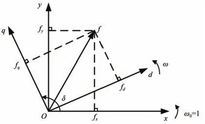
Fig.3. Transform relationship between of the d-q coordinate system and the x-y coordinate system.
Step 1:According to the relationship of thedq-xycoordinate system,transform the coordinate system of the network equations to thed-qcoordinate system.Then determine the expressions ofUd,Uq,IdandIqwith respect toE′qandδ.After that,transfer these quantities into incremental forms.
Step 2:Linearize the differential equations of the generator,where the algebraic quantities are eliminated according to the results of Step 1.
Step 3:Present the linear model of the whole system by going through the same operations to the differential equations of the excitation system.
Premultiply both sides of(3)byand convert the result into thed-qcoordinate system according to(4).Then the following network equation is obtained.


By combining(5)with(1),the expressions ofIq,Id,UdandUqin(6)(show at the bottom of this page)is derived.The corresponding incremental equations are
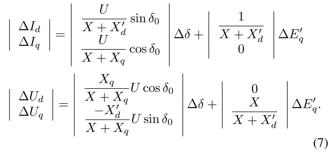
The differential equations of the generator which are in the last three items of(1)can be transformed as


where ΔPeand ΔEqare the algebraic quantities.According to(1)and the expression ofPe,ΔPeand ΔEqcan be transformed into the equations with respect to ΔId,ΔIq,ΔE′q

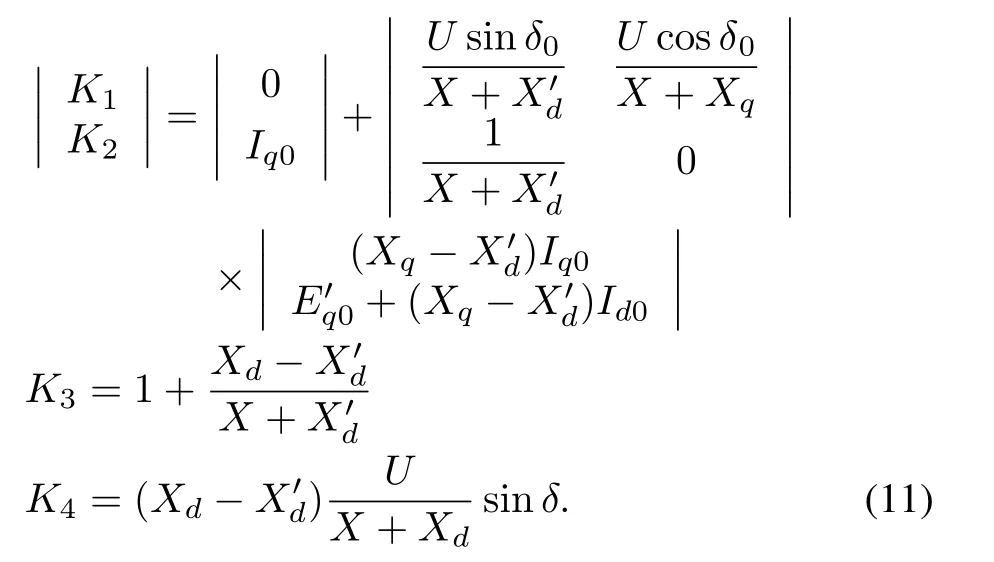
Substituting(7)into(9)and eliminating ΔIdand ΔIqyield

whereK1,K2,K3andK4are given by
In addition,the incremental equations of the excitation system described by(2)are transformed to

where

According to(7),we have

Equations(7),(8),and(10)-(14)compose the linear model of the whole system.In summary,the control block diagram of the linear model for the SMIB system is shown in Fig.4.The input of the system is ΔPmand the output of the system is Δδ.By using the fast valving method,the value of ΔPmcan be adjusted.The operation parameters are got from the numerical work point.ωN=2πf,where is the frequency of the power system.The transfer function in Fig.4 is given by

Fig.4.Linear model of single machine in finite bus system.

where

Considering the time delay,the transfer function of the model is

whereτrepresents the time delay.De fineN(s)andD(s)as

III.METHOD OF DETERMINING THE STABILIZING SET OF PID CONTROLLER SET FOR THE POWER SYSTEM WITH TIME DELAY
In order to improve the performance of the power system with time delay,a PID controller is designed.According to the resultant model of the power system in Section II,the block diagram of the unit feedback control system is shown in Fig.5.In Fig.5,G(s)is the transfer function of the power system presented in(16)andC(s)=kp+ki/s+kdsis the low-order controller,wherekp,kiandkdare the proportional,integral and derivative parameters,respectively.Based on the stability analysis method of the Nyquist curve,the problem of solving the characteristic roots of the system with time delay can be avoided.

Fig.5. Block diagram of unit feedback control system.
Substitutings=jz/τinto(17)and(18),we haveN(jz/τ)=-b2z2/τ2+b0+jb1z/τ,D(jz/τ)=z4/τ4-a2z2/τ2+a0+j(-a3z3/τ3+a1z/τ),wherezis real.De fineq(z,kp),q1(z)andp1(z)as
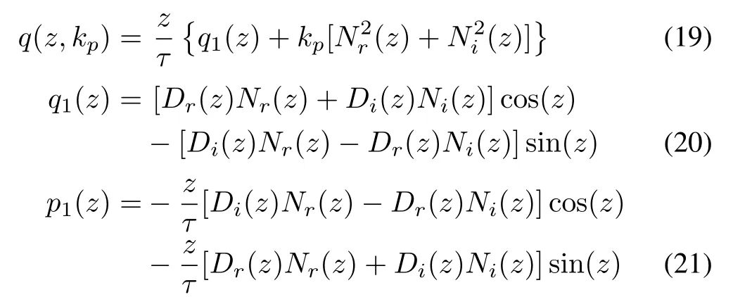
whereDr(z),Di(z),Nr(z)andNi(z)are the real and imaginary parts ofD(jz/τ)andN(jz/τ),respectively.
Based on the results in[23],the stabilizing set of the PID controller can be obtained by using the following theorems.
Theorem 1:Assume thatQis the number of the intersections of the linef1(z)=kpand the curvef2(z)=-q1(z)/[N2r(zt)+N2i(zt)]in(0,Z),whereZ=2l∗πandl∗is a sufficiently large integer.The necessary condition for thekpvalue leading to the existence of the stabilizing range of(ki,kd)is that the following equation must hold.

wherel(N),r(N)andj(N)are the numbers of the zeros ofN(s)on the left half plane,the right half plane and the positive imaginary axis,respectively.
LetZ=2l∗π,0=z0<z1<z2<···<zc-1be the real and distinct zeros in[0,Z]ofq(z,kp),andzc=Z.The signatureγ(I)is denoted byγ(I)={i0-2i1+2i2+···+(-1)c-12ic-1}·(-1)c-1sgn[q(z+c-1)].
Theorem 2:Consider the PID stabilization of a given SISO LTI plant with transfer functionG(s).For a fixedkp,if there exists one stringI={i0,i1,...}satisfyingγ(I)=4l∗+5-[l(N)-r(N)],then the stabilizing region of(kd,ki)is the intersection of the following inequalities

for∀t=0,1,2,...,leading toN(jzt/τ)/=0.HereA(zt)=2andB(zt)=p1(zt)/[(zt)+(zt)].If the stringsI1,I2,...,Ihall satisfyγ(I)=4l∗+5-[l(N)-r(N)],then the stabilizing set of(kd,ki)satis fies(22)forI1,I2,...,Ih.
The steps of obtaining the stabilizing set of(kp,ki,kd)for the power system with time delay can be summarized as follows:
Step 1:Choose a large enough value ofl∗and letZ=2l∗π.
Step 2:Determine the range ofkpover which the gridding needs to be carried out by using Theorem 1.
Step 3:Gridkpwithin the range obtained in Step 2.
Step 4:For a grid pointkp,compute the real and distinct zeros ofq(z,kp)in the interval.Then denote them byz0,z1,z2,...,zc-1in ascending order and takezc=Z.
Step 5:Examine whetherN(-jzt/τ)equals to zero for somet=0,1,2,3,...,candN(-s)has a zero at the origin.Letit=0 ifN(-jzt/τ)=0 for somet=0,1,2,3,...,cand takehas a zero at the origin,wherep1(z)is given by(21).Otherwise,letit=1 or-1.

Step 6:Under the constraint foritgiven in Step 5, findI={i0,i1,...,ic-1}satisfying the following equation.Step 7:If obtained in Step 6 is unique,present the stabilizing set of(kd,ki)by computing the intersection of the inequalities determined by(23)with respect toI.IfIis not unique,the stabilizing set of(kd,ki)is the union of stabilizing regions of(kd,ki)determined by(22)for all strings satisfying(23).
Step 8:Go to Step 4 with another grid point ofkptill all the grid points are considered.
IV.PID CONTROLLER PARAMETER OPTIMIZATION FOR THE POWER SYSTEM WITH TIME DELAY
There may be a risk of low frequency oscillation in the power system with time delay.To ensure the stabilizing operation of the system,the damping ratio of the system must meet certain requirements.Because of the existence of the time delay in the system,it is very difficult to solve out the complex eigenvalue.It is not suitable to choose the damping ratio of system as the performance index.Here we use the overshoot instead of damping ratio as the performance index of the system.The stabilizing region of the power system with time delay can be calculated by the method described in Section III.Based on such the stabilizing region,the set of controller parameters can be found in the stabilizing region in accordance with the required performance.
A.Performance Requirement of the Power System With Time Delay
Low damping or negative damping in power system will lead to low frequency oscillation[3].It will be a serious threat to the stabilizing operation of the whole system.Therefore,we must consider the damping ratio in the controller design process.When the damping ratio is larger than 10%,the power system has good stability[31],[32].The damping ratio is given by

for a pair of complex eigenvalues:

Because of the existence of the time delay in the system,it is very difficult to solve out the complex eigenvalue of the power system.It is not suitable to choose the damping ratio of system as the performance index.From the relationship curve of the overshoot and the damping ratio shown in Fig.6[31],it is seen that the damping ratio of the system is roughly inversely proportional to the overshoot.Since overshoot can be directly obtained from the response curve,the overshoot is chosen as the performance index of the system.According to Fig.6,it is obtained that the damping ratio is larger than 10%when the overshootσis less then 0.67.Thus,the performance requirement of the power system isσ<0.67.
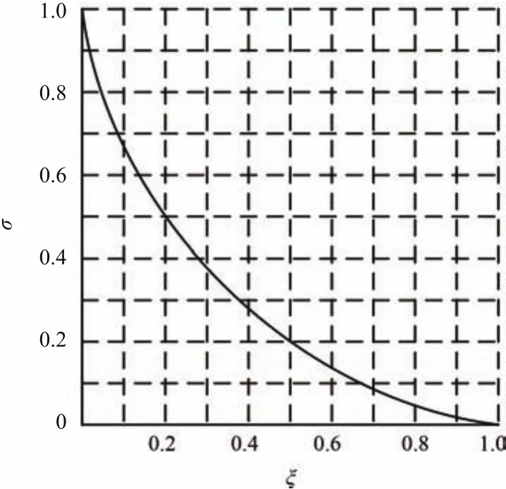
Fig.6.Relationship curve of the damping ratio ζ and the σ.
B.Design of H∞PID Controller
From Section III,it is known that if the value ofkpis fixed,the stabilizing region of(kd,ki)has the characteristics of linear programming.For the linear time-delay system,the stabilizing region of the PID controller is presented based on the Hermite-Biehler theorem.The values of the control parameters chosen in such the region can guarantee the stability of the power system with time delay.
Based on the property of the stabilizing PID controller,the control parameters that satisfy theH∞performance index‖W(s)T(s,kp,ki,kd)‖∞<µis designed so as to improve the robustness of the power system.When theH∞performance index is satisfied,the power system with the PID controller has good robustness.Then the control parameters which satisfy the overshootσ<0.67 in the PID control parameter region is chosen.Here,µ >0 is a pre-specified constant,W(s)is the weight function andT(s,kp,ki,kd)is the complementary sensitivity function,where

Let the weighting functionW(s)=Wn(s)/Wd(s),whereWn(s)andWd(s)are coprime polynomials.AndWd(s)is stable.MultiplyingW(s)by both sides of(26),we have

The weight functionW(s)is set asvskip0.1mm

Based on the results in[16],the PID parameter domain which satisfies theH∞performance index of the power system can be obtained in terms of the following algorithm[33]:
Step 1:According to[16],determines the stabilizing range of the parameterkp.
Step 2:Pick up a grid point ofin the stabilizing range of the parameterkp.
Step 3:In terms of Theorem 7 in[16],present the stabilizing region of(kd,ki)which makesδ(s,kp,ki,kd)stable and denote it asS(1,k∗p),whereδ(s,kp,ki,kd)=sD(s)eτs+(kds2+kps+ki)N(s).
Step 4:For a certain value ofφ∗,setυ(s,kp,ki,kd,φ)=L(s)eτs+(kds2+kps+ki)M(s),whereL(s)=sD(s)Wd(s)andM(s)=N(s)[Wd(s)+ejφ∗Wn(s)/µ].By using Theorem 7 in[16]and solving a linear programming problem,present the set of(kd,ki)for whichυ(s,kp,ki,kd,φ∗)is stable and denote it asS(2,k∗p,φ∗).Then,by sweeping overφ∈[0,2π),determine the set of(kd,ki)such that eachυ(s,kp,ki,kd,φ∗)is stable,and denote it asS(2,k∗p)=∩φ∈[0,2π)S(2,k∗p,φ∗).
Step 5:Present the admissible set of(kd,ki)for which fand denote it asS(3,).
Step 6:Determine the entire set(kd,ki)for whichby finding the intersection of
Step 7:Return to step 2 with another grid point ofkptill all the grid points are considered.Determine the set(kp,ki,kd)satisfying‖W(s)T(s,kp,ki,kd)‖∞<µ.
Step 8:Find the control parameters satisfyingσ<0.67 in the set(kp,ki,kd)obtained in Step 7.
V.SIMULATION
In order to verify the proposed method,the following group of SMIB system is taken for example.
The single-line diagram of the power system is given in Fig.7.The frequency of the system reference is 50Hz.

Fig.7.Diagram of the SMIB system.
The system parameters are presented as follows:δ=36°,Xd=1.81,=0.3,X=0.65,Xq=1.76,Iq=0.411,Id=0.856,U=0.955,Ut0=1.0,Uq=0.696,Ud=0.718,E′q=0.726,D=0,ωN=100π,Tj=5s,T′d0=8.940s,Ke=200,Te=0.050s.
Substituting the above values into(11)and(14)yields:K1=1.0293,K2=1.0426,K3=2.6413,K4=0.9599,K5=0.5506,K6=0.4762.Then substituting the value ofK1,K2,K3,K4,K5andK6into(15),we have

Taking the time-delay value as 0.1,the transfer function of the SMIB system is

According to Theorem 1,the range ofkpis(0.154,1.480).In terms of(19)and(20),we haveq(z,kp)=z[q1(z)+kp(39690000z4-10800900z2+18931008)],whereq1(z)= (-63000000z6+57496000z4-210536060z2+ 29140186.1)cos(z)-(-390000z5-157000z3-206640729z)sin(z).The value ofl∗is chosen to be 2,which leads toZ=12.5664.Following the procedure of computing the stabilizing range ofkp,the range ofkpover which the gridding needs to be carried out is from 0.154 to 1.480.Next,we determine the stabilizing region of(kd,ki)for a value ofkpchosen from(0.154,1.480).For example,kpis chosen as 0.5.Whenkp=0.5,we haveq(z,0.5)=z[(-630000000z6+574960000z4-2105360600z2-291401861)cos(z)-(-3900000z5-1570000z3-2066407290z)sin(z)+198450000z4-54004500z2+946550405].Then the real and distinct zeros ofq(z,0.5)in[0,12.5664)arez0=0,z1=0.4190,z2=1.6520,z3=4.7297,z4=7.8497,z5=10.9988,z6=Z=12.5664.According to Steps 4 and 5,we can determine the stringIsatisfying(23).In the light of Theorem 2,the string{i0,i1,i2,i3,i4,i5}has to satisfy(i0-2i1+2i2-2i3+2i4-2i5)·(-1)5sgn[q(z+5)]=11.It follows that:I={i0,i1,i2,i3,i4,i5}={1,-1,1,-1,1,-1}.Then from Step 6,it is concluded that the stabilizing(kd,ki)corresponding tokp=0.5 have to simultaneously satisfy the following inequalities.

From these inequalities,the stabilizing region of(kd,ki)is sketched,which is shown in Fig.8.By using Steps 3-6 for eachkpvalue in(0.154,1.480)repeatedly,the stabilizing set of(kp,kd,ki)is obtained.The stabilizing set of(kp,kd,ki)is shown in Fig.9.Whenkp=0.5,ki=0.5 andkd=0.1,the response curve of the system is presented in Fig.10.From Fig.10,it is seen that the system is stable.According to the performance requirement of the power system with time delay in Section IV,the design requirement is met.Whenkp=0.5,ki=5 andkd=0.1,the response curve of the power system is shown in Fig.11.Since(kp,ki,kd)=(0.5,5,0.1)does not
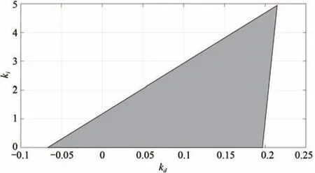
Fig.8. Stabilizing range of(kd,ki)when kp=0.5.
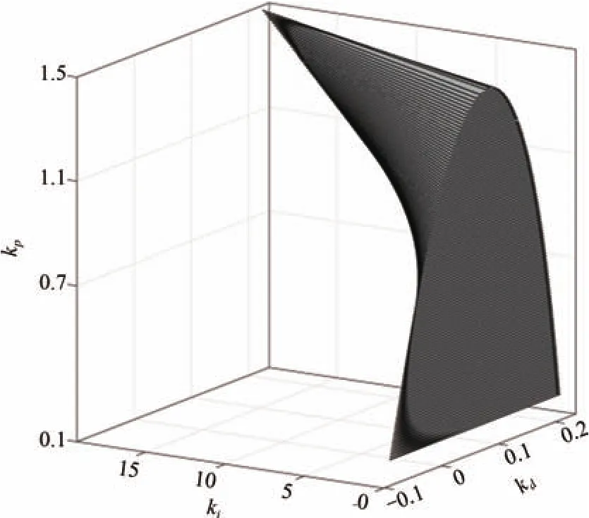
Fig.9. Stabilizing region of the power system with time delay.
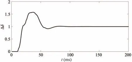
Fig.10.Response curve of the system when kp=0.5,ki=0.5 and kd=0.1.
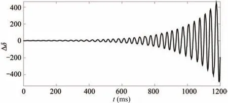
Fig.11.The response curve of the system when kp=0.5,ki=5 and kd=0.1.

Fig.12. PID controller parameter domain satisfying|W(s)T(s,kp,ki,kd)|∞<1 when kp=0.5.
lie in the stabilizing region given in Fig.9,the system is unstable.According to the algorithm given in Section IV,whenkp=0.5,the PID controller parameter domain satisfying‖W(s)T(s,kp,ki,kd)‖∞<1 is shown in Fig.12.We choose(kp,ki,kd)=(0.5,0.2,0.06)from the PID controller parameter domain.When the time delay changes,the response curves of the system is shown in Fig.13.The overshoots of the power system with different time delays corresponding to(kp,ki,kd)=(0.5,0.2,0.06)are all less than 0.5.Thus the design requirement is satisfied and good robustness of the power system is obtained.

Fig.13.Response curves of the system when kp=0.5,ki=0.2 and kd=0.06.
VI.CONCLUSION
The design method of the PID controller is proposed to control the power system with time delay in this paper.The algorithm to determine the stabilizing set of the PID controller for the power system with time delay is first presented.Based on the stability conditions,the PID controller satisfying theH∞performance index is then obtained to improve the robustness of the system.By choosing appropriate values in the resultant region of theH∞PID control parameters,the PID controller can also make the power system meet the performance requirement that the damping ratio is larger than 10%.Thus,according to different performance requirements of the system,the parameters of the PID controller can be obtained directly.The main advantage of the proposed method is that for the high-order power system,there is no need to approximate the model of the power system.Time delay and parameter tuning are two difficult problems that are encountered by the wide-area controller of the power system in engineering application.The results in this paper provides a new way to solve these problems.
[1]Q.Y.Jiang,Z.Y.Zou,Y.J.Cao,and Z.X.Han,“Overview of power system stability analysis and wide-area control in consideration of time delay,”Autom.Electr.Power Syst.,vol.29,no.3,pp.1-7,Feb.2005.
[2]F.Milano and M.Anghel,“Impact of time delays on power system stability,”IEEE Trans.Circuits Syst.I,vol.59,no.4,pp.889-900,Apr.2012.
[3]B.Yang,L.Wei,Z.Zhan,and J.Qi,“Analysis on the characteristics of communication delay in wide area measuring system based on probability distribution,”Autom.Electr.Power Syst.,vol.39,no.12,pp.38-43,Jun.2015.
[4]N.C.Chang,Z.Lan,D.Q.Gan,and Y.X.Ni,“A survey on applications of wide-area measurement system in power system analysis and control,”Power Syst.Technol.,vol.29,no.10,pp.46-52,May2005.
[5]J.Qi,“Time delay damping control of low frequency oscillation in power systems based on WAMs,”Ph.D.dissertation,Zhejiang University,Hangzhou,China,2009.
[6]H.X.Wu,H.Ni,and G.T.Heydt,“The impact of time delay on robust control design in power systems,”inProc.IEEE Power Engineering Society Winter Meeting,New York,NY,USA,vol.2,pp.1511-1516,2002.
[7]B.Chaudhuri,R.Majumder,and B.C.Pal,“Wide-area measurement-based stabilizing control of power system considering signal transmission delay,”IEEE Trans.Power Syst.,vol.19,no.4,pp.1971-1979,Nov.2004.
[8]J.Qi,Q.Y.Jiang,and Y.J.Cao,“Design of damping controller for inter-area low-frequency oscillation using time-delay wide-area measurements,”Trans.China Electrotech.Soc.,vol.24,no.6,pp.154-159,Jun.2009.
[9]Z.Y.Zhang,Z.J.Hu,and Y.K.Liu,“Additional robust damping control of large scale DFIG-based wind power generation system with wide-area signals’time-varying delay in fl uence,”Trans.China Electrotech.Soc.,vol.29,no.4,pp.246-255,Apr.2014.
[10]Z.Fang,C.Lin,L.Xiong,Y.Z.Sun,and G.Chen,“Prediction based on hierarchical compensation for delays of wide-area closed-loop control systems,”Proc.CSEE,vol.34,no.19,pp.3194-3201,Jul.2014.
[11]Y.H.Liu,X.Li,Z.X.Liu,Y.Z.Sun,and Q.L.Zhou,“A compensation design for wide-area power system stabilizer distributed time delay based on grey prediction,”Autom.Electr.Power Syst.,vol.39,no.12,pp.44-49,Jun.2015.
[12]M.E.Aboul-Ela,A.A.Sallam,J.D.McCalley,and A.A.Fouad,“Damping controller design for power system oscillations using global signals,”IEEE Trans.Power Syst.,vol.11,no.2,pp.767-773,May 1996.
[13]J.Qi,Q.Y.Jiang,G.Z.Wang,and Y.J.Cao,“Wide-area time-delay robust damping control for power system,”Eur.Trans.Electr.Power,vol.19,no.7,pp.899-910,Oct.2009.
[14]H.Gulizhati and J.Wang,“Wide-area time-delay damping control of generalized Hamilton multi-machine power system,”Proc.CSEE,vol.34,no.34,pp.6199-6208,Dec.2014.
[15]S.B.Wang,X.Y.Meng,and T.W.Chen,“Wide-area control of power systems through delayed network communication,”IEEE Trans.Control Syst.Technol.,vol.20,no.2,pp.495-503,Mar.2012.
[16]L.L.Ou,W.D.Zhang,and L.Yu,“Low-order stabilization of LTI systems with time delay,”IEEE Trans.Autom.Control,vol.54,no.4,pp.774-787,Apr.2009.
[17]L.L.Ou,“Research on stabilization and design of low-order controllers for linear systems with time delay,”Ph.D.dissertation,Shanghai Jiao Tong University,Shanghai,China,2006.
[18]K.J.Astrom,C.C.Hang,and B.C.Lim,“A new Smith predictor for controlling a process with an integrator and long dead-time,”IEEE Trans.Autom.Control,vol.39,no.2,pp.343-345,Feb.1994.
[19]D.E.Rivera,M.Morari,and S.Skogestad,“Internal model control:PID controller design,”Ind.Eng.Chem.Process Des.Dev.,vol.25,no.1,pp.252-265,Jan.1986.
[20]W.K.Ho,C.C.Hang,and L.S.Cao,“Tuning of PID controllers based on gain and phase margin specification,”Automatica,vol.31,no.3,pp.497-502,Mar.1995.
[21]L.L.Ou,D.Y.Gu,and W.D.Zhang,“Optimal tuning method of PID controller based on gain margin and phase margin,”Control Theory Appl.,vol.24,no.5,pp.837-840,Oct.2007.
[22]R.Toscano,“A simple robust PI/PID controller design via numerical optimization approach,”J.Process Control,vol.15,no.1,pp.81-88,Feb.2005.
[23]N.Tan,“Computation of stabilizing PI and PID controllers for processes with time delay,”ISA Trans.,vol.44,no.2,pp.213-223,Apr.2005.
[24]L.H.Keel and S.P.Bhattacharyya,“Controller synthesis free of analytical models:Three term controllers,”IEEE Trans.Autom.Control,vol.53,no.6,pp.1353-1369,Jul.2008.
[25]N.Hohenbichler,“All stabilizing PID controllers for time delay systems,”Automatica,vol.45,no.11,pp.2678-2684,Nov.2009.
[26]Z.P.Zeng,Z.Q.Chen,and Z.Z.Yuan,“A method to determine the admissible set of PID controller parameters with robust performance,”Control Decis.,vol.20,no.4,pp.382-387,Apr.2005.
[27]G.J.Silva,A.Datta,and S.P.Bhattacharyya,“PI stabilization of firstorder systems with time delay,”Automatica,vol.37,no.12,pp.2025-2031,Dec.2001.
[28]G.J.Silva,A.Datta,and S.P.Bhattacharyya,“New results on the synthesis of PID controllers,”IEEE Trans.Autom.Control,vol.47,no.2,pp.241-252,Feb.2002.
[29]G.Martelli,“Comments on “new results on the synthesis of PID controllers”,”IEEE Trans.Autom.Control,vol.50,no.9,pp.1468-1469,Sep.2005.
[30]Y.X.Ni,S.S.Chen,and B.L.Zhang,Theory and Analysis of Dynamic Power System.Beijing,China:Tsinghua University Press Co.,Ltd,2002.
[31]H.M.Yang,F.Li,and G.M.Liu,“Study on damping ratio of low frequency power oscillations in large power network,”Sci.Technol.Innov.Her.,no.36,pp.100,102,2008.
[32]W.Yao,L.Jiang,J.Y.Wen,Q.H.Wu,and S.J.Cheng,“Widearea damping controller of FACTS devices for inter-area oscillations considering communication time delays,”IEEE Trans.Power Syst.,vol.29,no.1,pp.318-329,Jan.2014.
[33]L.L.Ou,P.D.Zhou,W.D.Zhang,and L.Yu,“H∞robust design of PID controllers for arbitrary-order LTI systems with time delay,”inProc.50th IEEE Conference on Decision and Control and European Control Conference,Orlando,FL,USA,2011,pp.1884-1889.
杂志排行
IEEE/CAA Journal of Automatica Sinica的其它文章
- Decomposition Methods for Manufacturing System Scheduling:A Survey
- Nonlinear Bayesian Estimation:From Kalman Filtering to a Broader Horizon
- Vehicle Dynamic State Estimation:State of the Art Schemes and Perspectives
- Coordinated Control Architecture for Motion Management in ADAS Systems
- An Online Fault Detection Model and Strategies Based on SVM-Grid in Clouds
- An Adaptive RBF Neural Network Control Method for a Class of Nonlinear Systems
