Coordinated Control Architecture for Motion Management in ADAS Systems
2018-05-02TzuChiLinSiyuanJiCharlesDickersonSeniorandDavidBattersby
Tzu-Chi Lin,Siyuan Ji,,Charles E.Dickerson,Senior ,and David Battersby
I.INTRODUCTION
AUTOMOTIVE vehicle dynamics have been a subject of research for decades.Engineers seek to understand the dynamic behavior of vehicles under different driving conditions,such as moderate daily driving as well as emergency situations[1]-[3].One of the major causes of accidents is the driver’s lack of ability to remain in the correct lane due to inattention or fatigue.In order to prevent these types of accidents,advanced driver assistance systems(ADAS),such as land departure warning(LDW),lane keeping assistance(LKA)and lane changing assistance(LCA)have been developed.ADAS is one of the fastest growing areas in the automotive industry and has become an integral part of modern vehicle safety and driving comfort[4]-[8].Some of the most common ADAS systems used today include adaptive cruise control,collision warning and lane changing assistance.
ADAS systems can provide the driver with essential information or automate difficult tasks.Some systems are critical to the safety while others provide added convenience to increase comfort or efficiency.Each of the various types of ADAS systems in service today generally provide a unique feature for the user that is implemented through additional control of one of the vehicle’s systems,e.g.braking or steering.ADAS systems must not be regarded as a substitute for drivers but rather as a co-driver,even if direct involvement in some of the driving tasks is not required[9].
The lane changing maneuver is one of the critical actions that a driver performs while travelling.It can occur,for example,when merges take place during the transition from urban to highway driving,during which a temporary merge lane exists for the vehicles to rapidly enter.Drivers also change lanes to follow a preferred route to reach their destination,or to improve their driving experience or level of service.Current lane changing assistance systems usually provide two levels of warning.The first level is reserved for cautionary warnings,when the likelihood of a collision is relatively low.The second level is instead an imminent type of warning,when dangerous situations are more likely to occur[10].
In addition to control of the vehicle position,driving quality and vehicle handling stability are also important to both safety and comfort.New technologies,such as coordinated motion control,i.e.,a control mechanism that coordinates controllers to achieve a desired motion for the vehicle[11]-[14],are being investigated to improve vehicle operation.The handling quality of the vehicle can be enhanced by the use of control strategies[14]and a combination of vehicle dynamics and electronics,such as steering systems and braking systems.In[15],a steering and braking control architecture is implemented by a nested proportional-integral-derivative(PID)controller with two independent control loops for lane keeping and disturbance rejection for improved driving safety.Coordination of steering and individual braking control for yaw stability control was proposed in[16].Using physics based models;a control architecture was investigated that improved the vehicle stability by achieving faster convergence and reducing the impact on the longitudinal and lateral dynamics.Another example of the bene fits of joining vehicle dynamics with motion coordination is in controllable objects,such as those using independent controllers and actuators[17].A more advanced concept is currently under research and development by[18].This will enable the vehicle to drive without commands from the driver.
Active front steering(AFS)control systems provide an example of ADAS that has been widely utilized in automotive vehicles.Extensive academic research has been published over the past 15 years,for example[16],[19]-[21].AFS has an ability to improve the steering response and enhance the unstable handling situation.Due to the lateral tire force and tire slip angle,AFS is effective within the linear region when the lateral tire force is proportional to the corresponding slip angle.However,when the vehicle meets the handling limit and the lateral tire force is close to saturation point,AFS becomes less effective.Therefore,in order to maintain vehicle stability,coordinated dynamic stability control which uses the two independently developed controllers to produce the required corrective yaw moment and sideslip angle has also been developed[22]-[26].These can effectively minimize the interaction between the two systems,such as steering and braking systems.The advantage is to extend the functionalities for each individual system.
The coordinated control architecture for motion management in ADAS proposed this paper will go beyond the integration approach for the AFS by:1)including braking as one of the systems used in steering;and 2)distributing control over the different systems of the vehicle rather than integrating further control into the systems.The resultant motion management system may eventually permit vehicle constituent systems to be developed and operated independently as a design feature.This has considerable advantage to automotive original equipment manufacturers(OEMs)as it reduces the risk of design dependencies between the constituent systems of the vehicle.Coordinated motion control in vehicles is closely related to current advances in robotic controls[27]-[29].Due to the continuous advancement in ADAS,an advanced architecture adopting coordinated and distributive control mechanisms can facilitate integration of complex motion controls that may not be achievable by motion control systems in traditional vehicle control architectures.
To test the coordinated control architecture and the motion management system designed,three tests will be performed.In particular,vehicle steer-ability at low to mid-range lateral accelerations[30],will be assessed by evaluating an elementary lane changing maneuver,e.g.following a turning trajectory or automated lane change[31],[32].
The main contribution of this paper is a coordinated control architecture for vehicle motion management and simulation environment to facilitate ADAS development and testing,especially when details of the ADAS are not accessible.The physics models and control architecture are implemented in MATLAB/Simulink.These are openly available to the community for further research and development[33].The architecture is anticipated to be not susceptible to detail changes in the vehicle dynamics model.This is demonstrated by changing the vehicle model from a 3-DoF model to a higher fidelity 8-DoF model.
The paper is structured as follows:the introduction and works related to ADAS systems and coordinated vehicle dynamics control are discussed in Section I.Section II focuses on the mathematical equations of a physics based vehicle model and tire model.This is followed by the motion management system for vehicle dynamics control in Section III.Section IV discusses the analysis of vehicle dynamics as well as the evaluations of trajectory-following performance.The overall conclusions are given in Section V.
II.VEHICLE DYNAMICS MODELING
In general,a vehicle is a nonlinear multivariate system in the presence of strong coupled and uncertain properties.This section will focus on a physics based vehicle model and tire model.This is the first step in process,before proceeding to design a motion management system in ADAS systems.The description of the modeling concepts will be introduced in the following sections.
A.Vehicle Dynamics Model
In order to analyze the performance of vehicle dynamic behavior,the modeling is derived under the following assumptions:1)neglect roll and pitch motions;2)approximate the steering and braking dynamics as linear first-order systems;3)neglect the effect of the suspension on the tire;4)neglect the effect of the longitudinal rolling resistance force[34].Based on these assumptions,a physics based vehicle model with three degrees of freedom is considered in this paper as shown in Fig.1.

Fig.1. Vehicle model.
It includes the three popular motions,such as longitudinal,lateral and yaw rate,which are derived as


whereδis the front wheel steering angle.VxandVyare the longitudinal velocity and lateral velocity of the vehicle,respectively.ris the vehicle yaw rate.FxiandFyiare the longitudinal and lateral tire forces.iis referred to as the wheel in the vehicle coordinates,front left(fl),front right(fr),rear left(rl)and rear right(rr).mis the mass of the vehicle.aandbare the distance between vehicle center of gravity(CoG)location and the front,rear axles.tw1andtw2are the wheel track width of front and rear axles.Izis the yaw moment of inertia.
For a steering vehicle,δis the steering angle of a given wheel with the first subscript representing either front or rear,and the second subscript for right or left.It is assumed that the vehicle has four wheel independent torque control and two or four wheel-steering systems.Then,for a front steering vehicle,the following relationships are given:

In terms of the vehicle stability performance[35],there will be significant effects when the tire normal force is influenced by the load transfers due to the longitudinal and lateral accelerations.The effect of the tire normal force are derived as
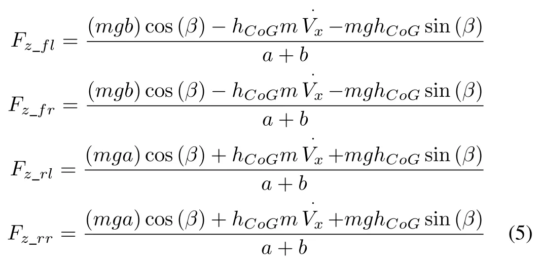
wheremis the mass of the vehicle,βpresents as the sideslip angle,gis the gravitational force,hCOGis the height of CoG.
B.Tire Model
The tire model needs to describe the dependencies of the tire force on the slip angle and ratio,friction coefficient as well as the interaction between longitudinal and lateral forces.
The slip angle for each wheel are de fined as
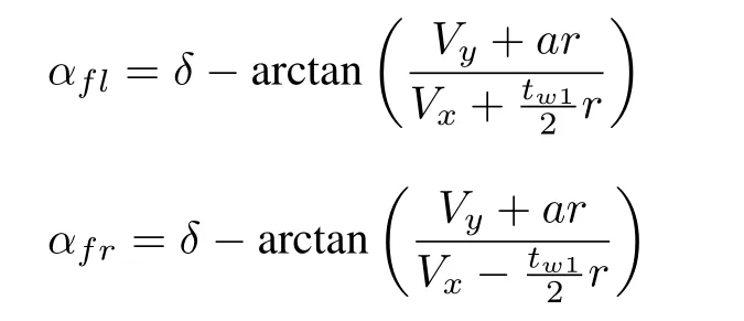
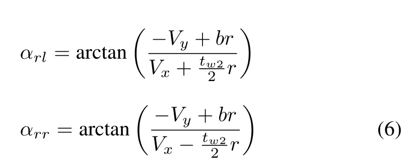
The difference between longitudinal velocity and the equivalent rotational velocity of wheel is called the longitudinal slip.The longitudinal slip ratios for each wheel for braking is given as

whereωiis the wheel angular velocity.reffis the radius of the tire.
Since the tire model for the vehicle model needs to express the interaction between longitudinal and lateral forces,the Dugoff’s tire model[36]is employed in this paper.It uses combined longitudinal and lateral forces for the vehicle dynamics simulation,and also allows the use of independent values for the tire cornering stiffness and longitudinal stiffness.
A functionλis used in Dugoff’s tire model and calculated in a separate sub-block.With all these sub-blocks together,the longitudinal and lateral tire forces can be obtained.The details of the calculation are given as below:

where
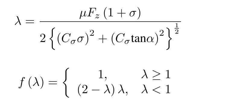
whereCσandCαare the longitudinal and cornering stiffness of the tire,respectively,λpresents as the function variable.
Note that the tire slip angle and ratio of each corresponding wheel must be used in the calculation of longitudinal and lateral forces.
Then,the relationship between the mechanical torque and the wheel rotation can be derived as

whereJwis the wheel inertia,˙ωiis the angular acceleration,Tdis the drive torque of the wheel,Tbis the brake torque of the wheel,Fxis the wheel longitudinal force andreffis the effective radius of wheel.
Wheel angular velocity or wheel rotational dynamics is related to mechanical driving and braking torque.Hence,the corrective yaw moment is only from brake torque regardless of the driveline without affecting the validation of the proposed coordination control scheme.Based on(9),it can be rewritten as
The relationship between braking torque and braking pressure is derived as

whereKbis the brake gain,Pbiis the brake pressure of the wheel.
III.MOTION MANAGEMENT SYSTEM FOR VEHICLE DYNAMICS CONTROL
This section describes the design of a coordinated control architecture for the motion management as shown in Fig.2.The architecture consists of four levels:at the top,an ADAS level that generates ideal trajectory as commands,a motion coordinator at upper-level(task manager),coordinated dynamic controllers at lower-level,and a vehicle dynamics model at the bottom.

Fig.2. Control Architecture for motion management.
The flows in the control architecture are explained as follows:Upon receiving an ideal trajectory from the ADAS command,the task manager at the upper-level is based on the coordination management laws to assign different tasks to the two independent controllers.Each of the controllers will identify their own input signal to achieve the independent control scheme at the lower-level for the controlled objects,such as the steering system actuator and the brake system actuator.Then,these two system actuators will give the active steering angle to the two front wheels,and the corrective yaw moment to the brake system for the braking torque distribution to the physics based vehicle model.After the completion of the control process,the interaction between steering system and braking system can therefore be investigated and evaluated.The details of the control architectures will be introduced in the following subsections.
A.ADAS Command Model
ADAS,as described in[9],can be considered as a co-driver.Although the scope of this paper is not to design any ADAS functionality,it is important to appropriately design ADAS command for the design and implementation of the proposed coordinated control architecture.
For any driving task ahead,it is assumed that there will be a driver command that reflects driver’s intension and a potential corresponding correction by the ADAS.To see an example,it considers the following scenario where a driver is cruising on a straight road with adaptive cruise control(ACC)function activated[37].The driver sees a vehicle ahead that is decelerating,and hence pressed the brake pedal to avoid collision.However,the ACC,as part of the ADAS,using information retrieved from sensors,may decide that an additional brake torque is needed for absolute safety.As a result,instead of sending the driver’s command to the brake controller,the ADAS will send its determined value.
In developing the ADAS command for this paper,the ADAS command is referred to as the ideal trajectory.From the perspective of the task manager and controllers,it is therefore,not necessary to distinguish between the original intension from the driver and the ideal trajectory determined by the ADAS.The only thing of concern to the control is the actual reference signal.For the sake of simplicity and demonstration of the concept of distribute control,it is assumed that the ADAS command is in use at all time,so that the vehicle will try to follow the ideal trajectory instead of driver’s intension.Hence,this resembles the situation of autonomous driving.
For the three driving scenarios described in Section IV,the ideal trajectory is build based on steering inputs as these scenarios primarily concern with turning.The steering wheel system is a control system in the vehicle that electrically amplifies the steering torque commanded by the driver.This will be input to the vehicle motion coordinator.In order to model the dynamic behavior of steering wheel system[38],the equation is simply given as

where

whereTdis the input torque on the steering wheel from the driver,Ktis a PID controller,JswandBsware the inertia and the damping constants of the steering wheel,δswandδscare the steering wheel angle and the steering column angle respectively.
Fig.3 shows the overall structure of steering wheel control scheme.The ideal trajectory provides the steering angle as an input signal to the steering wheel system that produces the desired output signal.Then,subtracting the desired output from the ADAS input signal,the error is therefore obtained.The purpose of the control system is to monitor a signal control process.It can accurately control the process by comparing the actual signal with the desired signal as to reduce the error in order to achieve a good signal-tracking performance.Note that if the controlled system is in under-steer condition,the correction angle is positive.If the controlled system is in over-steer condition,the correction angle will be negative.

Fig.3.Overall structure of ADAS command model.
For instant,Fig.4 shows variable curves of a sine wave input signal for lane changing manoeuver on a dry road with the road friction coefficient of 0.85 for Scenario I.Sinusoidal waveform is often used as the steering angle,and input to imitate the vehicle lane change in the test of vehicle dynamics.From steering angle vs.time curve,it can be seen that the steering wheel angle is subjected from zero to step peak value almost 0.35rad in a very short time and maintained for about 1s.
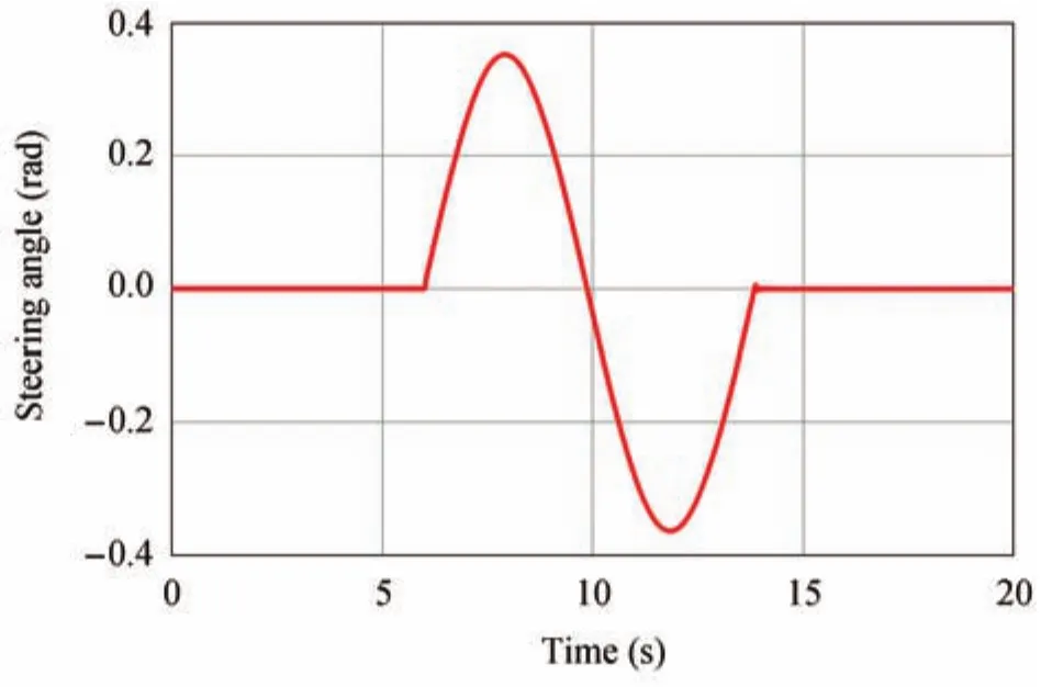
Fig.4.ADAS command for single lane changing maneuver-Scenario I.
B.Design of Motion Coordinator
In the control of vehicle dynamics,the stability of steering system and brake system are usually achieved through the control of yaw rate and side-slip angle,respectively.For this purpose,the coordination management laws are designed based on a simple kinematic model,with a small angle and constant speed assumptions[39].The motion coordinator is shown in Fig.5.

Fig.5. Upper-level-motion coordinator.
Using the coordinate transformation matrix,the velocity of point“g”is transformed in the body- fixedx-yframe to the inertial or terrainX-Yframe.Hence,the motion management laws for the model are derived as

Then,integrate the terrain-frame velocities to achieve position inX-Yas a function of body- fixed steering input,which is given as

wherexandyare the terrain coordinate frame of vehicle’sXandYvelocity.Vxis the vehicle body forward speed.δmis the angle formed between the longitudinal axis and thexaxis that can also explain as the response of corrective yaw rate.Lis the vehicle length.δis the angle from ADAS command model.βrandδrare the task signals to the coordinated controller.
As mentioned before,the stability of steering system and brake system are normally achieved through control of yaw rate and side-slip angle.The yaw moment and sideslip angle are regarded as the output of the motion coordinator.The desired yaw moment to the steering system controller is regarded as the input of the integrated steering control system.Similarly,the desired sideslip angle to the four brake system controllers are regarded as the input of the integrated braking control system.
C.Design of Dynamic Coordinated Controller
According to the control theory[40],the error of the system can be reduced by increasing the gain in the open-loop system or using higher order systems.However,the system stability and dynamic performance are also influenced by the large gain of the open-loop system or if the order of the system is too high.
Hence,the feedback closed-loop control method is utilized.The disturbance signal or transient error may deteriorate the performance at dynamic state.This,however,can be improved by a feed-forward control method.Therefore,based on the advantages of these two methods,the feedback closed-loop control strategy is combined with the feed-forward control method[41]-[43].This integrated control scheme is proposed as the dynamic coordinated motion controller.It will enhance the accuracy of steering control and the vehicle trajectory following performance.Fig.6 shows the overall structure of the integrated feed-forward and feedback control scheme.
According to Fig.6,Gfw(s)is the feed-forward transfer function,Gb(s)is the feedback transfer function,Gbr(s)is the transfer function of brake system actuator andGst(s)is the transfer function of the steering system actuator.

Fig.6. Lower-level-integrated feed-forward and feedback controllers for steering and brake system.
The control object of the coordinated control is the steering system and brake system of the vehicle.The transfer function of the steering system is obtained by yaw moment.Similarly,the transfer function of the brake system is a first-order lag system that can be obtain by the sideslip angle as the output of the motion coordinator.
The transfer function of steering system actuator is a first-order system,which can be expressed as

wheresis described as the Laplace operator,τstis the time constant of the steering system actuator,kstis constant value of the steering system actuator.
The sideslip angle is considered as input to the brake system controller.A first-order transfer function is also used for the brake system actuator which can be derived as

whereτbris the time constant of brake system actuator,kbris the constant value of the brake system actuator.
In comparison,the steering system dynamics is less complicate than the braking system dynamics due to the four brake system actuators for each tire:left front brake,left rear brake,right front brake,and right rear brake,while the steering system only has one actuator.
For the steering system controller shown in Fig.6(a),the transfer function of the PID controller is given as

wherekpandkiare the proportional and integral coefficient gain,andkdis the differential coefficient gain.
After determining theGst(s),Gbr(s),Gb(s),the transfer function of feed-forward control loopGfw(s)can be calculated and explained as below.Firstly,the input of the steering coordinated controlδris assumed to be zero.Then,the following equations can be obtained according to the Fig.6(a):

whereδΔstis the output of actuation variable of steering system actuator,βris the reference variable(sideslip angle)generated by the motion coordinator,βΔbris the output of actuation variable of brake system actuator,δris the reference variable(yaw moment)generated by the motion coordinator,δais the output variable generated by the integrated feed forward and feedback steering control system.
Based on(22)-(24),the equations(23)and(24)can be re-written as

The control target is set asE=0.Therefore,the condition should meet the target while the input of the control system is zero.
According to(25)and(26),the transfer function of the feed forward control loop can be obtained as

Similarly,for the brake system controller shown in Fig.6(b),the transfer function of PID controller is also employed that is given as

wherekpandkiare the proportional and integral coefficient gain,andkdis the differential coefficient gain.
Then,the following equations can be obtained according to Fig.6(b):

whereβais the output variable generated by integrated feed forward and feedback braking control system.
Based on(29)-(31),the equations(32)and(33)can be re-written as


TABLE IPARAMETERS OF VEHICLE MODEL

The same as the steering system controller,the following condition should be met while the input of the control system is zero as mentioned before.
According to(32)and(33),the transfer function of the feed forward control loop can be obtained as

IV.SIMULATION ANALYSIS ANDCAPABILITY EVALUATION
In this section,the modeling and simulation are carried out to evaluate the proposed coordinated control architecture,a series of computer simulations are performed with the MATLAB/Simulink environment for performance evaluation of vehicle dynamics control.Three strategies are investigated in the following simulation tests:1)coordinated control of two independent PID controllers(both steering and braking);2)control of steering system only(i.e.without brake system control);3)control of brake system only(i.e.without steering system control).These three-simulation test will be demonstrated in various driving scenarios,such as signal lane change(Scenario I),double lane change(Scenario II),and single turn(Scenario III).
A physics-based vehicle model with Dugoff’s tire model is utilized for this purpose[16].An ADAS command model is used to simulate the driver’s behavior.In the three tests,the vehicle is assumed to move with an initial velocity of 10 km/h on a dry road with the coefficient of friction 0.85.The overall structure of coordination of two independent controllers for integrated vehicle dynamics control for simulation is depicted in Fig.7.The values of vehicle parameter are listed in Table I.For instance,one of the test trajectories for Scenario I is drawn in Fig.8,and due to the limit of the page length,the figures for Scenario II and Scenario III are not shown.
Then,the interaction between steering system and brake system can be analyzed as well as the influence on the lane changing performance.More details about the analysis will be discussed in the following sub-sections.
A.Analysis of Coordinated Control and Trajectory Following Performances
Figs.10(Scenario I),14(Scenario II)and 17(Scenario III)show the three yaw rate responses generated by simulation of three tests against to the task signal-yaw rate(reference signal).As it can be seen from the results,the uncontrolled steering system of vehicle,the amplitude of the desired yaw rate becomes larger against the reference signal.On the other hand,in the case of coordinated control,the desired yaw rate response tracks well to the task signal-yaw rate.Also,a slight in fl uence on the signal-tracking is observed when the brake system is uncontrolled,but the output of yaw rate is nearly converging to the reference signal.Similar phenomenon is also con firmed by Fig.9,the amplitude becomes larger when control braking only.On the other hand,a small error is produced when control steering only.
Similarly,the comparisons of sideslip angle tracking behavior are drawn in Figs.11(Scenario I),15(Scenario II)and 18(Scenario III).The vehicle with coordination of steering and braking for integrated vehicle dynamics control achieves a good signal-tracking performance in comparison to the task signal-sideslip angle(reference signal).The amplitude of desired output signal still becomes larger when the steering system is uncontrolled,and will slightly influence the signal tracking when control braking only.In comparison,the proposed coordinated control system can improve the vehicle signal-tracking performance.
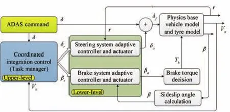
Fig.7. Detailed control scheme with control and feedback signals.
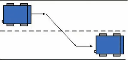
Fig.8. Test trajectory-Scenario I.

Fig.9. Yaw rate versus steering angle-controlled and uncontrolled-Scenario I.
In order to investigate the capability of trajectory following,the trajectory-tracking performances are demonstrated for three different scenarios which are drawn in Figs.12(Scenario I),16(Scenario II)and 19(Scenario III).The same conditions are applied,and the desired trajectories generated by the three simulation tests are compared to the ideal trajectory which is provided by ADAS.It clearly shows that the coordinated control of the steering system and the brake system(test 1:coordinated control of two independent PID controllers)can track the ideal trajectory well and reaches a better trajectory-tracking performance than the other two tests(test 2:control of steering system only,and test 3:control of brake system only).To sum up,the control of steering system without brake system control has a small undershoot,whilst the control of brake system without steering system control has a significant overshoot.
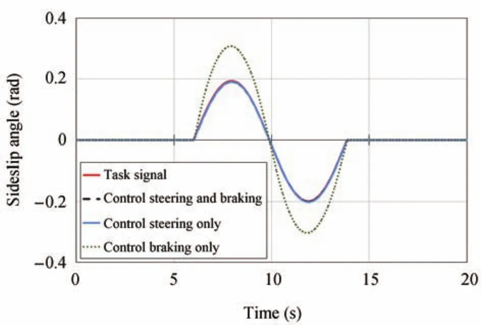
Fig.11.Responses of sideslip angle versus task signal-Scenario I.

Fig.12.Trajectory following comparison-Scenario I.
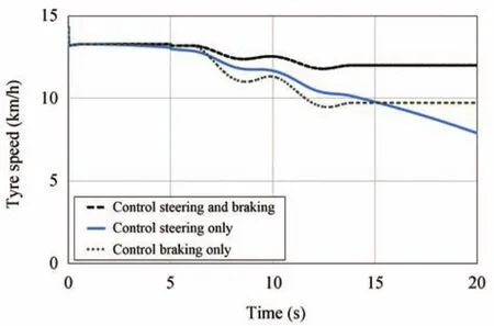
Fig.13.Comparison of tire rotational speeds-Scenario I.
Moreover,the behavior comparison of the tire rotational speeds is shown in Fig.13.Again,the proposed coordination motion control scheme can maintain the tire rotational speed at constant speed.On the other hand,the tire rotational speed is kept reducing when the brake system is uncontrolled(test 3).

Fig.14. Responses of yaw rate versus task signal-Scenario II.
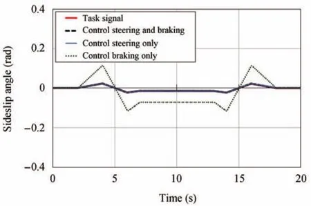
Fig.15. Responses of sideslip angle versus task signal-Scenario II.

Fig.16. Trajectory following comparison-Scenario II.
B.Discussion
The concept of a motion management system and its coordinated control architecture is designed and demonstrated in this paper.The concept is verified through a set of simulations over different input trajectories and control strategies.Given an ideal trajectory in terms of steering angle,the upper-level motion coordinator successfully manages the task into a yaw moment and sideslip angle and distribute them respectively to the steering controller and brake controller at the lower-level controllers.The vehicle performance simulated through a 3-DoF vehicle model was analyzed in the previous section.
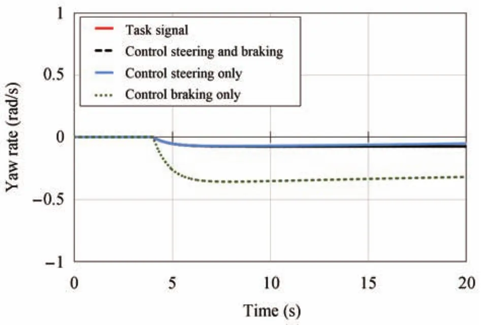
Fig.17.Responses of yaw rate versus task signal-Scenario III.
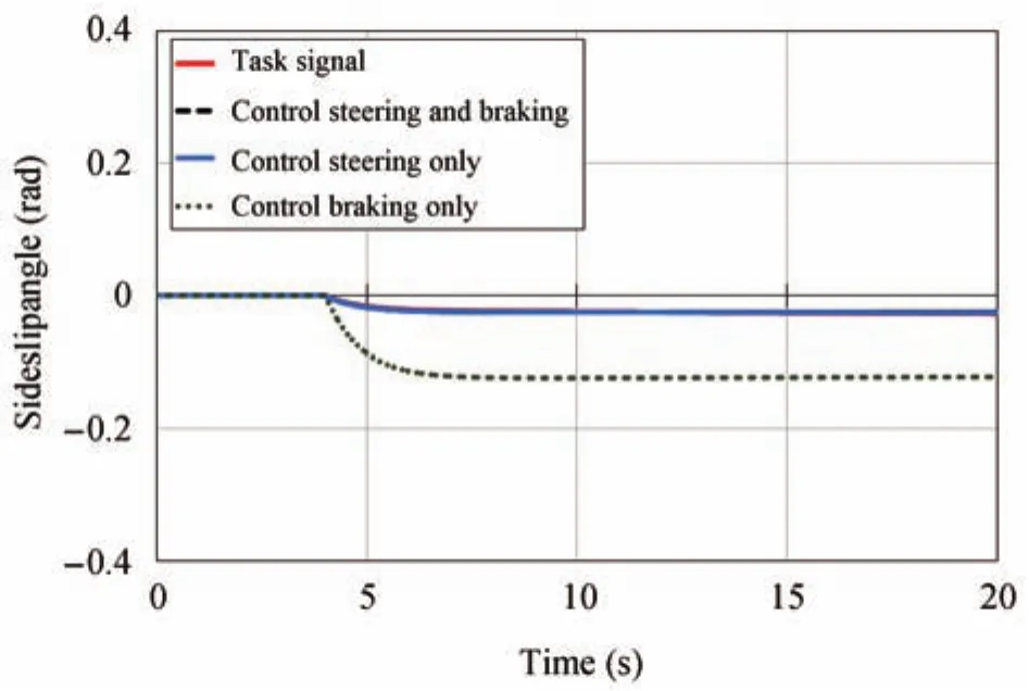
Fig.18.Responses of sideslip angle versus task signal-Scenario III.
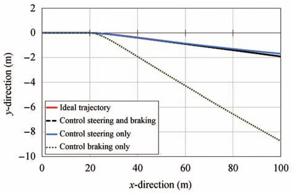
Fig.19.Trajectory following comparison-Scenario III.
The advantage of the coordinated control over traditional control schemes,e.g.,series or independent control,is that it allows interactions among systems to be investigated while the design of the individual system can still be done independently.However,the complexity and difficultly in designing such a motion management system may grow quickly with increasing number of systems.This is because that one needs to design and derive a set of motion management laws in the upper-level motion coordinator as in Fig.2 to divide the ADAS commands and distribute them to individual components under the control architecture.
One of the key features of the proposed control architecture for the elementary motion management system is being not susceptible to details of model changes.Starting with a simplified vehicle dynamics model that only considers longitudinal,lateral and yaw motion,the concept of coordinated control was demonstrated in this paper.At an industrial level where the requirement to model fidelity is high,the coordinated control scheme must be able to adapt to model changes.To validate that the designed control architecture indeed is non-susceptible to model changes,the simplified vehicle dynamics model is extended to a higher fidelity model that also considers roll motion of the vehicle.Detailed mathematical descriptions of the model and simulation results are provided in Appendix I.As observed in the simulation results depicted in Fig.20,the performance of the 8-DoF vehicle model in following the single lane change trajectory(Scenario I)is reasonably acceptable,but less accurate in comparison to that of the 3-DoF vehicle model.This discrepancy between the simulation results is believed to be caused by the addition of roll-motion in the vehicle model.
V.CONCLUSIONS AND FUTURE WORK
In this paper,a coordinated control architecture for vehicle motion control has been developed.The architecture is analyzed with integrated open source physics models of the vehicle dynamics and ADAS command models.Specifically,the steering and braking models were implemented in MATLAB/Simulink and integrated into a physics based vehicle model with three degrees of freedom to include a broadly accepted tire model.The simulation models and the coordinated control architecture are made available for open access[33].
The vehicle dynamic responses in the lane changing maneuver simulation tests indicated that the control of steering system without brake system control has a slight undershoot of an intended trajectory from an ADAS system;and the control of brake system without steering system control has a signi ficant overshoot.On the other hand,the“coordinated control”strategy successfully damped out the deviation errors,and gave much greater precision in following the intended trajectory.
The system of systems(SoS)control architecture and strategy developed are “coordinated control”(as opposed to a monolithic integration strategy).This,in principle,permits the constituent systems of the SoS to be developed and operated independently,which is an important consideration for an automotive OEM.The design intent of the motion management system is that it should allow adding new system models,e.g.,suspension system,and their corresponding controllers in a distributive manner within the motion management system.As such,by extending the scope of the motion management system,the system should provide a means to investigate various distributed control strategies such as differential braking.Moreover,how new systems and their corresponding control strategy will interfere with existing systems,e.g.steering system,in terms of control performance and stability will be topics for future research.
APPENDIX
To demonstrate the claim that the proposed coordinated control architecture is not susceptible to details of model changes,the three degree of freedom(3-DoF)vehicle dynamics model is extended to the eight degrees of freedom(8-DoF)with associated changes in the tire model in this Appendix.Simulation results are also shown and compared with the one presented in the main body of the paper.
A.Vehicle Model
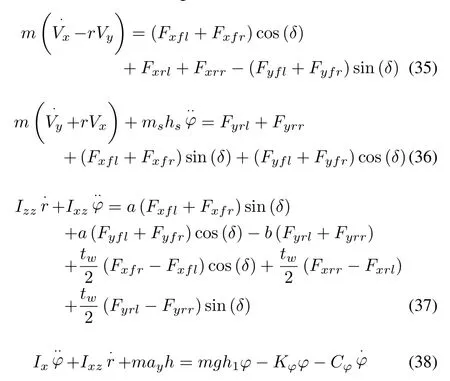
In addition to the longitudinal,lateral and yaw rate,the dynamics of an 8-DoF vehicle also concerns roll motion.The consideration of roll motion revises the set of equations of motions into the following[12]:
According to the longitudinal and lateral load transfers,the instantaneous vertical tire load acting on each wheelFziduring dynamic maneuvers is the sum of the static tire load plus load transfer that is due to longitudinal acceleration,lateral acceleration,and body roll motion respectively[12].This effect can be described as

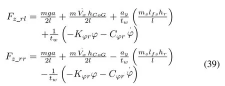
wheremsis the sprung mass of the vehicle,gis gravity acceleration,hfandhrare the height of front and rear roll centre,lfsandlrsare the distance from sprung mass CoG to front and rear axle,respectively.
B.Tire Model
Similar to 3-DF vehicle,the tire model[32]is utilized in this report.Then,the slip angles for each wheel are de fined as

The speeds at the centre of each wheel are de fined as
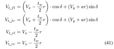
Longitudinal slip ratios during braking remains unchanged as described by(7).The tire model in the full vehicle model needs to express the interaction between longitudinal and lateral tire forces that can be derived as follows:

whereλis given by

whereCσandCαare the longitudinal and cornering stiffness of the tire,respectively.λpresents as the function variable.
Finally,(9)-(11)remains unchanged in this model to describe the relationship between the mechanical torque and the wheel rotation,the relationship between wheel angular velocity and mechanical driving and braking toque,and the relationship between braking torque and braking pressure,respectively.
C.Performance Analysis of Simulation Result
In order to validate the susceptibility of the coordinated control architecture with changing model fidelity,the 8-DoF vehicle is implemented in Simulink/MATLAB and used to substitute the 3-DoF vehicle dynamics block in the built models provided in[33].For the single lane change test,with the same input trajectory,a simulation test is performed.The result from the 8-DoF(green dash)is depicted in Fig.20 with comparison to the ideal trajectory(red)and the previous simulation result with 3-DoF vehicle model(black dot).As observed,the 3-DoF vehicle model shows a good trajectory following performance.However,the 8-DoF vehicle model attempt at following the ideal trajectory,is less accurate at this point with as light deviation due to the effect of roll motion.
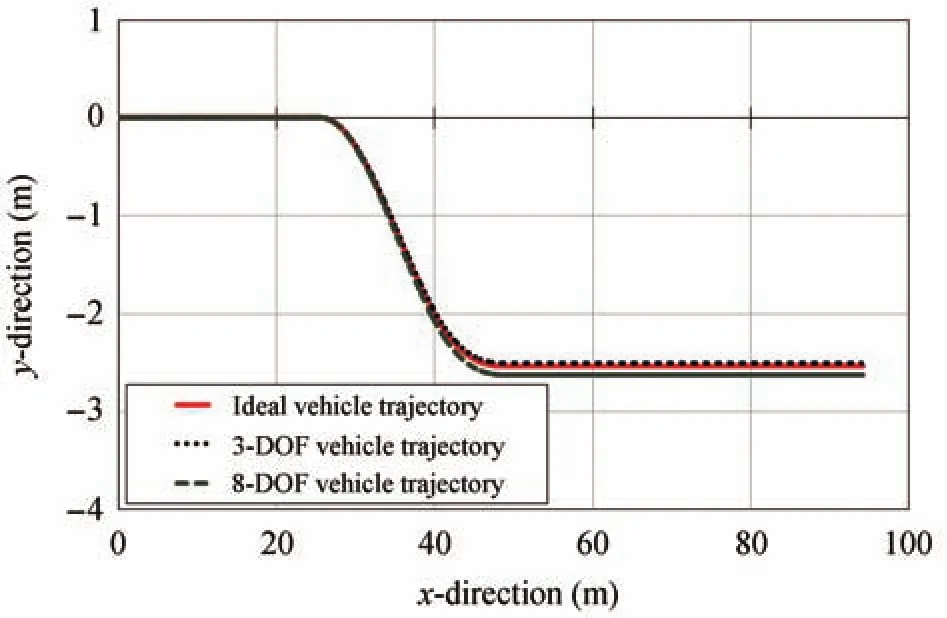
Fig.20.Performance comparison of trajectory following by different vehicle model,3-DoF and 8-DoF.
[1]J.Q.Wang,L.Zhang,D.Z.Zhang,and K.Q.Li,“An adaptive longitudinal driving assistance system based on driver characteristics,”IEEE Trans.Intell.Transp.Syst.,vol.14,no.1,pp.1-12,Mar.2013.
[2]H.Kim,D.Kim,I.Shu,and K.Yi,“Time-varying parameter adaptive vehicle speed control,”IEEE Trans.Veh.Technol.,vol.65,no.2,pp.581-588,Feb.2015.
[3]A.K.G.Balagh,F.Naderkhani,and V.Makis,“Highway accident modeling and forecasting in winter,”Transp.Res.A Policy Pract.,vol.59,pp.384-396,Jan.2014.
[4]C.Z.Guo,J.Meguro,Y.Kojima,and T.Naito,“A multimodal ADAS system for unmarked urban scenarios based on road context understanding,”IEEE Trans.Intell.Transp.Syst.,vol.16,no.4,pp.1690-1704,Aug.2015.
[5]Advanced driver assistance systems. [Online]. Available:http://en.wikipedia.org/wiki/Advanced driver assistance systems
[6]V.A.Butakov and P.Ioannou,“Personalized driver/vehicle lane change models for ADAS,”IEEE Trans.Veh.Technol.,vol.64,no.10,pp.4422-4431,Oct.2015.
[7]D.O.Cualain,M.Glavin,and E.Jones,“Multiple-camera lane departure warning system for the automotive environment,”IET Intell.Transp.Syst.,vol.6,no.3,pp.223-234,Sep.2012.
[8]P.Angkititrakul,R.Terashima,and T.Wakita,“On the use of stochastic driver behavior model in lane departure warning,”IEEE Trans.Intell.Transp.Syst.,vol.12,no.1,pp.174-183,Mar.2011.
[9]M.R.Spena,F.Timpone,and F.Farroni,“Virtual testing of advanced driving assistance systems,”Int.J.Mechan.,vol.9,pp.300-308,Dec.2015.
[10]C.Visvikis,T.L.Smith,M.Pitcher,and R.Smith,“Study on lane departure waring and lane change assistance systems,”Transport Research Laboratory,Project Report PPR 374,Nov.2008.
[11]M.Doumiati,O.Sename,L.Dugard,J.J.Martinez-Molina,P.Gaspar,and Z.Szabo,“Integrated vehicle dynamics control via coordination of active front steering and rear braking,”Eur.J.Control,vol.19,no.2,pp.121-143,Mar.2013.
[12]X.J.Yang,Z.C.Wang,and W.L.Peng,“Coordinated control of AFS and DYC for vehicle handling and stability based on optimal guaranteed cost theory,”Veh.Syst.Dyn.,vol.47,no.1,pp.57-79,Jan.2009.
[13]J.X.Wang,R.R.Wang,H.Jing,M.Chadli,and N.Chen,“Coordinated active steering and four-wheel independently driving/braking control with control allocation,”in Proc.2015American Control Conference,Chicago,IL,USA,2015,pp.5420-5425.
[14]J.H.Guo,P.Hu,and R.B.Wang,“Nonlinear coordinated steering and braking control of vision-based autonomous vehicles in emergency obstacle avoidance,”IEEE Trans.Intell.Transp.Syst.,vol.17,no.11,pp.3230-3240,Nov.2016.
[15]R.Marino,S.Scalzi,and M.Netto,“Nested PID steering control for lane keeping in autonomous vehicles,”Control Eng.Pract.,vol.19,no.12,pp.1459-1467,Sep.2011.
[16]S.Di Cairano,H.E.Tseng,D.Bernardini,and A.Bemporad,“Vehicle yaw stability control by coordinated active front steering and differential braking in the tire sideslip angles domain,”IEEE Trans.Control Syst.Technol.,vol.21,no.4,pp.1236-1248,Jul.2013.
[17]S.Yim,J.Choi,and K.Yi,“Coordinated control of Hybrid 4WD vehicles for enhanced maneuverability and lateral stability,”IEEE Trans.Veh.Technol.,vol.61,no.4,pp.1946-1950,May 2012.
[18]B.Y.Li,H.P.Du,and W.H.Li,“Trajectory control for autonomous electric vehicles with in-wheel motors based on a dynamics model approach,”IET Intell.Transp.Syst.,vol.10,no.5,pp.318-330,Jun.2016.
[19]N.Ando and H.Fujimoto,“Yaw-rate control for electric vehicle with active front/rear steering and driving/braking force distribution of rear wheels,”inProc.11th IEEE Int.Workshop on Advanced Motion Control,Nagaoka,Niigata,Japan,2010,pp.726-731.
[20]J.Tjonnas and T.A.Johansen,“Stabilization of automotive vehicles using active steering and adaptive brake control allocation,”IEEE Trans.Contr.Syst.Technol.,vol.18,no.3,pp.545-558,May 2010.
[21]B.A.Guvenc,T.Acarman,and L.Guvenc,“Coordination of steering and individual wheel braking actuated vehicle yaw stability control,”inProc.2003 IEEE Intelligent Vehicles Symp.,Columbus,OH,USA,2003,pp.288-293.
[22]L.Zhai,T.M.Sun,and J.Wang,“Electronic stability control based on motor driving and braking torque distribution for a four in-wheel motor drive electric vehicle,”IEEE Trans.Veh.Technol.,vol.65,no.6,pp.4726-4739,Jun.2016.
[23]Z.B.Shuai,H.Zhang,J.M.Wang,J.Q.Li,and M.G.Ouyang,“Combined AFS and DYC control of four-wheel-independent-drive electric vehicles over CAN network with time-varying delays,”IEEE Trans.Veh.Technol.,vol.63,no.2,pp.591-602,Feb.2014.
[24]J.M.Wang and R.G.Longoria,“Coordinated and reconfigurable vehicle dynamics control,”IEEE Trans.Control Syst.Technol.,vol.17,no.3,pp.723-732,May 2009.
[25]M.Abe,Y.Kano,K.Suzuki,Y.Shibahata,and Y.Furukawa,“Side-slip control to stabilize vehicle lateral motion by direct yaw moment,”JSAE Rev.,vol.22,no.4,pp.413-419,Oct.2001.
[26]J.M.Wang and R.G.Longoria,“Coordinated vehicle dynamics control with control distribution,”inProc.American Control Conf.,Minneapolis,MN,USA,2006,pp.5348-5353.
[27]W.He,Y.T.Dong,and C.Y.Sun,“Adaptive neural impedance control of a robotic manipulator with input saturation,”IEEE Trans.Syst.Man Cybern.Syst.,vol.46,no.3,pp.334-344,Mar.2016.
[28]W.He,Z.C.Yan,C.Y.Sun,and Y.A.Chen,“Adaptive neural network control of a flapping wing micro aerial vehicle with disturbance observer,”IEEE Trans.Cybern.,vol.47,no.10,pp.3452-3465,Oct.2017.
[29]W.He and S.Zhang,“Control design for nonlinear fl exible wings of a robotic aircraft,”IEEE Trans.Control Syst.Technol.,vol.25,no.1,pp.351-357,Jan.2017.
[30]J.J.He,D.A.Crolla,M.C.Levesley,and W.J.Manning,“Coordination of active steering,driveline,and braking for integrated vehicle dynamics control,”Proc.Inst.Mech.Eng.Part D J.Automob.Eng.,vol.220,no.10,pp.1401-1421,Oct.2006.
[31]C.Hatipoglu,U.O¨zgu¨ner,and K.A.Redmill,“Automated lane change controller design,”IEEE Trans.Intell.Transp.Syst.,vol.4,no.1,pp.13-22,Mar.2003.
[32]J.E.Naranjo,C.Gonza´lez,R.Garc´ıa,and T.de Pedro,“Lane-change
fuzzy control in autonomous vehicles for the overtaking maneuver,”IEEE Trans.Intell.Transp.Syst.,vol.9,no.3,pp.438-450,Sep.2008.
[33]T.C.Lin,S.Ji,C.E.Dickerson,and D.Battersby,“Coordinated control system for ADAS:Simulink Models,” figshare,2017,doi:10.17028/rd.lboro.431.
[34]J.H.Guo,K.Q.Li,and Y.G.Luo,“Coordinated control of autonomous four wheel drive electric vehicles for platooning and trajectory tracking using a hierarchical architecture,”J.Dyn.Syst.Meas.Control,vol.137,no.10,pp.1-18,Oct.2015.
[35]G.D.Yin,N.Chen,and P.Li,“Improving handling stability performance of four-wheel steering vehicle viaµ-synthesis robust control,”IEEE Trans.Veh.Technol.,vol.56,no.5,pp.2432-2439,Sep.2007.
[36]H.Dugoff,P.S.Fancher,and L.Segel,“Tire performance characteristics affecting vehicle response to steering and braking control inputs,”Final Report,Of fice of Vehicle Systems Research,US National Bureau of Standards,Washington,DC,USA,Contract CST-460,1969.
[37]M.G.Plessen,D.Bernardini,H.Esen,and A.Bemporad,“Spatialbased predictive control and geometric corridor planning for adaptive cruise control coupled with obstacle avoidance,”IEEE Trans.Control Syst.Technol.,vol.26,no.1,pp.38-50,Jan.2018.
[38]G.B.Shi,S.H.Zhao,and J.Min,“Simulation analysis for electric power steering control system based on permanent magnetism synchronization motor,”inProc.2nd Int.Conf.Electronic&Mechanical Engineering and Information Technology,Paris,France,2012.
[39]M.Naraghi,A.Roshanbin,and A.Tavasoli,“Vehiclestability enhancement-an adaptive optimal approach to the distribution of tyre forces,”Proc.Inst.Mech.Eng.Part D J.Autom.Eng.,vol.224,no.4,pp.443-453,Apr.2010
[40]S.S.Hu,Automatic Control Theory.4th ed.Beijing,China:Beijing Science Press,2001.
[41]N.R.Kapania and J.C.Gerdes,“Design of a feedback-feed forward steering controller for accurate path tracking and stability at the limits of handling,”Veh.Syst.Dyn.,vol.53,no.12,pp.1687-1704,Jun.2015.
[42]G.Otten,T.J.A.de Vries,J.van Amerongen,A.M.Rankers,and E.W.Gaal,“Linear motor motion control using a learning feed forward controller,”IEEE/ASME Trans.Mechatron.,vol.2,no.3,pp.179-187,Sep.1997.
[43]E.Kayacan,H.Ramon,and W.Saeys,“Robust trajectory tracking
error model-based predictive control for unmanned ground vehicles,”IEEE/ASME Trans.Mechatron.,vol.21,no.2,pp.806-814,Apr.2016.
杂志排行
IEEE/CAA Journal of Automatica Sinica的其它文章
- Decomposition Methods for Manufacturing System Scheduling:A Survey
- Nonlinear Bayesian Estimation:From Kalman Filtering to a Broader Horizon
- Vehicle Dynamic State Estimation:State of the Art Schemes and Perspectives
- An Online Fault Detection Model and Strategies Based on SVM-Grid in Clouds
- An Adaptive RBF Neural Network Control Method for a Class of Nonlinear Systems
- Stabilization of Uncertain Systems With Markovian Modes of Time Delay and Quantization Density
