Design and experiment of vertical circular separating and conveying device for potato combine harvester
2018-03-01YangRanbingYangHongguangShangShuqiNiZhiweiLiuZhishenGuoDong
Yang Ranbing, Yang Hongguang, Shang Shuqi※, Ni Zhiwei,Liu Zhishen, Guo Dong
(1. College of Mechanical and Electrical Engineering, Qingdao Agricultural University, Qingdao 266109, China;2. Shandong Provincial Engineering Technology Research Center for Root Crops Production Equipment, Qingdao 266109, China)
0 Introduction
In recent years, with the increasing use of potato as a staple food, the potato planting area has increased gradually in China. In 2015, its total planting area were 5.53×10⁷hm2,accounting for about 4.87% of total planting area of food crops[1]. Meanwhile, higher quality requirements for mechanized harvesting have also been put forward. At present, the small segmented potato harvester is widely used in China[2-5]. However, the process of manual picking up potato with the traditional small segmented potato harvester is time-consuming, tedious, and inefficient, and these harvesters have not been able to keep pace with the current rapid development of the potato industry. Research and development of the technology and equipment for combine harvesting are particularly important.
At the beginning of the 20th century, international researchers and institutions began attempts to mechanize potato harvesting, especially in some developed countries,where technology is at a higher level than in developing countries. With the development of the large-scale harvesting machine, which can complete the haulm-killing,digging, separating and conveying operations,standardization and serialization have been realized[6-7].Some researchers in developed countries such as Germany,the United States and Belgium devised the GT-170S,Double-L973 reflux and Spirit-6200 double-row self-propelled potato combine harvesters.
In China, less work has been done on the development of the potato combine harvester, and the technology is not mature. Due to differences in planting patterns and climate conditions, and the introduction of foreign machinery has not occurred in China. Some researchers and institutions have been developing the technology and equipment for combine harvesting, but due to the objective conditions of the restrictions, the relevant harvester has not been widely utilized in China. MENOBLE developed the 1710-type potato combine harvester. Wei Hongan et al[8]developed the 4UFD-1400-type potato combine harvester, which enables the one-stop completion of digging, soil separation, stem removal, conveying, grading, collecting and bagging procedures.
At present, most of the separating and conveying devices of the potato combine harvester are rod-link chains and rod-link belts. The use of these devices makes the entire structure unstable. The operation is not flexible enough, and the separation is poor, restricting the development of this technology for potato combine harvesting[2,9]. Therefore,research on a vertical circular separating and conveying device is significant and can provide a basis for the development and design of new types of potato combine harvesters. Moreover, it can help promote the development of mechanized potato production, especially in China.
1 Structure and working principle of the vertical circular separating and conveying device
1.1 Structure
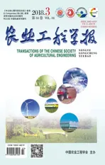
The structure of the vertical circular separating and conveying device is determined by it’s function of the delivery and separation of the potato in vertical space[7,10].As shown in Fig.1, the vertical circular separating and conveying device consists primarily of a frame, a belt-type conveying mechanism, a transverse transfer mechanism, a vertical circular separating screen, and a secondary cleaning and conveying mechanism. The vertical circular separating screen is positioned between the fixed wheel groups on the frame, the belt-type conveying mechanism is positioned near the lower part of the vertical circular separating screen, and the transverse transfer mechanism and the secondary cleaning and conveying mechanism are arranged in the circular orbit of the vertical circular separating screen.
1.2 Working principle
When the harvester operates, the digging shovel digs out the potato. The potato advances into the chain-link-type ascending mechanism and moves up to the top. Then, with the belt-type conveying mechanism moving backward during transport by the transverse transfer mechanism,rubber fingers dip the contents of the lifting hopper onto the vertical circular separating screen. Under the meshing transmission of the gear and the annular gear, the vertical circular separating screen can improve the circular lifting of the potato, soil and impurities. In the process of circular lifting, the separation of potato and soil occurs by relative movement. A protective screen is welded onto the frame formed by steel bars that are welded along the arc of the two circular orbits. The protective screen and lifting hopper form a relatively closed space to prevent the potato from falling off during the rotation-separation process. The lifting hopper moves the potato to the secondary cleaning and conveying mechanism, through which they pass by gravity, after which the potato move through the rod conveyor chain and into the collection box.
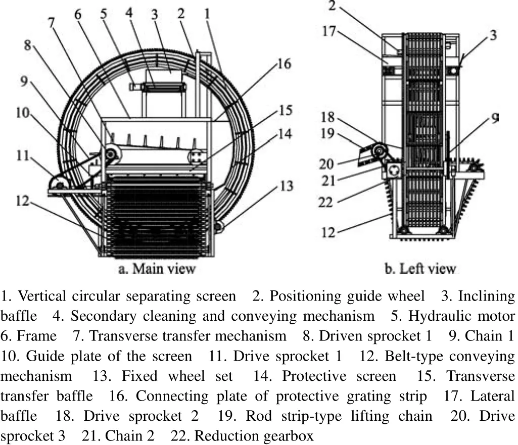
Fig. 1 Structure of separating and conveying device
2 Design of key components of the vertical circular separating and conveying device
2.1 Design of the vertical circular separating screen
The vertical circular separating screen is one of the key components of the vertical circular separating and conveying device. Its primary function is to carry out the transport and separation of potato, soil and impurities in the vertical space.As shown in Fig.2, the vertical circular separating screen consists of an annular gear, an elastic rope, an external circular orbit, an inner circular orbit and a spacing grid. The annular gear is engaged with the driving gear on the output shaft of the gear box to drive the vertical circular separating screen to rotate in the vertical space. The fixed wheel set on the frame consists of a driving gear, guide wheels and a horizontal positioning guide wheel, which positions and guides the vertical circular separating screen. There are eight guide wheels, and the two sides of the fixed wheel set are positioned at the two sides of the lower part of the vertical circular separating screen. There are two positioning guide wheels, which are positioned on the upper side of the vertical circular separating screen and are in contact with the sides of the circular orbit. The spacing grid is welded between the two circular orbits[11-14]. The elastic rope passes through the barrier along the edge of the line array pore, and with the spacing grid, this constitutes the circular arrangement of the lifting hopper.
The required structure size, stability and harvest width led to the following parameters for the design of vertical circular separating screen: the external circular orbit radius is 850 mm, the inner circular-orbit radius is 725 mm, the width is 350 mm, and the screen is divided into 18 lifting hoppers. Between the two external circular orbits are 11 uniform elastic ropes, which have a great influence on the separation ability of the elastic-rope gap. Based on the physical size of the potato and the deformation of the elastic rope, the necessary elastic rope gap was calculated to be 24 mm.
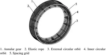
Fig. 2 Structure of vertical circular separating screen
2.2 Design of the transverse transfer mechanism
The transverse transfer mechanism is another key component of the vertical circular separating and conveying device. It employs a rod-type conveying chain to transport potato to the vertical circular separating screen and lifting hopper. Its structure and parameters directly affect the transfer and damage rates[15]. As shown in Fig.3, the transverse transfer mechanism is composed of rubber fingers,a transfer belt, two drive rubber rollers, a protective collar and a connecting plate. The transverse transfer mechanism is positioned on the frame through a connecting plate and bearing chock. The rubber fingers are mounted on a horizontal conveyor belt that is driven by the drive rubber roller.

Fig. 3 Structure of transverse transfer mechanism
In order to carry out the transverse transfer function,combined with the vertical circular separating screen, the width of the transfer belt is 180 mm, and the radii of the two drive rubber rollers are 168 and 112 mm. The eleven groups of rubber fingers are uniformly distributed on the transfer belt. Each group consists of 4 rubber fingers. The spacing between groups of rubber fingers is 115 mm, and the spacing between rubber fingers within a group is 15.5 mm. The use of rubber fingers can reduce the damage incurred by the potato during transverse transfer[16].
Based on the analysis of the transverse mechanical properties and kinematic characteristics of the delivery process, the appropriate rubber-finger draft angle for successful potato pulling and reduced damage rate is 3 degrees.In addition, the movement parameters of the transverse transfer mechanism mainly involve the linear speed of the transfer belt, which is determined by the transfer-belt linear speed (vp) and the moving forward speed (vm); λ=vp/vmand is usually within the range of 0.8 to 2.5[8,17]. If the transferbelt linear speed is too great, the potato can easily slide during transfer, resulting in damage. To reduce the damage rate, the value of λ should be greater than 1; that is, the transfer-belt linear speed should be higher than the moving forward speed. Meanwhile, to achieve higher productivity while ensuring a good-quality harvest, the moving forward speed should be suitable for semi- viscous soil and sandy soil. A speed from 0.8 to 1.4 m/s is appropriate[18-19].Substituting λ=1.5 into the equation, we obtain a transfer-belt linear speed in the range of 1.2 to 2.1 m/s.
3 Analysis of kinematic and dynamic characteristics
3.1 Analysis of the force and motion of a potato in the transverse transfer
The transverse motion of the potato occurs primarily with the belt-type conveying mechanism and transverse transfer mechanism. As shown in Fig.4a, the movement speed of the potato in the belt-type conveying mechanism can be decomposed into the relative speed (Ve) of the belt-type conveying mechanism and the transverse speed (Vr)of the transverse transfer mechanism. The composite of these velocities is the absolute speed (Va).

Fig. 4 Schematic diagram of force and motion of potato in transverse transfer
The complex motion of the potato is simplified to the motion of a particle, ignoring the interaction forces and the air resistance[20-21]. As shown in Fig.4b, the potato is mainly influenced by its own gravity (mg), the pulling force (F), and the supporting force (FN) and friction force (Ff) of the belt-type conveying mechanism. For transverse transfer of the potato, the condition F >Ffmust be met. At the same time, the falling movement of the potato from the belt-type conveying mechanism into the vertical circular separation screen can be regarded as horizontal projectile motion with a certain initial speed. The coordinate system was established with the potato center of mass as the origin O. The equations of the motion parameters of the potato are as follows:

where x is horizontal displacement in meters of the potato from O while being thrown into the lifting hopper; y is vertical displacement in meters of the falling potato from point O; vais initial speed of the horizontal motion, m/s; t is time for the potato to fall from point O to the lifting hopper,s; g is acceleration gravity, 9.8 m/s2.
3.2 Analysis of the force and motion of the potato during circular lifting
When the potato in the transverse transfer mechanism fall into the elastic rope as the hopper moves, the gravitational potential energy, kinetic energy and elastic potential energy of the elastic rope undergo a certain range of repeated transformation, thus greatly reducing injury to the potato. At the same time, in the process of the transformation of the potential energy and elastic potential energy, the elastic rope can remove soil from the potato surface.
In the process of being lifted, the potato moves with the lifting hopper, and the lifting height and lifting position change due to the rotation of the circular separating screen.The effect of the combined action of the support force and the gravitational force results in movement and rolling of the potato[22-23]. The potato and soil can be separated well, due to the combined actions of circular motion, sliding and self-rolling, and the potato in the lifting hopper is approximated as a particle.
As shown in Fig.5, with the belt-type conveying mechanism of the potato in the transverse transfer mechanism, the pulling force into the lifting hopper, and the elastic bounce over a certain distance, the movement trajectory is O→A→B→C→D→E→F→G. As shown in Fig.6, the four points C, D, E, F are the important positions for analysis.
Fig. 5 Schematic diagram of potato motion trajectories
As shown in Fig.6a, as the potato falls into the lifting hopper, the first contact with the elastic rope occurs at point A, and the potato is then rebounded to point B. During this process, the potential energy of gravity is transformed, and the potato moves down to point C. After the potato reaches point C, mainly due to its own gravity, support force FN11is provided by the elastic rope and support force FN12is provided by the spacing grid.
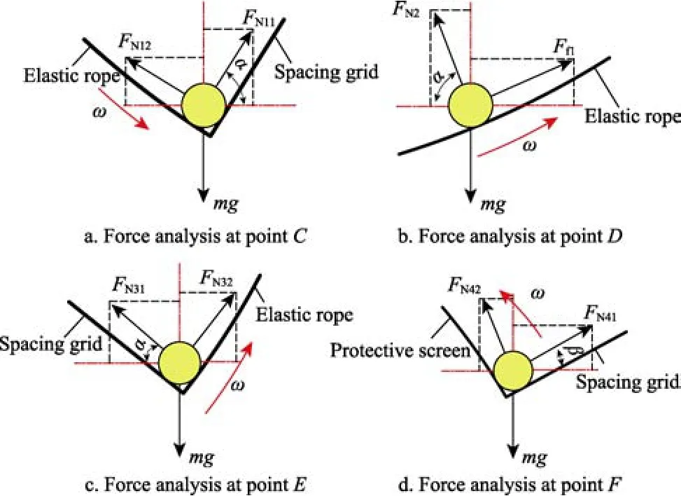
Fig. 6 Potato force analysis in different locations
At this stage, the lifting hopper moves the potato in a circular motion, and the force-balance equations are as follows:

Where R is the distance from the rotation center of the separating screen to the center of mass of the potato, mm.
As shown in Fig.6b, when the lifting hopper rotates counterclockwise to its lowest point, the support force of the spacing grid on the potato is zero. At this time, the potato is mainly influenced by its own gravity, the support force (FN2)of the elastic rope and the friction force (Ff1) generated during the movement. The potato is not balanced: while the side with the lifting hopper moves in a circular motion, the side in contact with the roller slides to point E. The force-balance equation of the potato at point D along the CE segment is as follows

As shown in Fig.6c, as the lifting hopper continues to rotate, the potato moves to point E, in a circular motion with the lifting hopper. The potato is mainly influenced by its own gravity, the support force FN31provided by the elastic rope and the support force FN32provided by the spacing grid.As the spacing-grid support force increases gradually, the elastic-rope support force decreases. At this time, the force-balance equations are as follows

As shown in Fig.6d, when the lifting-hopper spacing grid moves close to the horizontal position, the potato moves from point E to point F. At this time, the potato is mainly influenced by its own gravity, the support force FN42of the spacing grid and the support force FN41of the protective screen. At this stage, with the protective screen carrying out a circular motion, the force-balance equations are as follows

When the lifting hopper is moved to the end of the protective screen, the potato falls to the secondary cleaning and conveying mechanism due to its own gravity. At the highest point of its motion, the following equation should be satisfied

From the above analysis of the kinematic and mechanical characteristics of the potato, the transverse transfer and circular lifting during ascension are more complex. The linear speed of the transverse transfer belt and the rotational speed of the circular orbit have important effects on harvest performance.
4 Experimental analysis
4.1 Experimental conditions
The vertical circular separating and conveying device was installed on the self-propelled potato combine harvester developed by Zhengxing Machinery Co., Ltd., Henan Province, China. As shown in Fig.7a, the potato harvester consists of a depth-limiting device, a digging device,rod-link ascending chains, a crawler track walking device,road wheels, a hydraulic oil tank, a potato collection box and a vertical circular separating and conveying device. The prototype used for the experiment is shown in Fig.7b. The potato harvester uses a rice and wheat combine harvester crawler chassis. The engine has a maximum power of 40 kW,the harvest width is 1 550 mm, and the pure work-hour productivity ranges from 0.35 to 0.55 hm2/h.
Field harvest test was conducted in the experimental field in Fuji Township, Kaifeng City, Henan Province,China in July 2016. The potato variety studied is named Helan 15, which is the main variety cultivated in Henan Province. The area of the experimental field was 120 m×100 m, the planting pattern was ridge cultivation, the soil texture was clay loam, the row spacing of the plants was 780 mm, the ridge height was 260 mm, the planting density was 230 mm, the moisture content of the soil was 10.28%,and the soil hardness was 413 kPa.

Fig. 7 Whole machine structure and prototype of potato combine harvester
4.2 Experimental factors and index
According to the above analysis and previous field experiments, this study selected the moving forward speed,the linear speed of the transverse transfer belt and the rotational speed of the circular orbit as experimental factors,the damage rate and impurity rate as experimental index using a quadratic general rotation-combination experimental design. The moving forward speed was 0.8-1.4 m/s, the linear speed of the transverse transfer belt was 1.2-2.1 m/s,and the rotational speed of the circular orbit was 4-12 r/min.According to the relevant provisions of the NY/T1130-2006 potato harvesting machinery[24], the damage rate is less than 2% and the impurity rate is less than 4%. The formulae for calculation are as follows:

Where y1is the damage rate,%; y2is the impurity rate,%; n1is the total quantity of damaged potato (including undug potato, covered potato and unpicked potato) after the harvesting operation, kg; n2is the total quantity of impurities and soil in the potato collection box after the harvesting operation, kg; n3is the total quantity of potato in the collection box after the harvesting operation, kg; n is the total quantity of potato (including undug potato, covered potato and unpicked potato) after harvesting operation, kg.
4.3 Experimental scheme
The experiment was carried out based on three factors and two general rotation-combination designs. Each test was repeated 3 times and the average was taken as the experimental result; the total number of experiments was 20[25-28]. The rotational regression program was used for experimentation, the results were analyzed and optimization using DPS and Matlab software. The coded levels of the factors are listed in Table 1.
4.4 Experimental results and analysis
According to the initial experimental design, the results of the quadratic general rotation-combination experiment are presented in Table 2. Each presented value is the average of three observations.
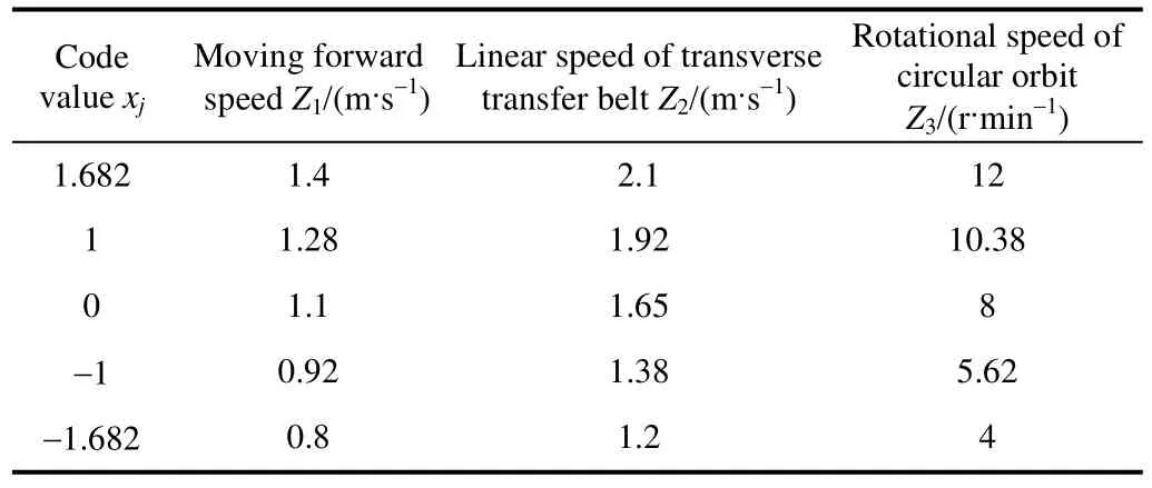
Table 1 Code values and levels of factors
The variance analyses of the regression model are presented in Table 3.
As shown in Table 3, according to the lack-of-fit test,since F11=1.511 7 and F12=2.450 3 were both less than F0.1(5,5)=3.45, the lack of fit was significant at the level of α=0.01 because F21=7.580 8 and F22=10.976 1 were both higher than F0.01(9,10)=4.94; the regression equation was significant at the level of α=0.01; and the equation fit the experimental data well according to the F test of the regression coefficients, reaching a significance level of 0.1.According to the F-test table, the results showed that the values for the damage rate in the single term x2and the cross term x1x2were extremely significant, and those in the quadratic term x22and the cross term x2x3were also significant. Similarly, the test levels for the impurity rate in the single terms x1and x3and the quadratic term x32were extremely significant, and those for the quadratic term x12and the cross term x2x3were also significant. According to the results of the significance test, eliminating the insignificant factors, the models of the performance index as functions of the experimental factors are as follows:
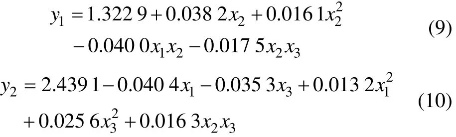

Table 2 Experimental project and results

Table 3 Variance analysis of regression model of damage rate and impurity rate
The test of the regression coefficients of equations (9)and (10) indicated that the following factors influence the damage rate, in decreasing order: the rotational speed of the circular orbit, the linear speed of the transverse transfer belt and the moving forward speed. The following factors influence the impurity rate, in decreasing order: the rotational speed of the circular orbit, the moving forward speed and the linear speed of the transverse transfer belt.
To analyze the effects of pairs of factors on the evaluation index, we conducted a two-factor interactive analysis of the test results by the dimension-reduction method[26,29]. The relationships between the damage and impurity rates and various factors are shown in Fig.8.
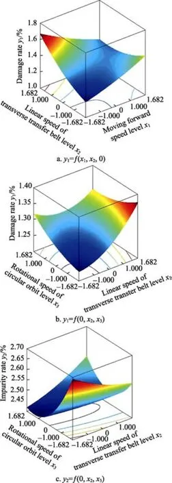
Fig. 8 Influence of interaction terms on experimental index
1) Discussion of the effects of interaction terms on the damage rate
When analyzing the influence of the interaction between the moving forward speed x1and the linear speed of the transverse transfer belt x2on the damage rate y1, we set the rotational speed of the circular orbit x3to 0. The influence of the interaction between the moving forward speed and the linear speed of the transverse transfer belt on the damage rate is plotted in Fig.8a. The areas of relatively low damage rate appeared when both the moving forward speed and the linear speed of the transverse transfer belt were near -1.682. When the moving forward speed is fixed,the damage rate will gradually increase with increasing linear speed of the transverse transfer belt. When the linear speed of the transverse transfer belt is fixed, the damage rate will increase linearly with increasing the moving forward speed. The moving forward speed and the linear speed of the transverse transfer belt needed to match reasonably well for the increase to occur. In the interaction between the moving forward speed and the linear speed of the transverse transfer belt, the latter is the main factor influencing the damage rate.
When analyzing the influence of the interaction between the linear speed of the transverse transfer belt x2and the rotational speed of the circular orbit x3on the damage rate y1, we set the moving forward speed x1to 0. The influence of the interaction between the linear speed of the transverse transfer belt and the rotational speed of the circular orbit on the damage rate is plotted in Fig.8b. When both the linear speed of the transverse transfer belt and the rotational speed of the circular orbit were -1.682, the damage rate was the lowest. When the linear speed of the transverse transfer belt is fixed, the damage rate will increase gradually with increasing rotational speed of the circular orbit. When the rotational speed of the circular orbit is fixed, the damage rate will increase rapidly with increasing linear speed of the transverse transfer belt. In the interaction between the linear speed of the transverse transfer belt and the rotational speed of the circular orbit, the former is the main factor influencing the damage rate.
2) Discussion of the effects of interaction terms on the impurity rate
When analyzing the influence of the interaction between the linear speed of the transverse transfer belt x2and the rotational speed of the circular orbit x3on the impurity rate y2, we set the moving forward speed x1to 0.The influence of the interaction between the linear speed of the transverse transfer belt and the rotational speed of the circular orbit on the impurity rate is plotted in Fig.8c. When the linear speed of the transverse transfer belt was -1.682 and the rotational speed of the circular orbit was 1, the damage rate was the lowest. When the linear speed of the transverse transfer belt is fixed, the impurity rate will initially decrease gradually and then increase slowly with increasing rotational speed of the circular orbit. When the rotational speed of the circular orbit is fixed, the impurity rate will initially decrease gradually and then increase slowly with increasing linear speed of the transverse transfer belt. In the interaction between the linear speed of the transverse transfer belt and the rotational speed of the circular orbit, the latter is the main factor influencing the impurity rate.
4.5 Optimization of the working parameters
According to the performance requirements of the potato combine harvester, the regression equations of the performance index of the damage and impurity rates are taken as the index. The main objective-function method was used with Matlab software to optimize the solution,achieving improved parameter-combination schemes under different objective functions[29-31].
The optimization model can be obtained when the damage rate is used as the objective function:

Another optimization model can be obtained when the impurity rate is used as the objective function:

The optimum parameter combinations are presented in Table 4.

Table 4 Optimum parameter-combinations for different objective functions
Considering the importance of the index of damage rate,the values of the optimum parameters are: The moving forward speed of 1.1 m/s, the linear speed of transverse transfer belt of 1.5 m/s and the rotational speed of circular orbit of 7 r/min, which leads to damage and impurity rates of 1.28% and 2.41%, respectively.
4.6 Verification experiment
To adjust the testing field for the potato combine harvester to the optimum parameters, in the case of the same test conditions above, measure the differences in the damage and impurity rates of several experiments, and fit the results by theoretical analysis, the selected performance index are an average damage rate of 1.46% and an average impurity rate of 2.57%, under the conditions of moving forward speed of 1.1 m/s, linear speed of transverse transfer belt of 1.5 m/s and rotational speed of circular orbit of 7 r/min. Compared with the index of the potato combine harvester (damage rate≤2% and impurity rate ≤4%), these performance index meet the technical requirements. The relative errors in damage rate and impurity rate were no more than 0.18 percentage point and 0.16 percentage point, respectively,compared with the optimal results. This was within the allowable range; therefore, the optimal results were reliable.
5 Conclusions
1) Through a quadratic general rotary regression analysis, a nonlinear regression model was established. This model illustrates the relationship among the moving forward speed, the linear speed of the transverse transfer belt, the rotational speed of the circular orbit and the damage and impurity rates. This lays a theoretical foundation for the development of a new separating and conveying device and potato combine harvester.
2) The factors affecting the damage rate, in decreasing order of influence, are the rotational speed of the circular orbit, the linear speed of the transverse transfer belt and the moving forward speed. The factors affecting the impurity rate, in decreasing order of influence, are the rotational speed of the circular orbit, the moving forward speed and the linear speed of the transverse transfer belt.
3) It is concluded that the optimal parameters for the potato combine harvester are a the moving forward speed of 1.1 m/s, a linear speed of the transverse transfer belt of 1.5 m/s and a rotational speed of the circular orbit of 7 r/min.Implementation of these parameters led to damage and impurity rates of 1.28% and 2.41%, respectively.
4) The performance index, verified through experiment,are an average damage rate of 1.46% and an average impurity rate of 2.57%. Compared with the index of the potato combine harvester (damage rate ≤2% and impurity rate ≤4%), these performance index meet the technical requirements.
[1] State Statistical Bureau. China Statistical Yearbook[M].Beijing: China Statistics Press, 2016.
[2] Liu Jianjun, Deng Mingli, Jia Shitong. The present situation of potato harvester and its development trends [J]. Journal of Agriculture, 2015(1): 95-99. (in Chinese with English abstract).
[3] Shi Mingming, Wei Hongan, Liu Xing, et al. The present situation of potato harvester development at home and abroad[J]. Journal of Agricultural Mechanization Research,2013, 10: 213-217. (in Chinese with English abstract).
[4] Wang Yanjun. Research on Separating and Conveying System of the 4M-2 Potato Combine Harvester[D]. Lanzhou:Gansu Agricultural University, 2007. (in Chinese with English abstract).
[5] Hosainpour A, Komarizade M H, Mahmoudi A, et al. High speed detection of potato and clod using an acoustic based intelligent system[J]. Expert System with Applications, 2011,38(10): 12101-12106.
[6] Wu Jianmin, Li Hui, Sun Wei, et al. Design of potato digger in poke finger’s wheel type[J]. Transactions of the Chinese Society for Agricultural Machinery, 2010, 41(12): 76-79.(in Chinese with English abstract).
[7] Platt H W, Campbell A J, Birt I M. Modifications of potato harvester for small plot field research[J]. Am Potato J, 1990,67(1): 799-803.
[8] Wei Hongan, Wang Di, Lian Wenxiang, et al. Development of 4UFD-1400 type potato combine harvester[J].Transactions of the Chinese Society of Agricultural Engineering (Transactions of the CSAE), 2013, 29(1): 11-17. (in Chinese with English abstract).
[9] Grimme Landmaschinenfabrik GmbH & Co. KG. Separating device for a potato harvester: US2015321225 [P].2015-11-12.
[10] Feng Q C, Zhao C J, Jia K, et al. Design and test of tray-seedling sorting transplanter[J]. Int J Agric & Biol Eng,2015, 8(2): 14-20.
[11] Mosalanejad H, Mobli H, Poursoltan A. The main parameters assessment of clod and stone separation from potato crop(inclined belt type) in potato harvester[J]. International Journal of Advanced Design and Manufacturing Technology,2011, 3(2): 79-84.
[12] Lu Xianghui, Wang Xin, Zhang Wenjie, et al. Parameter analysis and experiment for separation conveyer of 4U-1400 type potato harvester[J]. Journal of China Agricultural University, 2015, 20(6): 269-276. (in Chinese with English abstract).
[13] Li Baofa. Agricultural Mechanics [M]. Beijing: China Agriculture Press, 2003.
[14] Hu Zhichao, Peng Baoliang, Yin Wenqing, et al. Design and experiment on multifuctional root-tuber crops combine [J].Transactions of the Chinese Society for Agricultural Machinery, 2008, 39(8): 58-61. (in Chinese with English abstract).
[15] Jin Xin, Du Xinwu, Wang Shiguang, et al. Design and experiment of stems cutting device for carrot harvester [J].Transactions of the Chinese Society for Agricultural Machinery, 2016, 47(3): 82-89. (in Chinese with English abstract).
[16] Thoreson C P, Webster K E, Darr M J. Durability analysis of large corn stover briquettes[J]. Appl Eng Agric, 2012, 28(1):9-14.
[17] Kang Jing. The Design and Research on the 4U-1000 Potato Harvester[D]. Lanzhou: Gansu Agricultural University, 2014.(in Chinese with English abstract).
[18] Byler R K, Delhom C D. Comparison of saw ginning and high-speed roller ginning with different lint cleaners of mid-south grown cotton[J]. Appl Eng Agric, 2012, 28(4): 475-482.
[19] Wanjura J D , Faulkner W B, Holt G A, et al. Influence of harvesting and gin cleaning practices on southern high plains cotton quality[J]. Appl Eng Agric, 2012, 28(5): 631-641.
[20] Wang Jiasheng, Shang Shuqi. Development and experiment of double-row self-propelled carrots combine [J].Transactions of the Chinese Society of Agricultural Engineering (Transactions of the CSAE), 2012, 28(12): 38-43. (in Chinese with English abstract).
[21] Zhang W, Niu Z J, Li L H, et al. Design and optimization of seedling-feeding device for automatic maize transplanter with maize straw seedling-sprouting tray [J]. Int J Agric & Biol Eng, 2015, 8(6): 1-12.
[22] Gao G H, Feng T X, Yang H, et al . Development and optimization of edd-effector for extraction of potted anthurium seedlings during transplanting[J]. Appl Eng Agric,2016, 32(1): 37-46
[23] Yu Zhaoyang, Hu Zhichao, Wang Haiou, et al. Parameters optimization and experiment of garlic picking mechanism [J].Transactions of the Chinese Society of Agricultural Engineering (Transactions of the CSAE), 2015, 31(1): 40-46. (in Chinese with English abstract).
[24] China National Technical Committee of Standardization for agricultural machinery. document description: Potato harvester Non-book materials: NY/T 1130-2006 [S].Beijing: Standards Press of China, 2006: 7.
[25] Gao W, Tabil L G, Zhao R F, et al. Optimized design and experiment on ring mold pelletizer for producing biomass fuel pellets [J]. Int J Agric & Biol Eng, 2016, 9(3): 57-66.[26] Yi S J, Liu Y F, Wang C T, et al. Experimental study on the performance of bowl-tray rice precision seeder [J]. Int J Agric & Biol Eng, 2014, 7(1): 17-25.
[27] Yang Ranbing, Yang Hongguang, Shang Shuqi, et al. Design and test of poking roller shoving type potato harvester[J].Transactions of the Chinese Society for Agricultural Machinery, 2016, 47(7): 119-126. (in Chinese with English abstract).
[28] Ren Luquan. Optimum Design and Analysis of Experiments[M]. Beijing:Higher Education Press (HEP),2003.
[29] Singh R C, Singh G, Saraswat D C. Optimisation of design and operational parameters of a pneumatic seed metering device for planting cottonseeds[J]. Biosystems Engineering,2005, 92(4): 429-438.
[30] Yazgi A, Degirmencioglu A. Optimization of the seed spacing uniformity performance of a vacuum-type precision seeder using response surface methodology[J]. Biosystems Engineering, 2007, 97(3): 347-356.
[31] Singh M, Mahal H S, Sidhu G S, et al. Development and feasibility of innovative relay seeders for seeding wheat into standing cotton using a high clearance tractor in cotton-wheat system[J]. Appl Eng Agric, 2016, 32(4): 341-352.