Remote-controlledflexible pose measurement system and method for a moving target in wind tunnel
2018-02-02WeiLIUXinMALingCHENZhenyuanJIAWeixiaoLIUXiaoLIJiakunZHANGJiwenLU
Wei LIU,Xin MA,Ling CHEN,Zhenyuan JIA,Weixiao LIU,Xiao LI,Jiakun ZHANG,Jiwen LU
Key Laboratory for Precision and Non-traditional Machining Technology of the Ministry of Education,Dalian University of Technology,Dalian 116024,China
1.Introduction
The capability for military aircraft inflight to release external stores,such as weapons and auxiliary fuel tanks,when necessary is highly important.However,because of the interaction between the aerodynamic environment and the dynamic characteristics of the external stores,the released stores may collide with the aircraft,threatening the performance of the aircraft and the safety of the pilot.1,2
Simulative store separation experiments in wind tunnels provide valuable reference for the layout design and release parameters of the store.Among many research methods,the free drop method is one of the most typical experimental methods for store separation simulations in wind tunnels.The free drop method,with which the external store was ejected from the aircraft and fell down freely,and high-speed cameras were used to capture the trajectory of the external store,was widely used in simulative experiments forflight testing.However,since wind tunnel models usually have a large range of movement and rotation at high speeds and the measurement environment is more complex,traditional measurements fail to correctly measure their pose information.Photogrammetry(or videogrammetry)is a non-contact and efficient method for the measurement of model deformation,dimensions,and the position and attitude parameters of moving targets.Especially in complex measuring conditions,such as the underwater environment,outer space,and wind tunnels,photogrammetry is widely used.Therefore,pose measurement in wind tunnels based on vision measurement is of great importance.3,4
NASA Langley Research Center(LaRC)designed a multicamera videogrammetric system to measure model attitude in hypersonic facilities.5The technique utilized processed video data and applied photogrammetric principles for point tracking to compute the model’s position,including pitch,roll and yaw variables.Liu et al.proposed a position and attitude measurement method based on binocular vision for high-speed targets in wind tunnels.They performed measurement experiments for testing the release capability of aircraft in a wind tunnel and obtained high-precision results.6They then,in a subsequent paper,7proposed a position and attitude measurement method for wind tunnel models based on laser-aided vision technology.By using laser strips instead of reflective markers,a high-intensity light installed outside the wind tunnel is not required,which greatly improves the quality of the images because most of the redundant light reflected from the observation window can be avoided.In addition,other studies by the same authors proved that the use of selfluminous markers encoded inside the model helped to improve the brightness of image features and avoid the use of external lights.8Jia et al.proposed a position and attitude measurement method based on binocular vision.They obtained both the position and attitude of high-speedflying models;the measurement precision of displacement was less than 0.16 mm,that of pitch and yaw angles was less than 0.132°,and that of roll angle was 0.712°.9Others also studied intelligent and efficient measurement methods based on monocular vision.Graves and Burner developed an intelligent videogrammetric wind tunnel measurement system consisting of a digital CCD camera,a frame grabber,and a Personal Computer(PC).10The system can be useful and usable in measuring the deformation and attitude parameters of different models.The system features advanced pattern recognition techniques to improve automated location and identification of targets placed in the wind tunnel model,which greatly improves the intelligibility of visual measurements.Murray conducted experiments on position and attitude measurement of aircraft stores released from a payload bay at supersonic speeds in a trisonic wind tunnel.The store model has two collinear circular markers attached as image features.During the separation,a high-speed camera is utilized to acquire real-time images of the model,and the trajectory of the model,as well as its pitch and yaw angles,can be calculated based on the 2D information in those images.11Tanno et al.proposed a single camera method for the measurement of the complete 3D displacements and rotations of a free-flying model in a shock tunnel.12Among this research,the vertical and horizontal measurement ranges of most of the systems are small.Additionally,these systems are notflexible.In addition,the precision of the monocular vision pose measurement system is low.
As the number of internal and external model types increases and the required range of measurement during pose measurements becomes larger in high-production wind tunnels,it is important to improve the efficiency and flexibility of the position and attitude measurement.In this paper,we turn our attention to the development of aflexible position and attitude measurement technique.13,14Based on the precise location of the markers on the object surface,the position and attitude of the moving object can be computed using a single camera without knowing the camera focal length;therefore the camera focal length can be readjusted to ensure that high-quality images of different objects can be obtained during the measurement.Additionally,the camera orientation can be readjusted based on a transformation between the world coordinate system and the reference coordinate system in which the camera moves to ensure that the camera can obtain a properfield of view.Therefore,a flexible and efficient position and attitude measurement system is established for modern wind tunnels.
This paper is organized as follows:Section 2 introduces the overall measurement scheme for aflexible position and attitude measurement method and system for moving objects;Section 3 introduces the image acquisition and processing method in the wind tunnel;Section 4 introduces theflexible measurement principle without camera recalibration when the camera focal length or the camera orientation changes;Section 5 introduces the method for computing the position and attitude parameters;Section 6 describes the measurement experiments for moving objects in the laboratory as well as verification experiments for the measurement precision of the established system;Section 7 presents the study’s conclusions.
2.Flexible position and attitude measurement system and method
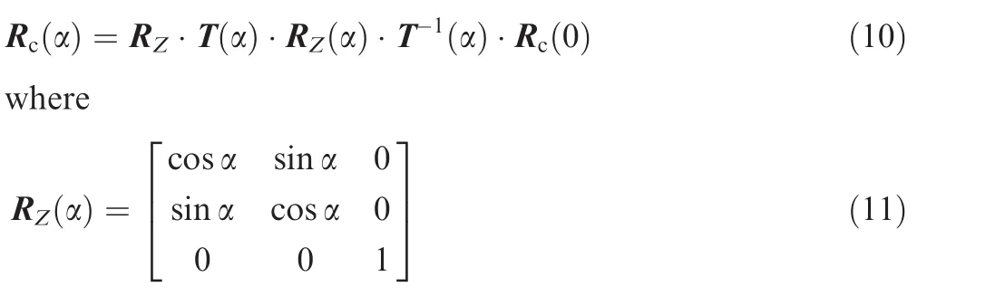
The principle of theflexible measurement method based on a single camera is shown in Fig.1.CCS is the camera coordinate system,and CMR is camera motion reference.TCS is the target coordinate system,and WCS is the world coordinatesystem. [Row, Tow]isthetransformation matrix between the TCS and the WCS.[Ro, To]is the transformation matrix between the TCS and the CCS.[Rc, Tc]is the transformation matrix between the CCS and the WCS.Markers arefirst attached at known positions in a TCS established on the object,where the object’s center of mass is the origin of the coordinate system.The view and the position of the camera can be controlled by a remotecontrolled system to make sure that the target is in thefield of view of the camera.The images of the moving object are captured by the single-view camera for milliseconds.Next,each of the markers is detected in the images using a color-recognition method to link them with their previously known coordinates on the object surface.The position and attitude of the target can be calculated when the pose of the camera and the intrinsic parameters of the camera are changed.A single camera algorithm is applied to each frame to calculate the rotation and translation matrixes between the single camera and the moving object without previous knowledge,as in traditional methods.The transformation matrixes between the CCS and the WCS are calculated before measurement.The position and attitude parameters of the object in the world coordinate system can befinally obtained through the single camera,which serves as a coordinate transmitter.
Theflexible position and attitude measurement system consists of a single camera,an electronic control platform and a controllable zoom lens as shown in Fig.2.The camera is positioned on the electronic control platform so that it can be controlled to translate and rotate to view the object.Thefield of view must be sufficient so as not to lose sight of the markers on the object when it is moving.To obtain images with high quality in case the object distance changes,some parameters of the zoom lens,such as the focal length,focus and aperture,must be adjusted remotely via a remotecontrolled system.

Fig.1 Flexible pose measurement method.
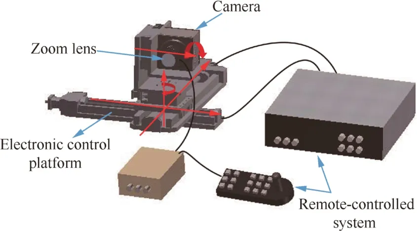
Fig.2 Flexible position and attitude measurement system.
3.Image acquisition and processing
To obtain the position and attitude of the target with the proposedflexible single camera method,a series of image processing procedures,such as image acquisition,feature recognition and extraction,are required.
The complexity of the wind tunnel environment has led to the following difficulties for the image acquisition method for high-speed models.(A)In the dark environment of wind tunnels,image acquisition of models was difficult because of the extremely low brightness.(B)The cameras should be installed at a slant angle against the observation window.Unfortunately,light would be easily reflected to the camera’s lens by the optical glass under such installation conditions,affecting the quality of image sequencing.(C)Each marker should be recognized based on the images.To facilitate this,some color self-luminous LEDs are installed on the target.A feature recognition method based on self-luminous LEDs in different colors is proposed in this paper to distinguish the markers in the 2D images.In addition,a feature extraction method based on the weighted gray distribution of the image is utilized to extract the centers of the 2D points.
Because there are some constraints for using a single camera method to calculate the position and attitude parameters of the object,markers detected on the images have to be linked with their previously known positions,as shown in Fig.3.A distinctive marker layout is designed and self-luminous LEDs in different colors are used to help identify each marker in the 2D image.The self-luminous markers on the object surface include white LEDs and several LEDs in different colors as shown.First of all,obtained images are processed by the background subtraction method as shown in Fig.4.Fig.4(a)shows the background image I1 without measured object.Fig.4(b)shows the actual measurement image I2 at the momentt.Fig.4(c)shows the image I after background subtraction,while I=I2-I1.And the specific color of a particular 2D point is identified based on a distance minimization method in the Red,Green,Blue(RGB)color space,where each of the colors has a specific coordinate.In the RGB color space,a specific color is judged to be the same as a known color if they have the smallest Euclidean distance between each other.The Euclidean distance between the value of a known color z(zR,zG,zB)and the detected value m(mR,mG,mB)of a 2D point is given by
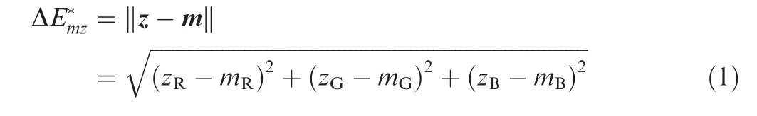
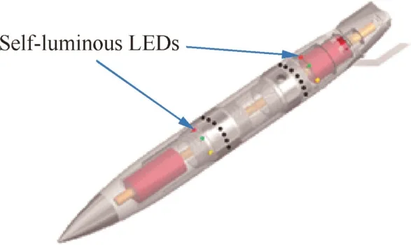
Fig.3 Markers’layout on measurement object.
where z is the RGB value of a specific known color,m is the RGB value of a detected 2D point,ΔE*mzis the Euclidean distance between the two colors,and the subscripts R,G and B are the components in the R,G and B channels of the colors,respectively.A detected color is determined to be a known one if they have the minimum ΔE*mz.
After all the colors of the colored points are recognized,others can be recognized based on the special markers’layout on the object.Therefore,the 2D points can be linked with their previously known 3D coordinates in the local coordinate system.Next,the centers of the 2D points are extracted using the gray centroid method.
4.Flexible pose measurement principle
As the number of internal and external model types increases in a wind tunnel experiment and the required range of measurement during pose measurements becomes larger in highproduction wind tunnels,it is important to improve the effi-ciency andflexibility of the position and attitude measurement.Therefore,a novel position and attitude measurement algorithm based on camera parameterization and a coordinate transformation method for the camera motion is proposed in this section.With this method,the focal length and the position of the camera can be adjusted both before and during the measurement without recalibration.Additionally,the pose information of the object can be calculated rapidly.
4.1.Algorithm for position and attitude estimation in case of changing focal length
To obtain the position and attitude parameters of the moving object,a single camera measurement method based on camera parameterization is used.The central innovative idea is to calculate the position and attitude of the object based on the information of markers that are distributed precisely at known locations on the object surface.15The main purpose of the proposed method is to calculate the rotation and translation matrix between TCS and CCS without camera calibration.Before the measurement,markers are attached onto the object surface based on a designed layout.A TCS is established in which the center of mass is the original point and the rotatory axis of the object isYaxis.The 3D coordinates of the markers in the TCS are given previously.
As shown in Fig.5,by assuming thatNmarkers on the object are observed by the camera,each of them has a corresponding point in the 2D image captured by the camera.Then,the projection relationship of the observed 3D point and its counterpart in the 2D image can be described as
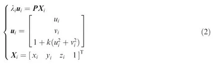
where λiis the scale factor associated with theith point,P the camera projection matrix,Xiis the 3D coordinate of theith marker on the object,[ui,vi]is the 2D coordinate of theith marker projected in the 2D image,andkthe distortion coefficient.The projection matrix P can be written as

In this case,K is known as the intrinsic matrix,R0is the rotation matrix and T0is the translation matrix between the TCS and the CCS.For most digital cameras,the pixels are square and the principal point is close to the center of the image.16Thus it can be assumed that the only unknown parameter in the camera intrinsic matrix is the camera focal lengthf.There-fore,K can be written as[f,f, 1]T.Assuming thatw=1/f,we have K= [1, 1,w]T.The scale factor λican be eliminated by multiplying Eq.(2)with [ui]×,so that Eq.(2)can be written as

Fig.4 Background image,foreground image and image obtained after background subtraction.
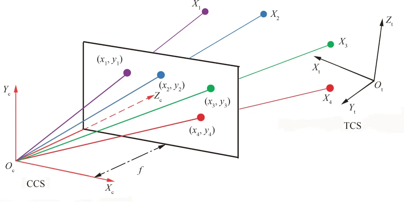
Fig.5 Camera and target 3D coordinate systems.
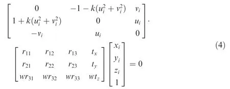
To obtain the position and attitude estimation of the moving object,we have tofind the solution P with Eq.(4).The elements in the projection matrix P can be defined aspij,which means the element in theith row and thejth column of P.Given the 3D coordinates[xi,yi,zi]4i=1of 4 non-collinear points on the object and their corresponding 2D coordinates [ui,vi]4i=1in the image,we can solve the problem described in Eq.(4).To solve Eq.(4),the projection matrix P is parameterized with only four unknowns(α1,α3,α3,k)by representing it using a linear combination of null space,15so that the unknowns of the equation can be reduced and we use constraints that the three rows of the 3×3 submatrix of the projection matrix P are perpendicular and that thefirst two rows of this submatrix have the same norm(see Eqs.(5)–(8)).This comes from the fact that thefirst 3 columns of P have the form KR.

Combining the above 4 equations,we can solve the 4 unknowns (α1,α3,α3,k),so that the projection matrix P can be solved and the rotation matrix R0and the translation matrix T0between the TCS and the CCS can be calculated according to matrix P.Next,we canfinish the position and attitude estimation of the moving object based on R0and T0.Finally,the Levenberg-Marquardt optimization algorithm is utilized tofind the optimal solutions to the above equations.Much work has been done to estimate absolute pose with unknown focal length.17,18In this paper,we select this algorithm to simplify the general solution problem to the non-planar solution problem and we can obtain much simpler systems of polynomial equations,so that the results are simpler and more practical.Then the Levenberg-Marquardt optimization algorithm is utilized tofind the optimal solutions to these polynomial equations.And the run-time is about 1 ms which is important for high-speed measurement.
4.2.Algorithm for position and attitude estimation in case of changing camera position
Another goal of theflexible measurement system proposed in this paper is that the position and attitude parameters of targets in the WCS can be obtained without camera recalibration after the camera orientation is changed.As shown in Fig.6,aflexible measurement method based on the transformation between the CMR and the WCS is proposed.XmandYmare the axis of the two translation platforms andZmandTmare the axes of the two rotation platforms.To calibrate the motion of the camera,a high-precision translation and rotation platform is utilized to ensure that the camera can be adjusted at known displacements and angles.Next,the camera is controlled to move on the platform many times tofind the transformation rule of the CMR relative to the WCS.Much work has been done to calibrate the camera motion parameters19,20normally with a planar target.In this paper,a high-precision target(calibration target)is used to calibrate these parameters,and this method is simple and low-cost.

Fig.6 Camera motion reference(CMR).
Because the camera is controlled to move on the translation and rotation platform,the reference for camera motion is the motion coordinate system which is established on the platform and the camera motion based on the platform can be obtained through the computer connected to the platform.The goal of this section is to transform the known motion of the camera to an unknown change of the CCS based on the WCS.In the general case,the camera can be controlled to translate alongXmandYmaxis of the translation platform and rotate aroundZmandTmaxes of the rotation platform.A translation coordinate system and two rotation coordinate systems are established.The method of transformation between the above CMRs and the WCSs will be described in detail.
4.2.1.Transformation method for camera displacement
4.2.2.Transformation method for camera rotation

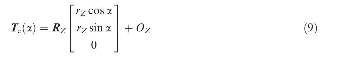
where Tc(α)is the translation matrix of the camera after it rotates.
The rotation matrix of the camera after it is readjusted aroundZmaxis of the platform is given by
In this case,Rc(α)is the rotation matrix of the camera in its new position,Rc(0)the rotation matrix of the camera in its original position,T(α)the translation vector of the camera center toOZ,and RZ(α)the rotation matrix between the camera and the ZCS.
Similarly,we can obtain the transformation matrixes of the camera after it rotates at an angle of β aroundTmaxis of the platform.
5.Calculating position and attitude parameters

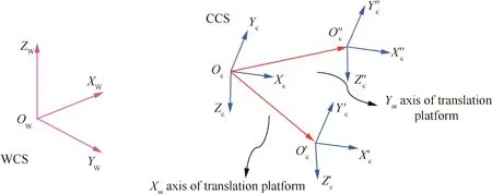
Fig.7 Principle of camera translation motion calibration.
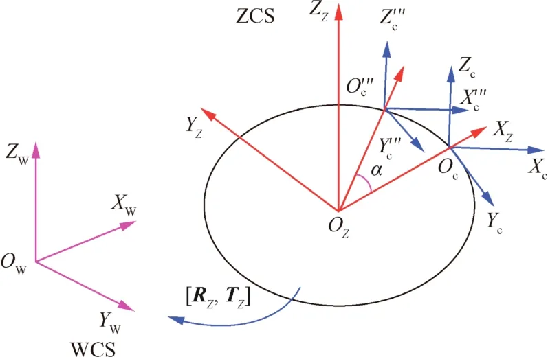
Fig.8 Principle of camera rotation motion calibration.
In Section 2,the translation matrix T0and the rotation matrix R0of the object at each moment are calculated,and the translation matrix Tcand the rotation matrix Rcof the camera in the WCS after it has been readjusted according to the requirements of the object are calculated in Section 4.Therefore,the transformation matrixes Rowand Towfrom the local coordinate system to the WCS can be calculated because both of the above can be transformed to the CCS.The translation vector of the object can be written as

whereXow,YowandZowarethecoordinatesoftheobject’scenter of mass in the WCS.According to the coordinate transformation principle,the rotation matrix is Row=RX(ψ)RY(φ)RZ(θ),in which

where RX(ψ),RY(φ)and RZ(θ)are the angles at which the object rotates aroundX,YandZaxes of the WCS,θ,φ and ψ represent the pitch,roll and yaw angle of the object,respectively.

Fig.9 Conversion relation between two coordinate systems.
6.Experimental analysis
6.1.Measurement system
As shown in Fig.10,the control system for the establishedflexible measurement system includes a camera orientation control system and a lens control system.The camera orientation control system mainly consists of a high-precision displacement and rotation platform.The platform can be controlled using an MC 600 control box and a computer,which help to realize a precise remote adjustment of the camera orientation.The lens control system consists of a controlling keyboard,a spot decoder,and a host computer that is not shown in Fig.10.Three micro motors are integrated in the zoom lens and mesh with the zoom ring,focusing ring,and aperture of the lens,respectively.The control instructions from the computer or the controlling keyboard are unscrambled by the spot decoder,controlling the micro motors.In this way,the focal length,focus and aperture of the camera lens can be easily changed via the computer,which can be controlled to change the focal length.
6.2.Measurement results and analysis
The position and attitude parameters of aflying object are measured in the laboratory with theflexible measurement system and method proposed in this paper.The camera was installed on the electronic control platform at approximately 1 m from the aircraft object from which the object will be separated,obtaining afield of view of 1000 mm×1000 mm.The camera was equipped with a 24–65 mm SATOO zoom lens that can be remotely controlled via a computer and was set at frame/2.0.Thefilm was taken at a frame rate of 1000 frame/s,which allows stopping the motion to obtain sharp images.The film resolution was 1280 pixel× 1024 pixel.The camera was controlled to translate along two directions and rotate around two axes of the electronic control platform whose displacement precision is 0.003 mm and whose rotation angle precision is 0.005°.During the measurement,the focal length of the camera is changed and the camera rotates 10°around theTaxis of the platform to capture the image of the measurement object.As shown in Fig.11,separation system can achieve the controllable separation,consisting of separation institutions and separation control system.
The measurement results given in Figs.12 and 13 show that the displacement of the object in three directions and the pitch,yaw,and roll angles of the object are detected.In this case,the displacements inXandYdirections represent the horizontal and vertical displacements,respectively.It can be concluded from Fig.12 that the object moves steadily in space and that the displacements of the pitch and roll angles of the object are almost the same during the measurement.The displacement inZdirection remains almost the same during the measurement.Itcan beobserved from Fig.13 thatthe displacement and rotation measurement results show excellent performance of theflexible measurement system in practical experiments.

Fig.10 Control systems for camera orientation and camera focal length.

Fig.11 Drop tank separation system and measurement object.

Fig.12 Displacements of center of mass as a function of time.
6.3.Precision verification experiments for system
To verify the position and attitude measurement accuracy of the proposed method and system,verification experiments are conducted in the laboratory to compare the measured parameters with previously known positions and attitudes of the object.As shown in Fig.14,a highly accurate electronic platform is utilized to carry out the verification experiment.The object isfirst mounted to an electronic platform whose displacement precision is 0.003 mm and whose rotation angle precision is 0.005°.Next,the object is controlled to carry out a translation of 10 mm via the platform.Meanwhile,the position information of the object will be measured by the measuring system.The precision of the measuring system can be estimated by comparing the measured results with the actual displacement of the object.The angle measurement precision of the system is estimated by comparing the measured results with the actual rotation(2°)of the object.
To verify the measurement accuracy of the established system for different objects,verification experiments for both planar objects and a certain type of aircraft store model are conducted.Precision verification results for a planar object are shown in Figs.15 and 16.28 sets of measurement experiments are conducted when the actual displacement of the object is 10 mm.It can be determined from thefigures that the mean deviation of the displacement measurement inXdirection is 0.2866 mm,while inYdirection it is 0.0938 mm;the mean deviation of the pitch angle measurement is 0.2615°,and the mean deviation of the yaw angle measurement is 0.1584°.The errors mainly come from errors in the posi-tional accuracy of the markers on the planar object and the extraction accuracy of the center of the markers.

Fig.13 Angles of object as a function of time.
Precision verification results for a store model are shown in Fig.17 and Fig.18.Approximately 18 sets of measurement experiments are conducted,where the actual displacement of the model is 10 mm and the actual rotation angle is 2°.It can be determined from thefigures that the mean deviation of the displacement measurement inXdirection is 0.3794 mm,while inYdirection it is 0.1544 mm;the mean deviation of the pitch angle measurement is 0.3624°;the mean deviation of the yaw angle measurement is 0.3311°.
Comparing the accuracy verification results of the planar object and the store model,it can be observed that the system has higher measurement accuracy for planar objects.Because the errors mainly come from errors in the positional accuracy of markers on the planar object and the extraction accuracy of the center of the markers,and the positional accuracy of markers on the planar object is higher than that on the store object in our experiments,the results are not surprising.There are three main factors affecting the accuracy of the measurement system:(A)the motion error of the electronic platform is thefirst factor that leads to poor measurement precision of the measurement system;(B)the machining error of the markers on the object surface is another one that decreases the precision;(C)the extraction accuracy of the markers is also impactive due to the factors such as small volume,surface profile of markers and random deformation during the rolling process.

Fig.14 Experimental setup for precision verification of system.
Fig.15 Precision testing results of displacement measurement for planar objects.

Fig.16 Precision testing results of angle measurement for planar objects.
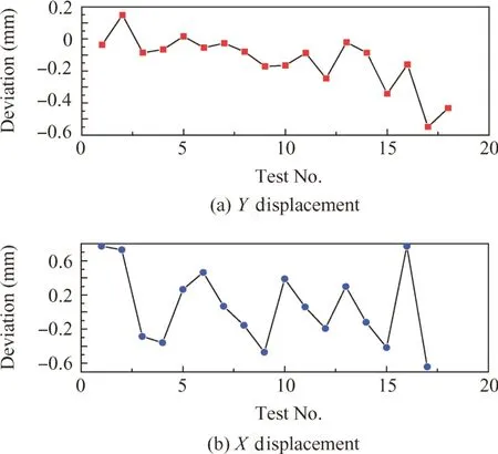
Fig.17 Precision testing results of displacement measurement for store model.

Fig.18 Precision testing results of angle measurement for store model.
Theprecision ofpresented measurementsystemsis between 0.1–0.2 mm6–8with smallmeasurementranges(1 m×1 m×1 m).However,the precision of the measurement system will decrease significantly when the target is beyond the measurement ranges.In this paper,though the precision of the method is relatively low,only one camera is needed in our measurement system,and the position and focal length parameters can be adjusted to satisfy theflexibility measurement requirement.Additionally,by using this cost-effective measurement system,the measurement ranges are increased.
7.Conclusions
Aflexible position and attitude measurement method and system for moving objects in a wind tunnel are proposed in this paper.This method overcomes the limitation of measurement distance along the optical axis of the camera and enlarges the measurement range in the test space.Both the camera focal length and the camera orientation can be readjusted without camera recalibration to meet the measurement requirements of different objects,highly improving theflexibility of modern visual measurement systems.
(1)A single camera method with unknown camera focal length is proposed to measure the position and attitude of the object.The position and attitude parameters of a moving object are obtained by utilizing a single camera with a focal length and camera orientation that can be changed based on different measurement conditions.
(2)Aflexible measurement method with which the camera orientation can be readjusted to view the object during the measurement without camera recalibration is proposed.The method is based on establishing the transformation model between the camera motion coordinate system and the WCS.The position and attitude of the object arefinally transformed to the WCS.
(3)A position and attitude measurement system for moving objects based on the proposed flexible measuring method is established.Measurement experiments and verification experiments for the measurement accuracy are conducted in the laboratory.Experimental results show that the accuracy of the displacement measurement for planar targets is 0.2866 mm and the accuracy of the attitude measurement for planar objects is 0.2615°,while the corresponding accuracy for small rolling targets is 0.3794 mm and 0.3624°,respectively.
Acknowledgements
This study was co-supported by the National Natural Science Foundation-Outstanding Youth Foundation of China(No.51622501),the National Natural Science Foundation of China(Nos.51375075 and 51227004),the Fundamental Research Funds for the Central Universities of China,and the Science Fund for Creative Research Groups of China(No.51321004).
1.Lee JJ,Ho HN,Lee JH.A vision-based dynamic rotational angle measurement system for large civil structures.Sensors2012;12(6):7326–36.
2.Marro´n-Romera M,Garcı´a JC,Sotelo MA,Pizarro D,Mazo M,Can˜as JM,et al.Stereo vision tracking of multiple objects in complex indoor environments.Sensors2010;10(10):8865–87.
3.Sibok Y,Brett N.Development of a high accuracy angular measurement system for langley research center hypersonic wind tunnel facilitiesProceedings of the 44th AIAA/ASME/ASCE/AHS/ASCstructures,structuraldynamics,andmaterialsconference.Reston:AIAA;2003.p.5168–78.
4.Park HS,Kim JY,Kim JG,Choi SW,Kim Y.A new position measurement system using a motion-capture camera for wind tunnel tests.Sensors2013;13(9):12329–44.
5.Jones TW,Lunsford CB.Design and development of a real-time model attitude measurement system for hypersonic facilitiesProceedings of the 43rd AIAA aerospace sciences meeting and exhibit.Reston:AIAA;2005.p.5489–98.
6.Liu W,Ma X,Jia ZY,Zhang Y,Shang ZL,Li X.Position and attitude measurement of high-speed isolates for hypersonic facilities.Measurement2015;10(62):63–73.
7.Liu W,Ma X,Li X,Zhang Y,Shang ZL,Li XD.High-precision pose measurement method in wind tunnels based on laser-aided vision technology.Chin J Aeronaut2015;28(4):1121–30.
8.Liu W,Shang ZL,Ma X,Zhang Y,Li X,Jia ZY.Position and attitude measuring of auxiliary fuel tank based on color-coding in wind tunnel.Acta Aeronaut Astronaut Sin2015;36(5):1556–63[Chinese].
9.Jia Z,Ma X,Liu W,Lu WB,Li X,Chen L,et al.Pose measurement method and experiments for high-speed rolling targets in a wind tunnel.Sensors2014;14(12):23933–53.
10.Graves SS,Burner AW.Development of an intelligent videogrammetric wind tunnel measurement system.Proc SPIE–Int Soc Opt Eng2001;2001(4448):130–1.
11.Murray N,Jansen B,Gui L,Seiner J,Birkbeck R.Measurements of store separation dynamicsProceedings of the 47th AIAA aerospace sciences meeting including the new horizons forum and aerospace exposition.Reston:AIAA;2009.p.105–14.
12.Tanno H,Komuro T,Sato K,Fujita K,Laurence SJ.Free-flight measurement technique in the free-piston high-enthalpy shock tunnel.Rev Sci Instrum2014;85(4):045112.
13.Wang JQ,Xiong K,Zhou HY.Low-frequency periodic error identification and compensation for star tracker attitude measurement.Chin J Aeronaut2012;25(4):615–21.
14.Zhai G,Zhang JG,Zhou ZC.Coordinated target localization base on pseudo measurement for clustered space robot.Chin J Aeronaut2013;26(6):1524–33.
15.Zhang Z,Zhu D,Peng Z,Zhang J.Improved iterative pose estimation algorithm using three-dimensional feature points.Opt Eng2009;46(12):127202.
16.Richard H,Andrew Z.Multiple view geometry in computer vision.Cambridge:Cambridge University Press;2000,p.5.
17.Fitzgibbon A.Simultaneous linear estimation of multiple view geometry and lens distortion.Anne J,Thomas B,editors.Stereo vision and structure recovery.Proceedings of the 2001 IEEE computer society conference on computer vision and pattern recognition.Piscataway:IEEE Press;2001.p.125–31.
18.Josephson K,Byro¨d M,Astro¨m K.Pose estimation with radial distortion and unknown focal length.In:Pat F,Eric M,editors.Computational photography and video.Proceedings of the 2009 IEEE computer society conference on computer vision and pattern recognition.Piscataway:IEEE Press;2009.p.2419–26.
19.Wei Z,Sun W,Zhang G,Ren S.Global calibration method for laser-tracking measurement system based on vision guiding.Chin J Sci Instrum2009;30(11):2262–7.
20.Sun W,Wei Z,Cao L.A triple-laser trackers automatic measurement system for large-scale parts assembly ICEMI.In:Cui JP,Qi JM,editors.Electronic measurement&instruments.Proceedings of the 9th international conference on electronic measurement&instruments.Piscataway:IEEE Press;2009.p.540–3.
杂志排行

CHINESE JOURNAL OF AERONAUTICS的其它文章
- Multi-mode diagnosis of a gas turbine engine using an adaptive neuro-fuzzy system
- PHM with Aerospace Applications
- A critique of reliability prediction techniques for avionics applications
- Reduction rules-based search algorithm for opportunistic replacement strategy of multiple life-limited parts
- Satellite lithium-ion battery remaining useful life estimation with an iterative updated RVM fused with the KF algorithm
- A Bayesian approach for integrating multilevel priors and data for aerospace system reliability assessment