Low Velocity Impact Response and Failure Assessment of Textile Reinforced Concrete Slabs
2018-01-23SushiniSmithGopinthndAhrthy
Sushini I, Smith Gopinth* nd Ahrthy R
1 Introduction
Reinforced concrete structures are designed for safety and serviceability. Due to brittleness of concrete, impact damage is a major cause of reduction in life span of any concrete construction. To overcome this, we are in need of cementitious composites with more toughness, i.e., having the ability to absorb energy and plastically deform without fracturing. In practical situations, many concrete structures are subjected to short duration dynamic loads. The need for higher impact resistance in many such structural components had led researches to investigate the energy absorption of various composite materials at high impact loads as an alternate solution [Prakash et al. (2014); Safri et al.(2014)]. A recent development in this line is the Textile reinforced concrete (TRC),which is a construction material that is used for structural and non- structural applications. In TRC, non-metallic textiles are used as reinforcement and a fine grained cementitious binder is used as matrix. The use of textile is found to be advantageous in impact conditions for energy absorption. Daskiran et al. (2016) examined nine ready mix repair mortars commonly used in construction industry for high performance of textile reinforced cementitious composite and designed fine grained concrete matrices modified with polymer additives. Results showed that fine grained concretes with polymer additives had higher flexural strength than ready mix repair mortars at 28 days; some of the ready mixed repair mortars used for producing TRC have potential reactivity due to alkali silica reaction and some of them didn’t show sufficient flexural performance.
Generally, when impact load is applied to a concrete structure, various forms of damages will be occurred during the loading process. The most common damages are the different types of global or localized damage, including flexural cracking, shear cracking,crushing of concrete beneath the projectile and spalling at the bottom of a concrete element. Moreover, in order to ascertain a reliable impact-resistant design procedure, a series of practical tests are required. Husem and Cosgun (2016) analyzed RC plates of three different sizes and at two different support conditions under impact loading using ABAQUS finite element software with Concrete Damage Plasticity Model (CDP) for concrete and Classical Metal Plasticity Model (CMP) for reinforcing steel. Results from RC plate experiments in literature are found to be similar with the results of numerical analysis. The behaviour of reinforced concrete members under impact load has been experimentally observed by Hrynyk and Vecchio (2014), Hao, et al. (2016), Choong et al.(2011), Chen et al. (2011) and Zhu et al. (2009). It is difficult to study the behaviour of structure in full-scale under impact loading since it requires high cost equipments and time to perform. With regard to this, Mokhatar and Abdullah (2012) used the finite element analysis in order to predict the low velocity impact response of reinforced concrete elements with reasonable accuracy. TRC being a relatively new construction material, which has gained significance recently, simulation studies under impact loading are scanty as of today. Especially, when the behaviour after reaching the maximum impact resistance is of interest, it is necessary to have accurate models that predict the progressive failure in such composites.
In finite element method (FEM), there are some advantages and disadvantages, which strictly depend to a large extent on its particular application. Anil Kantar and Yilmaz(2015), Mokhatar et al. (2013), Smitha et al. (2013), Sinaei et al. (2012), Kishi et al.(2011), Farnam et al. (2010) and Tahmasebinia and Remennikov (2008) have used finite element analysis to predict impact response of various concrete slabs. Some of the difficulties in such analysis are in generating or regenerating a quality mesh to assess the failure pattern, which are defined on meshes of data points. In such meshes each point has a fixed number of predefined neighbors and the connectivity between them can be used to define the mathematical operators. During the simulation under extreme deformation of the material it is difficult to maintain the mesh without distortion and without introducing error that leads to wrong values in result. The mesh may be recreated during simulation but this can also give error in analysis. To avoid this problem the meshless method is generally preferred. Mokhatar et al. (2013) have successfully applied mesh free method to study the behaviour of reinforced concrete members under impact test or loading. Numerical simulations of concrete members have also been presented by Liu and Liu (2003).
In order to combine the advantage of finite element method and meshless method,Smoothed Particle Hydrodynamics (SPH) can be thought as a solution to assess the failure pattern. In recent years, application of SPH has been widely used for the low and high velocity impact computation. Verma et al. (2016) concluded that FEM with SPH particle conversion was found to emulate fragmentation due to impact. Moreover, the element converted to particles based on strain criteria had given idea about the crack propagation. However, investigations based on the coupling of finite element and SPH model have not been done so much yet. Therefore, in this study the finite element method is coupled with SPH to simulate the behaviour of TRC slabs under low velocity impact loading.
From safety and reliability point of view, a two parameter Weibull distribution was used to determine the impact resistance and the energy impact of the specimens by Bedi and Rakesh (2009), Chen and May (2009) and Sakin and Irfan (2008). Perumal (2013)developed multiple linear regression model to predict the ultimate failure resistance and it is found to provide results in good correlation with the experimental results, where 95% of the estimated values are within ± 5% of the actual values. When the reinforced concrete is subjected to low velocity impact test or loading by drop weight impact it will dissipate some energy through the instrument and will absorb some energy through the crack developed as discussed in Abdulrahman and Al-Ejbari (2012). The model is considered to be effective in predicting impact resistance and energy of the specimen as suggested by the researchers Murali et al., (2014). Erdem (2014) developed Artificial Neural Network (ANN) analysis to predict acceleration and impact force. Depending on the correlation coefficients obtained it is found that a strong relationship have been established between test and predicted values. Since it takes time to perform tests in laboratory conditions, efforts are being taken to find alternative ways to predict the test data.
This present paper reports about the simulation of TRC slabs under impact by combining finite element method with smoothed particle hydrodynamics. In addition, development of a probability based model to predict the impact resistance for various percentage textile reinforcement in TRC slabs towards assessing the failure in terms of reliability and safety limits is also reported.
2 Nonlinear analysis of TRC slabs under impact load using FEM and SPH
Numerical analysis has been carried out by combining finite element method with smoothed particle hydrodynamics to simulate the response of TRC slabs under low velocity impact loading. A finite element model was created and explicit dynamic analysis of the low-energy impact was carried out on TRC slabs. Generally, when impact load is applied to a structure, various forms of damages can be seen during the loading process. To simulate this, an automatic conversion of FEM to SPH particle option was used. The damaged particles in SPH are tracked for predicting the overall damage to the specimens.
2.1 Details of the slab
A square TRC slab of size 450 x 450 mm with thickness of 50 mm is modeled and analysed using finite element analysis software (Fig. 1). The slabs are reinforced with 5 layers (G-5) and 10 layers (G-10) of glass textiles. Eight noded solid linear brick elements C3D8R (Cube Three Dimensional eight node Reduced Integration) with 3 degrees of freedom at each node with hourglass control were assigned to TRC binder.Concrete Damaged Plasticity model which incorporates the elasticity, plasticity and compressive behaviour of concrete was incorporated to express the heterogeneity of the binder. The impactor part is created as a steel part with the mass density, elastic and plastic property of material as shown in Tab.1. The impactor having mass of 9.155 kg is allowed to hit the TRC slab with velocity ranges from 3.3m/s to 7.4m/s corresponding to the energy level from 50J to 250J. Boundary condition for TRC slab is assumed as simply supported in the analysis. A homogeneous and deformable wire beam element is created as textile yarn. It is assembled in horizontal and vertical direction to form textile reinforcement. The textile is embedded in the slab by using embedded constraints so that it acts as a single solid body under impact. The grid spacing in textile is 25mm whereas the spacing between textiles is taken as 1mm to replicate the actual experimental conditions used in casting. The entire slab along with textile is meshed with element size of 5 mm near impactor, which gradually increases to 25 mm. In the analysis, the energy absorption of slab under the impact load is determined and is compared with the experimental results for validation.
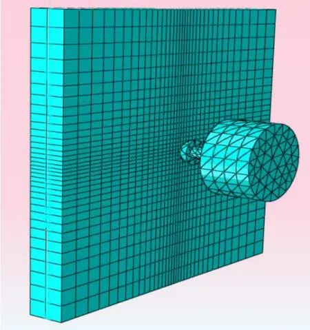
Figure 1: FEM model for impact analysis of TRC slab
2.2 Details of material properties
Constitutive behaviour of concrete is very tedious to capture by using elastic damage models or elastic plastic laws since irreversible strains cannot be captured. On the other hand when elastic plastic relation is adopted the strain will be overestimated since the unloading curve will follow the elastic slope. Concrete Damage Plasticity (CDP) model combines these two approaches can capture the constitutive behaviour of experimental unloading. In this model two main failure mechanisms are assumed: tensile cracking and compressive crushing of the concrete as shown in Tab. 1. In addition, the degradation of material in both tension and compression has been reflected in this model. The stress strain curves from experimental investigations are assigned as input for concrete damaged plasticity model. The evolution of the yield surface is controlled by tensile and compressive equivalent plastic strains. In this model all the parameters are validated with the experimental results. A plastic damage model for concrete subjected to cyclic loading is developed using the concept of fracture-energy based damage. The amount of energy absorbed is studied by the simple post processing. The constants are validated with the experimental results.
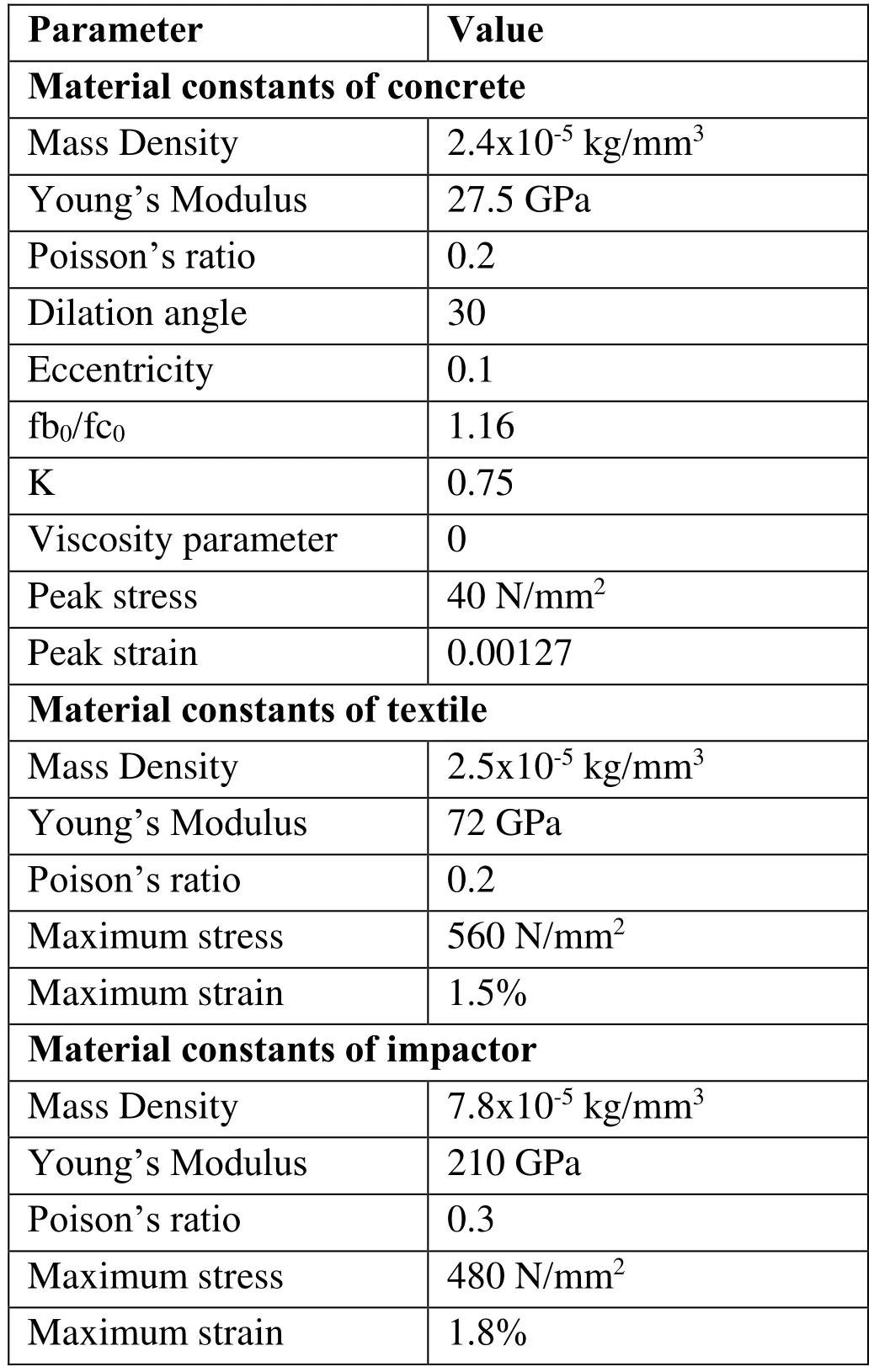
Table 1: Various material parameters used in modelling
Von-Mises criterion was applied for textile reinforcement for the constitutive modelling.The CDP model of concrete and the Von-mises model of textile maintain the homogeneity of the structure so that the behaviour of two different materials under the cyclic loading will be similar. The material properties were assigned as given by manufacturer. The various material properties used are given in Tab. 1.
The impactor used in the finite element analysis is modeled as a steel part which has the material constant as shown in Tab. 1. During the process the impactor is provided with an amount of energy for the simulation of instrumented impact test.
2.3 Smoothed particle hydrodynamics (SPH) for failure assessment
SPH is a method to solve Partial Differential Equations (PDE). It is one of the numerical meshless methods or mesh free method for which nodes and elements are not defined.This method divides the continuum into a set of particles and uses Lagrangian formulation of deformation together with dynamic explicit of time integration, which is conditionally stable. This particle collective method is defined to represent a given body,wherein particles have a characteristics length over which the material properties are smoothed by a kernel function. The kernel has a value of one at its centre and zero at the perimeter, with the result that each particle interacts only with particles within its kernel radius. This is used to avoid further numerical difficulties that are faced during the extreme deformations in FEM.
2.4 Results & discussion
Along with the mesh part SPH is also used to define the behaviour of the model in detail with respect to strain. The element allows for transverse shear deformation, which is important in simulating elements. The element also accounts for finite strain and is suitable for large strain analysis. While incorporating SPH, it is needed to provide a threshold strain. Once an element reaches this threshold strain, it is converted into particle. Hence it is able to analyse elements with larger distortion. For arriving at threshold value, trial models were created and analyzed using FEM and the minimum strain value is noted and the respective models were validated with the experiment value.From the experiment, the threshold strain used was 0.001. Further, Fig. 2 shows the visualization module in slabs analysed with and without SPH. In comparing energy absorption of slabs analysed using FEM with and without SPH, it is found that simulation of model with 10 layers of textile with SPH shows better results (Figs. 3 and 4). SPH shows a detailed behaviour of all elements in the slab part when subjected to impact load. The numerical results are also validated with the experimental results.
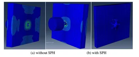
Figure 2: Visualization module
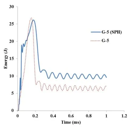
Figure 3: Energy absorption of 5 layers TRC slab with and without SPH
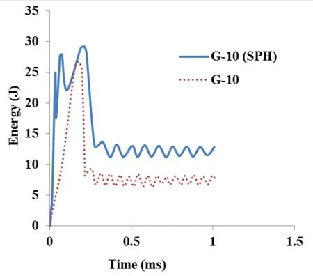
Figure 4: Energy absorption of 10 layers TRC slab with and without SPH
3 Experimental validation
The Textile Reinforced Concrete slabs with 5 and 10 layers of glass textile are cast at the laboratory following the standard procedure. Initially the binder is filled upto half the thickness of slab; then the textile layers are placed altogether such that they are in the middle position; subsequently the final layer of binder is filled. Three specimens were cast for conducting test in each type. Instrumented impact test was carried out on TRC slabs using Instron CEAST 9350. The slabs were clamped to prevent the rebound behaviour at the time of impact. The slabs are provided with simply supported boundary condition. Based upon several trials on specimen with lower energies in the range interval of 10J, it is observed that it doesn't cause much damage/crack to the specimen till 50J. Hence for the further studies, the impactor is allowed to hit the slab with energy ranging from 50 J to 250 J.
Due to the existence of inertial loads, the observed load from the tup may not give the actual bending load (Bindiganavile and Banthia, 2001). Therefore, to arrive at the actual bending load (Pb(t)) on the specimen, it is needed to subtract the generalized inertial load(Pi(t)) from the measured hammer load (Pt(t)) as given in Eq. 2. The inertial load, Pi(t), is calculated by using the principle of virtual work. For simply supported boundary condition, knowing the accelerations along the length of the beam, the distributed inertial forces can be replaced by a generalized inertial load Pi(t) acting at the centre (Banthia et.al, 1989) and is given by the following equation


Thus the actual bending load is calculated for all the slab specimens and the force time histories were plotted.
From the experimental results it was observed that the impact resistance and energy absorption of TRC slabs with 10 layers of glass textile is relatively more than that of TRC slabs with 5 layers of glass textile (Fig. 5). The textile undergoes rupture with increase in impact loading. The Figs. 6 and 7 shows that the maximum energy absorption of 5 layers and 10 layers TRC slab obtained from experiment is well validated with the results obtained from the nonlinear analysis. The peak values for numerical and experimental results are fairly close thus proving that the numerical simulations can be further used for various numbers of layers of textile.
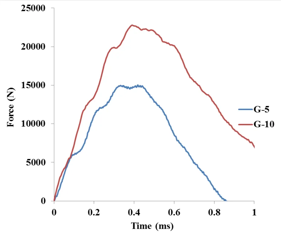
Figure 5: Impact force history of TRC slabs
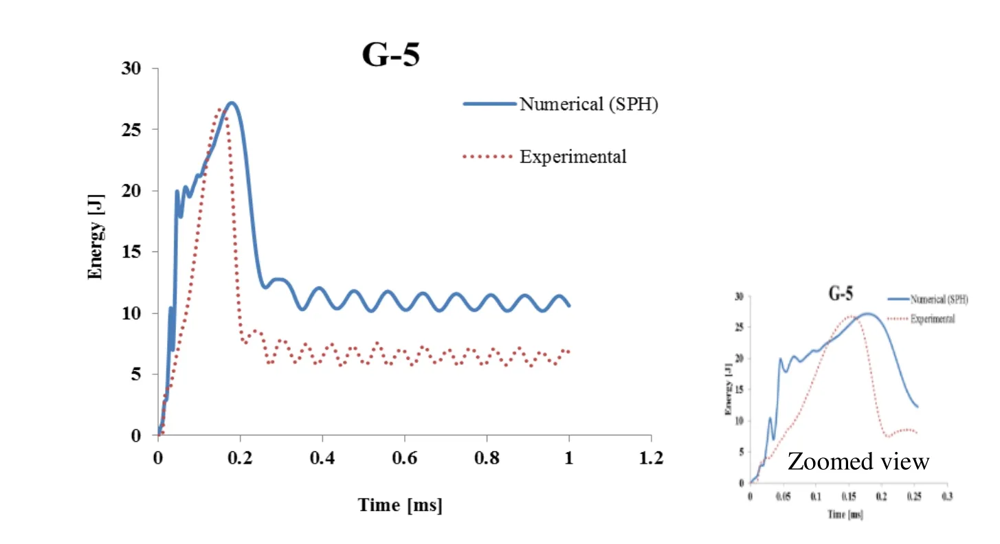
Figure 6: Energy absorption of 5 layer TRC slab
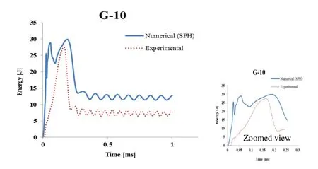
Figure 7: Energy absorption of 10 layer TRC slab
3.1 Damage evaluation
The damage pattern observed in the specimen tested experimentally and that obtained from numerical analysis was compared. Since the damages observed were very minimal at lower energy levels, a typical case of 100J is chosen as the common energy level for the damage analysis. The failure pattern was observed as radial which indicates the equal distribution of load over the specimen. The textile undergoes rupture with increase in impact loading. The damaged area is observed to be more in glass textile reinforced concrete slab with 10 layers of textile at maximum impact load since it absorbs more energy. Fig. 8 shows the typical damage pattern observed in glass textile reinforced concrete slab at 100J (experimentally and numerically).

Figure 8: Damage pattern (G-5 at 100J)
4 Weibull distribution for failure assessment
Investigations were also carried out using two parameter Weibull distributions to determine the impact resistance and the impact energy of the TRC specimens to assure the safety and reliability. Experiments were carried out on TRC slabs under repeated impacts and the data obtained are used for Weibull distribution. Ten numbers of specimens were tested under each category and the average value is taken. The Weibull equation describes the relationship between the probabilities of failure of impact. It thus predicts the impact resistance of concrete at failure. There are two important parameters in Weibull distribution i.e., scale and shape parameter. It is a continuous probability distribution. The probability density function of a Weibull random variable and the cumulative distribution function Ff(x)of Weibull probability are given in Eqs. 3 and 4 respectively.

where, β > 0 is the shape parameter and α > 0 is the scale parameter of the distribution.

where, x - Variable (blows) / Nf- Number of blow till failure; α - Scale Parameter, β –Shape Parameter Ff(x)- Probability of Failure (Px).
The test result shows that the number of blows increases with increase in reinforcement ratio as shown in Fig.9. The energy obtained at first crack and failure with respect to number of blows is shown in Tab.2 and Fig. 10. The energy determined under impact has been used to estimate the Weibull parameters. Linear Regression analysis is used to determine the shape and scale parameters of Weibull distribution. The scale and shape parameters are determined from Fig. 11. Several predefined empirical survivorship functions have been used in different sets of literatures for evaluating the value of LN.

Where, i is the failure order number and k is the total number of samples.
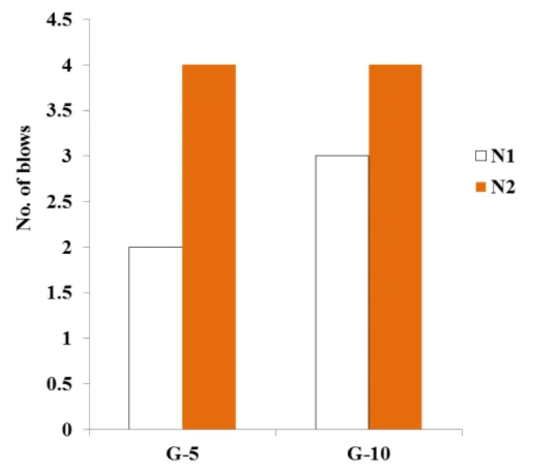
Figure 9: No. of Blows for first crack (N1) and failure (N2)
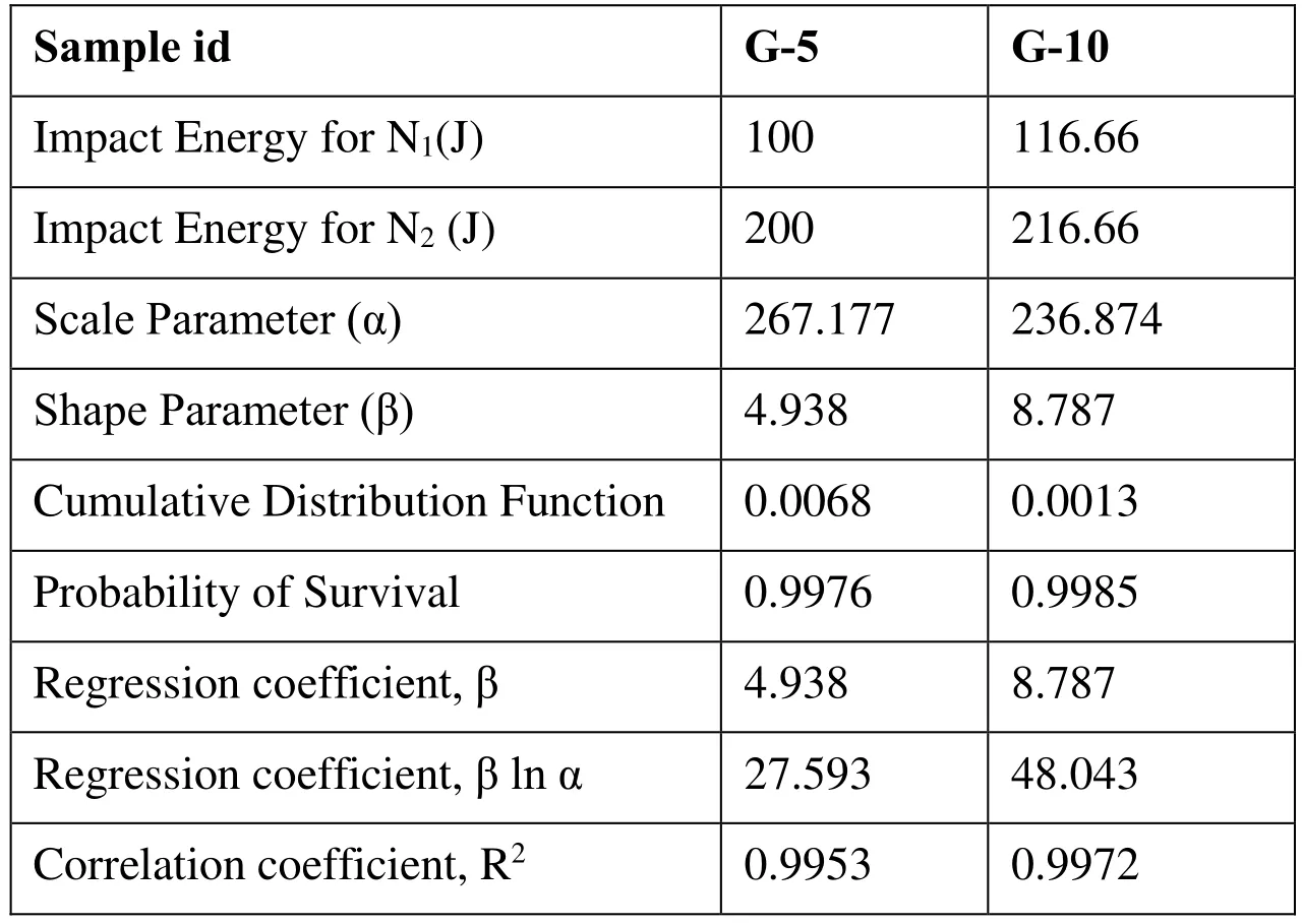
Table 2: Parameter details for Weibull distribution model development
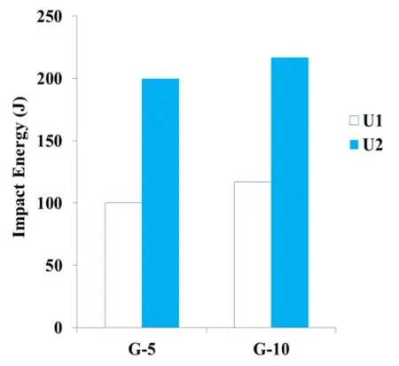
Figure 10: Impact Energy for N1 and N2
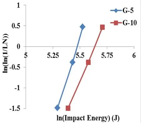
Figure 11: Linear regression of impact failure energy in weibull distribution
The slope of the line for G-5 andG-10 was 4.938 and 8.787 which corresponds to the value of shape parameter obtained from Fig.10Based on the graph the shape parameters are obtained from the slope of each specimen. The scale parameters are obtained by the formula,

The scale parameter for each specimen G-5 and G-10 is calculated as 267.177 and 236.874 respectively using the points at which the line intersects the Y-axis (-11.98 and -20.865 respectively).
Thus, both the scale and shape parameters are obtained for the Weibull distribution. The cumulative distribution function is calculated by Eq. 7. The probability of survival or reliability is calculated from the CDF as in Eq.8 and subsequently, the regression coefficients about β, β ln α and the correlation coefficient R2can be obtained by linear analysis and shown in Tab.2.

where, x is the variable (life), α is the characteristics life or scale parameter, Ff(x)/(Px) is the probability of failure and Fs(x) is the probability of survival or reliability (Rx).
The results shows that the G-10 slab have highest correlation coefficient compared to other type of specimens. Thus, the probability model results are in agreement with experimental results.
The probability of survival and URNdenotes the impact failure energy based on reliability.

Here, RNis the reliability level that ranges from 0.01 to 0.99. Based on this theoretical property, the nominal reliability value is 0.368. Therefore, 36.8% of the tested G-5 and G-10 specimens have an Impact failure energy value of at least 28.7 and 59.65J respectively. The impact failure energy based on the reliability level is shown in Fig. 12.From the figure it is proven that for increase in the reliability level or survival the impact energy of the specimen decreases that further indicates the impact resistance of specimen.
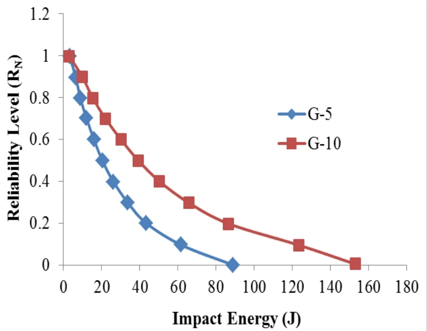
Figure 12: Impact Energy at Reliability level
5 Conclusion
In this paper the numerical, probability model and the experimental results for 5 and 10 layers textile reinforced concrete slabs under impact test were compared and validated. It shows that the 10 layered textile reinforced concrete slab has good energy absorption than the 5 layered slabs under impact.
• Numerical impact simulation is carried out using finite element analysis of a dynamic explicit model with and without incorporating SPH. The results obtained by incorporating SPH on textile reinforced concrete slabs showed better correlation with experimental data from instrumented impact test. The numerical impact models provide reasonable accurate details of instrumented impact on textile reinforced slabs that includes energy absorption with respect to time. SPH is found to be good at predicting failure modes in composites structures and further provides refinement of results for better correlations.
• The probability based model developed to predict the correlation coefficient and impact energy by weibull distribution method reveals that the increase in percentage of reinforcement increases the resistance of concrete under impact. The result shows that the slab with 10 layers of textile has more correlation coefficient which indicates more resistant towards impact.
• From the experimental results, it is found that the impact resistance and energy absorption is relatively more for slabs with 10 layers of textile than slabs with 5 layers of textile. The energy absorption is compared with numerical results and analytical model for both 5 and 10 layers of textile and found that a strong relationship have been established between test and predicted values. The failure pattern was observed as radial which indicates the equal distribution of load over the specimen. The damage pattern observed from numerical results is found to be similar with that of experimental results.
Acknowledgements:Authors thank the help provided by Dr. Amar Prakash, Scientist and Mr. Bhavani Harish, Project Assistant of CSIR-SERC for the experimental investigations.
Abdulrahman, A. I. A. H. A.; Al-Ejbari, A. D. A. T.(2012): Behaviour of Reinforced Polymer Modified High Strength Concrete Slabs under Low Velocity Impact.Anbar Journal for Engineering Sciences, pp. 171-189.
Anil, O.; Kantar, E.; Yilmaz, M. C.(2015): Low velocity impact behaviour of RC slabs with different support types.Construction and Building Materials, vol. 93, pp.1078-1088.
Banthia, N.; Mindess, S.; Bentur, A.; Pigeon. M.(1989): Impact testing of concrete using a drop-weight impact machine.Experimental Mechanics,vol. 29, no. 1, pp. 63-69.Bedi, Raman; Rakesh, Chandra.(2009): Fatigue-life distributions and failure probability for glass-fiber reinforced polymeric composites.Composites Science and Technology, vol.69, no. 9, pp. 1381-1387.
Bindiganavile, V.; Banthia. N.(2001): Polymer and steel fiber-reinforced cementitious composites under impact loading-Part 2: Flexural toughness.Materials Journal, vol. 98,no. 1, pp. 17-24.
Chen, Y.; May. I. M.(2009): Reinforced Concrete Members under Drop Weight Impacts.Proceedings of the Institution of Civil Engineers. Structures and Buildings,SB1, pp. 45-56.
Chen X. Y.; Ding Y. N.; Azevedo, C.(2011): Combined effect of steel fibres and steel rebars on impact resistance of high performance concrete.J. Cent. South Univ. Technol,vol. 18, no.5, pp. 1677-1684.
Choong. W. H; Yeo. K. B; Fadzlita. M. T.(2011): Impact damage behaviour of Woven Glass fibre reinforced polymer composite.Journal of Applied Sciences,vol. 11,pp. 2440-2443.
Daskiran, E. G.; Daskiran, M. M.; Gencoglu, M.(2016): Development of fine grained concretes for textile reinforced cementitious composites.Computers and Concrete, vol.18, no.2, pp. 279-295.
Erdem, R. T.(2014): Prediction of acceleration and impact force values of a reinforced concrete slab.Computers and Concrete, vol. 14, no. 5, pp. 563-575.
Farnam, Y.; Mohammadi, S.; Shekarchi, M.(2010): Experimental and numerical investigations of low velocity impact behaviour of high-performance fiber-reinforced cement based composite.International Journal of Impact Engineering, vol. 37, no. 2, pp. 220-229.
Hao, Y.; Hao, H.; Chen, G.(2016): Experimental Investigation of the behaviour of spiral steel fibre reinforced concrete beams subjected to drop-weight impact loads.Materials and Structures,vol. 49, no. 1-2, pp. 353-370.
Hrynyk, T. D.; Vecchio, F. J.(2014): Behavior of steel fiber-reinforced concrete slabs under impact load.ACI Structural Journal, vol. 111, no. 5, pp. 1213.
Husem, M.; Cosgun, S. I.(2016): Behavior of reinforced concrete plates under impact loading: different support conditions and sizes.Computers and Concrete, vol. 18, no. 3,pp. 389-404.
Kishi, N.; Kurihashi, Y.; GhadimiKhasraghy, S.; Mikami, H.(2011): Numerical Simulation of impact response behaviour of rectangular reinforced concrete slabs under falling weight impact loading.Applied Mechanics and Materials,vol. 82, pp. 266-271.
Liu, G.R.; Liu, M.B.(2003):Smoothed particle hydrodynamics: a mesh free particle method. World Scientific Publishing.
Murali, G.; Santhi, A. S.; Ganesh, G. M.(2014): Impact resistance and strength reliability of fiber reinforced concrete using two parameter weibulldistribution.ARPN J EngApplSci, vol. 9, no. 4, pp. 554-559.
Mokhatar S. N; Abdullah. R.(2012): Computational Analysis of reinforced concrete slabs subjected to impact loads.International journal of Integrated Engineering,vol. 4,no. 2, pp. 70-76.
Mokhatar. S. N.; Abdullah. R; Kueh. A. B. H.(2013): Computational impact responses of reinforced concrete slabs.Computers and Concrete,vol. 12, no. 1, pp. 37-51.
Mokhatar, S. N.; Yoshimi, S.; Jaini, Z. M.(2013): Nonlinear Simulation of Beam Elements Subjected to High Mass Low Velocity Impact Loading using the Smoothed Particle Hydrodynamics (SPH) Method.International Journal of Integrated Engineering,vol. 5, no. 2, pp. 37-42.
Perumal, R.(2014): Performance and modeling of high-performance steel fiber reinforced concrete under impact loads.Computers and Concrete, vol. 13, no. 2, pp. 255-270.
Prakash, A.; Srinivasan, S. M.; Rama Mohan Rao, A.(2014): High Velocity Impact Behaviour of Layered Steel Fibre Reinforced Cementitious Composite (SFRCC)Panels.CMC: Computers, Materials & Continua, vol. 42, no. 1, pp. 75-102.
Safri S. N. A; Sultan M. T. H.; Yidris. N.; Mustapha. F.(2014): Low Velocity and High Velocity Impact Test on Composite Materials-A review.International Journal of Engineering and Science, vol. 3, pp 50-60.
Sakin, R.; Irfan, Ay.(2008): Statistical analysis of bending fatigue life data using Weibull distribution in glass-fiber reinforced polyester composites.Materials and Design,vol. 29, no.6, pp. 1170-1181.
Sinaei, H.; Shariati, M.; Abna, A. H.; Aghaei, M.; Shariati, A.(2012): Evaluation of reinforced concrete beam behaviour using finite element analysis by ABAQUS.Scientific Research and Essays,vol. 7, no.21, pp. 2002-2009.
Smitha, G.; Madheswaran, C. K.; Murthy, A. R. C.; Iyer, N. R.; Barkavi. T.(2013):Low and high velocity impact studies on fabric reinforced concrete Panels.Computer Modelling in Engineering & Sciences,vol. 92, no. 2, pp. 151-172.
Tahmasebina. F.; Remennikov. A.(2008): Simulation of the reinforced concrete slabs under impact loading.Australasian Structural Engineering Conference,vol. 38, pp. 2-10.
Verma, M.; Prem, P. R.; Rajasankar, J.; Bharatkumar, B. H.(2016): On low-energy impact response of ultra-high performance concrete (UHPC) panels.Materials & Design,vol. 92, pp. 853-865.
Zhu, D.; Gencoglu, M.; Mobasher, B.(2009): Low velocity flexural impact behaviour of AR glass fabric reinforced cement composites.Cement & Concrete Composites,vol.31, no. 6, pp. 379-387.
杂志排行
Computers Materials&Continua的其它文章
- Comparison of CS, CGM and CS-CGM for Prediction of Pipe’s Inner Surface in FGMs
- Generalized Rayleigh Wave Dispersion in a Covered Half-space Made of Viscoelastic Materials
- Research on SFLA-Based Bidirectional Coordinated Control Strategy for EV Battery Swapping Station
- Fingerprint Liveness Detection from Different Fingerprint Materials Using Convolutional Neural Network and Principal Component Analysis
