A High Performance Direct Carbon Solid Oxide Fuel Cell Stack for Portable Applications
2017-12-18WANGXiaoQiangLIUJiangXIEYongMinCAIWeiZiZHANGYaPengZHOUQianYUFangYongLIUMeiLin
WANG Xiao-Qiang LIU Jiang,* XIE Yong-Min,2 CAI Wei-Zi,3 ZHANG Ya-Peng ZHOU Qian YU Fang-Yong,4 LIU Mei-Lin,5
A High Performance Direct Carbon Solid Oxide Fuel Cell Stack for Portable Applications
WANG Xiao-Qiang1LIU Jiang1,* XIE Yong-Min1,2CAI Wei-Zi1,3ZHANG Ya-Peng1ZHOU Qian1YU Fang-Yong1,4LIU Mei-Lin1,5
(1;2;3Department of Building and Real Estate, Hong Kong Polytechnic University,P. R. China;4;5)
A direct carbon solid oxide fuel cell (DC-SOFC) stack was prepared with 3 tubular cells electrically connected in series. To increase carbon storage in the stack, the anode was fabricated outside the tubular cells so that carbon fuel can be loaded at the exterior of the stack, which is more spacious than the interior. The 3-cell-stack is operated directly with carbon as the fuel and oxygen in ambient air as the oxidant. With a total effective area of 10.2 cm2and a 5% () Fe-loaded activated carbon fuel of 17 g, the stack reveals a peak power of 4.1 W at 800°C. The stack discharged at a constant current of 1.0 A for 19 h, giving a charge capacity of 19 A∙h and an energy capacity of 31.6 W∙h, which are much higher than those of a similar stack with anode on the inside and carbon loaded at the interior. The high capacity of our DC-SOFC opens up potential applications in portable devices.
Solid oxide fuel cell; Carbon fuel; Segmented-in-series stack; Carbon-air battery; Portable application
1 Introduction
A direct carbon solid oxide fuel cell (DC-SOFC) is defined as a solid oxide fuel cell (SOFC) operated directly with solid carbon as the fuel, without any liquid medium and purging gas. It is an all-solid-state power device1−3. Taking the carbon fuel as one part of the integrated system, a DC-SOFC can be viewed as a carbon-air battery4−7. A DC-SOFC has many advantages over the conventional fuel cells and batteries, as described in the following.
(a) Simple configuration: compared to the conventional SOFCs operated on gaseous fuels or the SOFCs operated on solid carbon fuel but with feeding CO2or Ar as reforming or purging gas8−10, a DC-SOFC does not need gas supplying equipment.
(b) Superior security and reliability: compared to those direct carbon fuel cells (DCFCs) with liquid metal anode11,12or molten salt electrolyte13,14, a DC-SOFC is safer and more reliable, because it can avoid the problems of leaking and corrosion caused by high temperature liquid.
(c) High electrical conversion efficiency: the theoretical electrical conversion efficiency (D/D) of electrochemical oxidation of carbon is slightly over 100%1.
(d) High power density: previous study has shown that a Ni-YSZ anode-supported 3-cell-stack of DC-SOFC operated with Fe-loaded activated carbon gives an area specific powder density of 465 mW∙cm−2and a volumetric power density of 710 mW∙cm−34.
(e) High capacity: as the reactive material of anode, carbon possesses a theoretical charge capacity (considering four-electron process) of 8935 mA∙h∙g−1, which is 24 times of that of a typical lithium ion battery’s anode material, graphite.

CO + O2−= CO2+ 2e−(1)
Meanwhile, oxygen at the cathode accepts the electrons coming from the anode through the external circuit to become oxygen ion
1/2 O2+ 2e−= O2−(2)
More CO is produced through the reverse Boudouard reaction which performs at the carbon fuel
CO2+ C = 2CO (3)
This mechanism was confirmed by Xie15through comparing the performances of a DC-SOFC with a SOFC directly operated on CO.
Actually, the direct carbon fuel cell (DCFC) has a long history which can be traced back to the middle of 19th century1,16,17. However, only in recent years, the DC-SOFC is attracting increasing attention. In 2009, Tang.18of our group operated an YSZ electrolyte-supported tubular DC-SOFC (with silver as the electrode material and a total effective area of ~5.1 cm2) with graphite as the fuel, and obtained an open circuit voltage of 0.85 V and a peak power of 47 mW. Later on, they replaced the graphite fuel with activated carbon and obtained an open circuit voltage of 0.98 V. Furthermore, they successfully operated the DC-SOFC at a constant current density of 12 mA∙cm−2for 37 h, during which the terminal voltage increased from 0.4 to 0.6 V19. Inspired by the mechanism of DC-SOFCs, Tang and Liu3applied Ag-GDC (gadolinium doped ceria, Ce0.9Gd0.1O1.95), which can catalyze the oxidation of CO, as the anode material, and, they loaded Fe, which is a catalyst of the Boudouard reaction, on the carbon fuel to promote the reverse Boudouard reaction. The peak power density was increased to 45 mW∙cm−2, which was comparable to a similar SOFC operated on hydrogen. Meanwhile, Wangʹs group20utilized carbon black as the fuel of a nickel-based anode-supported ScSZ (scandium-stabilized-zirconia) electrolyte SOFC, and they obtained a peak power density of 75 mW∙cm−2at the operating temperature of 800°C.Bai. of our group4operated a tubular Ni-YSZ anode-supported SOFC of segmented-in-series 3-cell-stack with Fe-loaded activated carbon as the fuel. The stack, with 1.2 g carbon fuel filled in, and with a total effective area of 5.2 cm2, revealed a peak power of 2.4 W at 850°C, corresponding to a power density of 0.46 W∙cm−2. Such a DC-SOFC, with high power output, solid fuel, simple structure (without liquid medium, gas feeding or fuel processing) has been recommended to be developed as a high performance battery4,5.
Recently, the research and development of DC-SOFCs are in rapid progress. There have been studies on the materials of DC-SOFCs21−23. The DC-SOFC is also investigated for gas-electricity cogeneration24. Success operations of DC-SOFCs with coal25,26and biomass char27−29have been carried out. There has also been modeling and simulation work, which confirms the feasibility of DC-SOFCs theoretically30.
While the DC-SOFC may be developed as a novel clean and efficient technology for large scale electrical conversion of coal in a relatively far future, it is more realistic to search its application as a high performance battery for small scale or portable applications, which may participate into market in the near future.
As mentioned above, a DC-SOFC can be viewed as a carbon-air battery when the carbon fuel is taken as the active material of anode. Therefore, discharge capacity can be applied to characterize the performance of a DC-SOFC, just as in the case of a battery. However, the discharge time or capacity of the reported DC-SOFCs is limited by the quantity of carbon filled in the cells because the volume of the cells is limited. For all the reported DC-SOFCs, the anode is located inside a tubular system and carbon fuel is filled within the tubular chamber. For example, a tubular cell with a diameter of 1 cm and a length of 2 cm has a chamber volume of 1.57 cm3. To enable more carbon-gas reaction area, carbon should be loaded loosely. We measured the density of the loose-packed carbon used in the present work as 0.56 g∙cm−3. Thus only about 0.9 g carbon power can be filled in the chamber, allowing only 8 A∙h of theoretical capacity.
Herein, we report our work on applying the carbon fuel in the exterior of a 3-cell-stack of DC-SOFC, with the anode fabricated outside the tubular cells and a container which holds the carbon fuel surrounding the cell stack. With 5 times more carbon loaded at the exterior of the stack than that at the interior, the stack gives an almost proportional increase of discharging capacity and energy density.
2 Experimental
2.1 Fabrication of tubular electrolyte-supported SOFCs
Electrolyte tubes of YSZ with 1% mass percent (1% ()) of Al2O3were fabricated by dip coating technique31. 25 g YSZ powder (TZ-8Y, Tosoh Corporation, Tokyo, Japan, 99.99%) and 0.25 g Al2O3powder (Xinfumeng, China, 99.99%) were mixed with 2 g polyvinyl butyral (PVB, ShangHaiLingfeng, China, A.R.), 0.65 g triethanolamine (TEA, ShangHaiLingfeng, China, A.R.), 0.8 g dioctyl phthalate (DOP, JiangSuLinghua, China, A.R.) and 0.8 g polyethylene glycol 600 (PEG-600, ShangHaiLingfeng, China, A.R.) in 38 g ethanol (Sinopharm Group China, A.R.) by ball-milling for 3 h, to make a homogeneous slurry. The PVB, TEA and ethanol were used as polymer binder, dispersant and solvent, respectively. DOP and PEG-600 were both used as plasticizing agent. This slurry was then transferred to a beaker. A glass test tube, used as the mould, was then dipped into the slurry vertically to have a layer of YSZ formed on its surface. After about two seconds, the glass test tube was lifted out from the slurry and dried in air. This dip-coating process was repeated for 11 times to get the desired thickness (~190 μm) of the coated layer. After dried at room temperature for 12 h, the tubular coated layer was demounted from the mould, followed by sintered in open air at 1400 °C for 5 h22. Some tubes with two ends open were prepared in a similar way, only the closed end of the coated layer had been cut off before it was demounted from the mould and sintered. The outside diameter of the YSZ tubes was about 1.4 cm, which was reduced to 1.1 cm after sintering.
GDC (gadolinium doped ceria, Ce0.8Gd0.2O1.9, Ningbo Institute of Material Technology and Engineering, Chinese Academy of Sciences, 99.5%) powder was physically mixed with sliver paste (DAD-87, Shanghai Research Institute of Synthetic Resins, Shanghai, China, containing 80% () Ag) in a mass ratio of(GDC) :(Ag) as 3 : 73. A layer of Ag-GDC was respectively applied on the inner and outer wall of the YSZ tubes as electrodes by brush painting, followed by co-sintered in air at 880 °C for 4 h19.
To evaluate the preparation quality of the as prepared SOFCs, some of them were tested with humidified hydrogen (3% () H2O at 25 °C) as fuel and ambient air as oxidant31. For the test, a SOFC was attached to a ceramic tube, with silver paste as sealing and jointing material32. The hydrogen flow rate was 50 mL∙min−1. The cell was tested by a four-terminal method. The current−voltage (−) characteristics, electrochemical impedance spectra and stability properties were measured by using Iviumstat electrochemical analyzer (Ivium Technologies B. V., Netherlands). The−characteristics were tested by linear sweep voltammetry at a scanning rate of 50 mV∙s−1. The electrochemical impedance spectra were recorded under open circuit with an amplitude of 10 mV, in the frequency range 0.1 Hz−100 kHz. The stability of the cell was tested under a constant current 1 A at 800 °C. After the testing, the cell microstructure was examined using scanning electron microscope (Carl Zeiss AG-Merlin SUPPRA 55VP Germany).
2.2 Carbon fuel preparation
Activated carbon was used as fuel and 5% () Fe in the form of Fe2O3was loaded on it as Boudouard reaction catalyst3. Activated carbon (Aladdin, china, A.R.) powder was mixed with Fe(NO3)3∙9H2O (TianJingDamao, China, A.R.) solution (0.12 mol∙L−1) in a mass ratio of(C) :(Fe) as 95 : 5. The mixture was vigorously stirred at 80 °C to evaporate the water. Then the mixture was dried at 120 °C in a tube furnace followed by calcined at 450 °C under flowing N2for 1 h to decompose the nitrate.
2.3 Assembling of the 3-cell-stacks of SOFC and DC-SOFC
3-cell-stacks of SOFC were prepared for assembling stacks of DC-SOFC. In preparing the 3-cell-stacks of SOFC, one cell unit (or single cell of SOFC) was connected to the next in electrical series, as shown in Fig.1. The first (the top) cell was with one end closed and the others were with two ends open. Then the 3-cell-stack of SOFC was attached to a ceramic tube in a similar way to that for preparing the single SOFC tested with hydrogen fuel.
For the stack with interior carbon (Fig.1a), 3 g of the 5% () Fe-loaded activated carbon fuel was filled inside the stack while for that with exterior carbon (Fig.1b), 17 g of the carbon fuel was filled outside the tubular stack, within a quartz tube as container. Some ceramic cotton was stuffed in the ceramic tube or in the gap between the ceramic tube and the quartz tube, close to the carbon fuel, to prevent the carbon powder from flowing. A rubber stopper was used to seal the anode gas chamber. For the stack of DC-SOFC with exterior carbon, a thin ceramic tube was used to lead air from a compressed air cylinder to the cathode. The air flow rate was 165 mL∙min−1. A tubular furnace was used to provide the operating temperature. To guarantee the consistency of the cell units constituting the stack, the effective area of each cell, was controlled to be the same, about 3.4 cm2. Thus, the total effective area of the 3-cell-stack is 10.2 cm2.The length of each unit is about 2 cm, so the total length of the 3-cell-stack is ~6 cm.
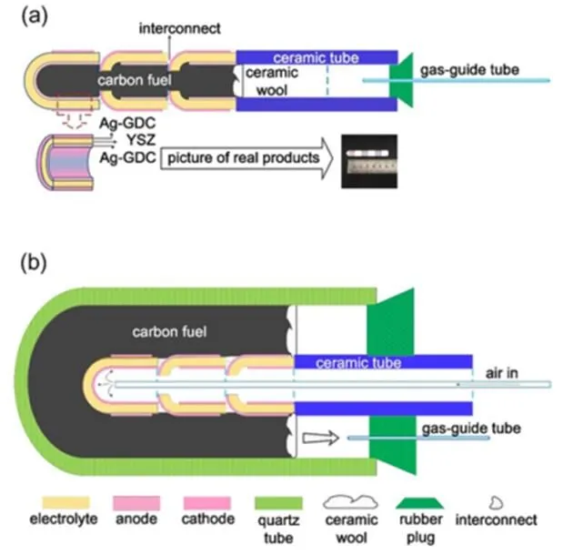
Fig.1 Schematic diagram of the 3-cell-stacks of DC-SOFC system with carbon fuel inside (a) and outside (b) of stack.
3 Results and discussion
3.1 Characteristics of the as prepared SOFCs
Fig.2 shows the section SEM image of an as prepared SOFC. It can be seen from Fig.2(a) that the thickness of the electrolyte is 195mm. Fig.2(b) shows that the electrolyte is relatively dense with closed pores while the electrode is porous with a thickness of ~18mm.
Fig.3 shows the output performances (a) and impedance spectra at open circuit voltage (b) of a typical single SOFC operated with humidified hydrogen (3% () H2O) as fuel and ambient air as oxidant. As can be seen from Fig.3(a), the open circuit voltage at 800°C is 1.06 V, very close to the theoretical value of 1.1 V, suggesting that the cell is well prepared and sealed. The power density of the cell at 800°C is about 240 mW∙cm−2. Fig.3(b) also shows an equivalent circuit of a SOFC. It consists of a resistor which represents ohmic resistanceoof the cell. Generally, the ohmic resistance of a SOFC is mainly contributed by the electrolyte, especially in the case of electrolyte-supported SOFCs. The equivalent circuit also consists of two units, each has a resistor and a capacitor connected in parallel. One unit, with resistancecand capacitancec, represents the polarization of the cathode. The other one, with resistanceaand capacitancea, represents the anode polarization process. It can be seen from Fig.3(b) that each impedance spectrum of the SOFC is a semi-circle like curve. The left intercept of the semicircle corresponds to the ohmic resistance,o, of the SOFC while the right one corresponds to the overall resistance, i.e., the sum of the ohmic resistance and the polarization resistance,p. The polarization resistance is the sum of the cathode polarization resistance and the anode polarization resistance, i.e.,p=c+a.The ohmic resistances for the SOFC operated at 700, 750, and 800°C are 1.15, 0.75, and 0.50W∙cm2, while the polarization resistances are 3.30, 0.85, and 0.25W∙cm2, respectively. At lower temperature, the polarization resistance dominates the energy loss while at higher temperature, the ohmic resistance is larger than the polarization resistance. As the SOFC is electrolyte-supported, the ohmic resistance should be mainly contributed by the electrolyte. As known from the SEM picture of the section of the SOFC, the thickness of the electrolyte is about 195mm. Therefore, the output performance of the DC-SOFC can be improved by reducing the thickness of the electrolyte.
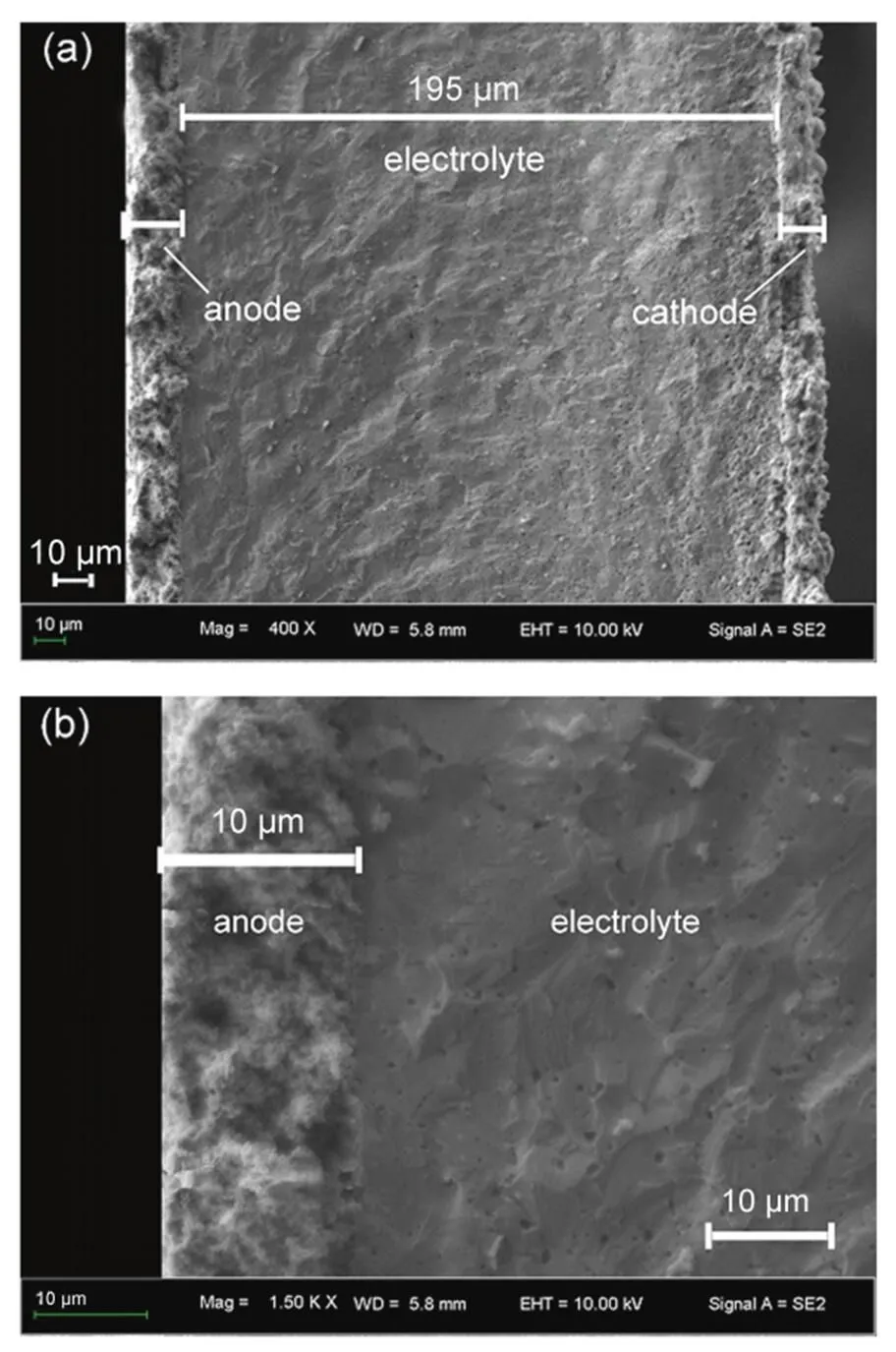
Fig.2 SEM images of cross section of the as prepared SOFC with YSZ electrolyte and Ag-GDC.

Fig.3 Output performances (a) and impedance spectra at open circuit voltage (b) of a single SOFC operated with humidified hydrogen (3% (φ) H2O at 25 °C) as fuel and ambient air as oxidant.
3.2 Performances of the DC-SOFC stacks
The output performances of the 3-cell-stacks of DC-SOFC operated at 800°C, with inside carbon fuel of 3 g and outside carbon fuel of 17 g, respectively, are shown in Fig.4. Both with a total effective area of 10.2 cm2, the stack with inside carbon gives a peak power of 3.2 W while that with outside carbon, 4.0 W, corresponding to specific areal power densities of 0.31 and 0.39 W∙cm−2, respectively. These values are even comparable to a 3-cell DC-SOFC stack with Ni-YSZ anode-supported configuration, with an electrolyte thickness of ~20mm and a total effective area of 5.2 cm2, which reveals a peak output power of 1.8 W at 800°C, corresponding to 0.35 W∙cm−24. As we know, the ohmic resistance of a SOFC is mainly from the electrolyte. The ohmic resistance of an anode-supported SOFC, with electrolyte thickness of 20mm, is obviously smaller than that of an electrolyte-supported, with electrolyte of 195mm. The total resistance of a SOFC or DC-SOFC is the sum of its ohmic resistance and polarization resistance. As the electrolyte-supported DC-SOFC stack, with Ag-GDC as electrode material, gives a power density comparable to that of the Ni-YSZ anode-supported one, the polarization resistance of Ag-GDC might be smaller than that of the conventional Ni-YSZ, when used as the anode of DC-SOFCs.
Note that the output power of the stack with outside carbon is higher than that with inside carbon. There are two possible reasons for this: 1. larger amount of carbon may provide more reaction sites for the reversed Boudouard reaction, thus sufficient CO may be produced for the electrochemical reactions at the anode; 2. flowing air is applied in testing the stack with outside carbon, which may reduce the concentration polarization of the cathode. To confirm which one is true, a single SOFC is tested, respectively with hydrogen fuel flowing through the interior and exterior of the cell, in the same flowing rate and at the same temperature. Similar to the situation of the DC-SOFC stacks, air is flowing through the cathode side for the cell with exterior fuel (the flow rate of air is 50 mL∙min−1) while ambient static air is used as the oxidant for the cell with interior fuel. The results shown in Fig.5 proved that the performances of the SOFC with hydrogen provided from inside and outside are similar, suggesting that the second reason is false. In other words, the higher performance of the stack with outside carbon is related to the larger amount of carbon. As we know, the electrochemical reaction which provides electrical power in a DC-SOFC is the oxidation of CO. One of the unique superiors of DC-SOFC is that the CO for the electrochemical oxidation is producedin the anode chamber. One CO2molecule, produced from the oxidation of one CO molecule, diffuses to the carbon fuel to perform the reversed Boudouard reaction, and will produce two CO molecules. Higher current means more CO2molecules are produced and this will stimulate more CO production. Generally, the production rate of CO2in a DC-SOFC is determined by the operating current while that of CO (produced from the reversed Boudouard reaction) depends on the reactivity of the carbon fuel. The number of the active sites of the carbon fuel is an important facts affecting the activity. Therefore, the stack with outside carbon, with larger amount of carbon, thus more active sites, gives higher performance than the stack with inside carbon.
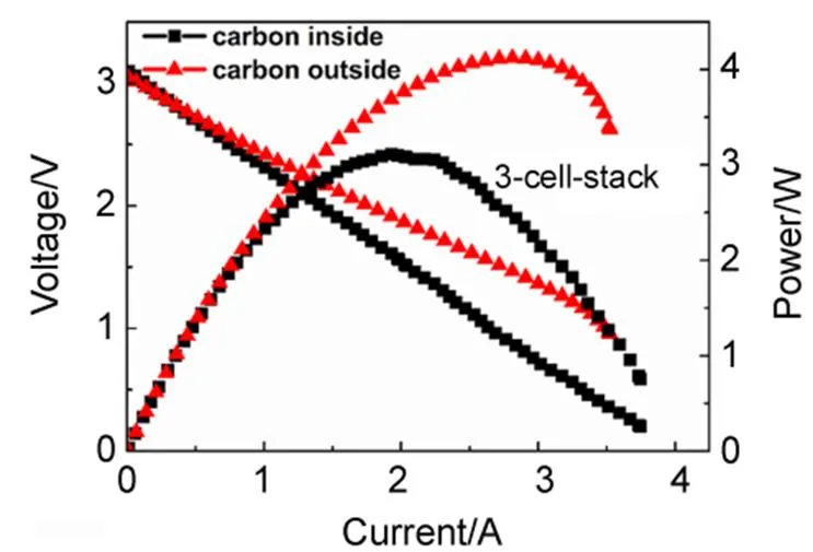
Fig.4 Performances of the tubular 3-cell-stacks of DC-SOFC operated at 800 °C, with carbon fuel inside (3 g) and outside (17 g) of the stack, respectively.
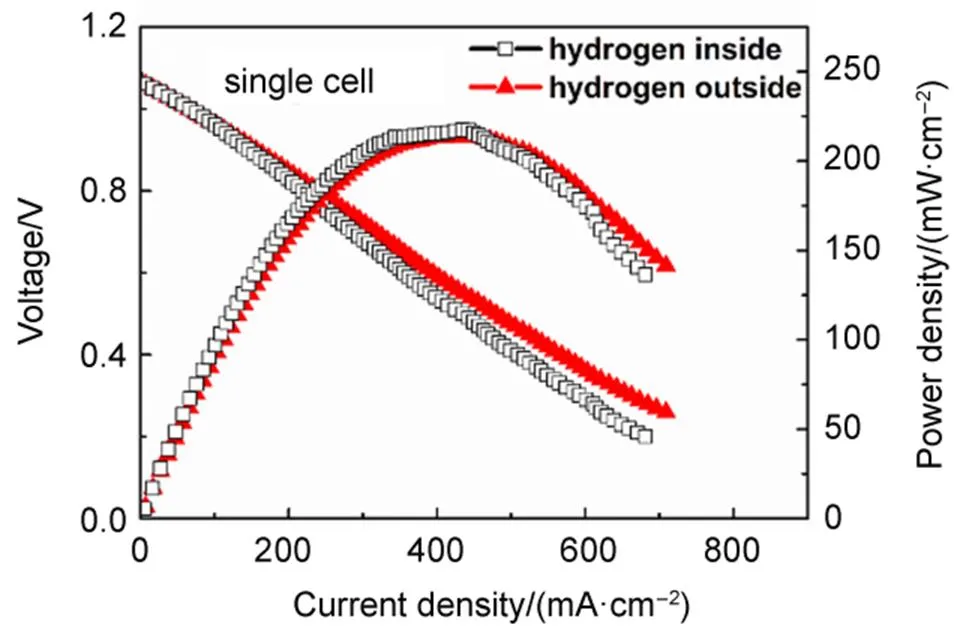
Fig.5 Comparison of performance of a single SOFC operated with hydrogen fuel inside (50 mL∙min−1) and outside (50 mL∙min−1) of the cell, respectively, at 800 °C.
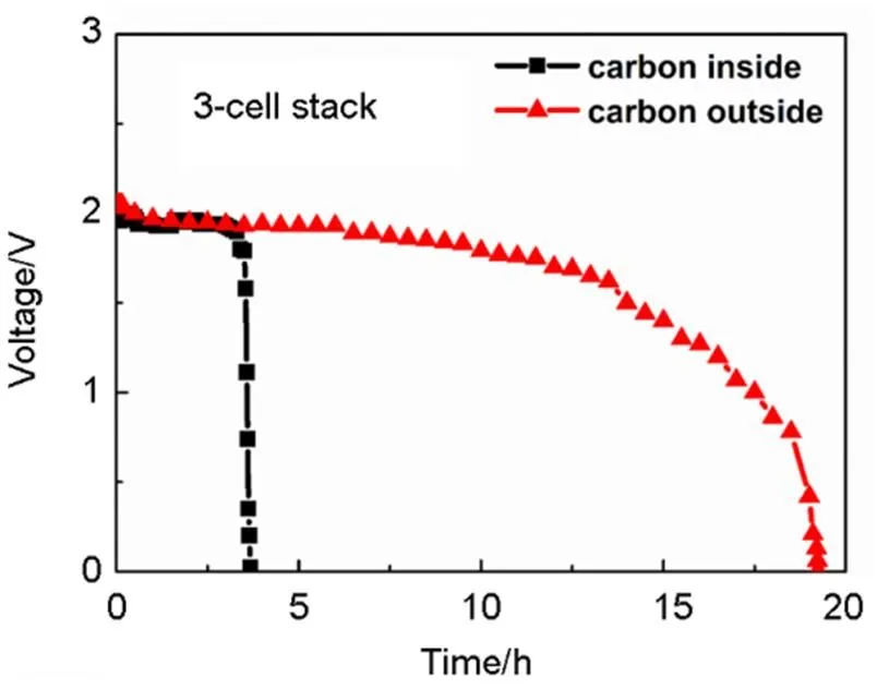
Fig.6 Discharging performance of the 3-cell-stack operated at 800 °C with 1 A current, respectively with carbon fuel in the interior and exterior.

Table 1 Selected data of the stacks
3.3 The discharging characteristics of the stacks
Fig.6 shows the discharging performances of the 3-cell-stacks, respectively with carbon fuel in the interior (i) and exterior (e), operated at a constant current of 1 A, at 800°C. Selected date of the stacks are listed in Table 1. The discharging time ofe(19 h) is obviously longer than that of Si(3.5 h). The ratio of the two discharging time (19/3.5»5.4) is very close to the ratio of the carbon amount loaded in the two stacks (17/3»5.6). This fact suggests that the discharging time of a DC-SOFC is nearly proportional to the amount of carbon fuel. The discharging capacities of the two stacks are 19 A∙h and 3.5 A∙h, respectively. Theoretically, the charge capacity of carbon (4 electron process) is 8.935 A∙h∙g−1. Therefore, the practical electrical conversion efficiency of the two 3-cell-stacks can be calculated as 37.5% and 39.2%, respectively. According to Fig.4, the energy capacity of the stack with interior carbon is 6.9 W∙h while that with exterior carbon is 31.6 W∙h, corresponding to mass energy densities of 2.30 W∙h∙g−1and 1.86 W∙h∙g−1, respectively. These values are significantly higher than the maximum energy density of current lithium ion batteries (~0.2 W∙h∙g−1). A high volumetric energy density is also very important for portable application. The tap density of the presented activated carbon is 0.56 g cm−3. Therefore, the volumetric energy density of the DC-SOFC stack with interior carbon is 1.29 W∙h∙cm−3, while that with exterior carbon is 1.04 W∙h∙cm−3. Besides, a DC-SOFC, or a carbon-air battery do not need charging, only refilling carbon into the cell can maintain its operation.
Note that the discharging curve for the stack with carbon inside drops rapidly at the end of discharging, while that with carbon outside drops gradually. This difference may be caused by the distance change between the anode and the carbon fuel. There has been research showing that the performance of a DC-SOFC is sensitive to the distance between the anode and the carbon fuel, as a longer time is needed for the diffusion of CO or CO230. For the stack with carbon inside, the amount of carbon is small and the distance between anode and carbon is close enough even at the end of discharging. However, for the stack with carbon outside, there are much more carbon in the anode chamber and it operates much longer time. As the carbon close to the anode is consumed with time, the distance between anode and carbon becomes larger enough to affect the output performance, which leads to the gradual decline, as shown in Fig.6.
4 Conclusion and prospective
A tubular DC-SOFC stack, or a carbon-air battery, with anode fabricated at the outside and carbon fuel loaded at the exterior of the stack, can provide an extremely large capacity. A segmented-in-series 3-cell-stack of DC-SOFC, with a total effective area of 10.2 cm2and with 17 g carbon loaded at the exterior, can well run for 19 h at a constant current of 1 A, at 800oC, giving a discharging capacity of 19 A∙h and an energy capacity of 30.6 W∙h. These values are significantly larger than those of a similar DC-SOFC stack but with carbon fuel loaded at the interior, in which the amount of carbon is limited by the cubage of the stack, only 3 g. The discharging time, discharging capacity, and energy capacity of the DC-SOFC stack are almost proportional to the amount of carbon integrated in the system. Taking carbon as the active material of DC-SOFC, its energy is tens of times larger than those of typical lithium ion batteries. In conclusion, the DC-SOFC may be developed for portable application in the near future and for large scale electrochemical conversion of coal, efficiently and cleanly, in a relatively far future.
(1) Cao, D.; Sun, Y.; Wang, G.2007,, 250.
doi: 10.1016/j.jpowsour.2007.02.034
(2) Nakagawa, N.; Ishida, M.1988,, 1181.
doi: 10.1021/ie00079a016
(3) Tang, Y. B.; Liu, J.2010,, 11188.
doi: 10.1016/j.ijhydene.2010.07.068
(4) Bai, Y. H.; Liu, Y.; Tang, Y. B.; Xie, Y. M.; Liu, J.2011,, 9189. doi:10.1016/j.ijhydene.2011.04.171
(5) Liu, J.; Liu, Y.; Tang, Y. B.; Bai, Y. H. A Direct Carbon Solid Oxide Fuel Cell Power System. CN Patent: ZL201110008698.8, 2013.
(6) Yang, B. B.; Ran, R.; Zhong, Y. J.; Su, C.; Moses O. T.; Shao, Z. P.2015,, 1. doi: 10.1002/ange.201411039
(7) Zhou, W.; Jiao, Y.; Li, S. D.; Shao, Z. P.. 2016,(2), 193. doi: 10.1002/celc.201500420
(8) Lee, A. C.; Mitchell, R. E.; Gür, T. M.2009,, 774. doi: 10.1016/j.jpowsour.2009.05.039
(9) Li, C.; Shi, Y. X.; Cai, N. S.2010,, 4660.
doi: 10.1016/j.jpowsour.2010.01.083
(10) Xu, X. Y.; Zhou, W.; Liang, F. C.; Zhu, Z. H.2013,, 402. doi: 10.1016/j.apenergy.2013.03.053
(11) Jayakumar, A.; Küngas, R.S. R.; Javadekar,A.; Buttrey, D. J.; Vohs, J. M.2011,, 4133.doi: 10.1039/C1EE01863A
(12) Xu, X. Y.; Zhou, W.; Zhu, Z. H.2013,(50), 17927. doi: 10.1021/ie403164c
(13) Zecevic, S.; Patton, E. M.; Parhami, P.2004,, 1983.
doi: 10.1016/j.carbon.2004.03.036
(14) Cooper, J. F.; Selman, R.2009,, 15.
doi: 10.1016/0950-4230 (95)00057-7
(15) Xie, Y. M.; Tang, Y. B.; Liu J.2013,, 121. doi: 10.1007/s10008-012-1866-5
(16) Rady, A.C.; Giddey, S.; Badwal, S. P.; Ladewig, B. P.; Bhattacharya, S.2012,, 1471.doi: 10.1021/ef201694y
(17) Gür ,T. M.2013,, 6179.doi: 10.1021/cr400072b
(18) Tang, Y. B.; Liu, J.; Sui, J.. 2009,, 1109.
doi: 10.1149/1.3205638
(19) Tang, Y. B.; Liu, J.2010,(5), 1191. [唐玉宝, 刘江. 物理化学学报, 2010,(5), 1191.]
doi: 10.3866/PKU.WHXB20100502
(20) Liu, R. Z.; Zhao, C. H.; Li, J. L.; Zeng, F. R.; Wang, S. R.2010,, 480. doi: 10.1016/j.jpowsour.2009.07.032
(21) Zhang, L.; Xiao, J.; Xie, Y. M.; Tang, Y. B.; Liu, J.; Liu, M. L.2014,, 272. doi: 10.1016/j.jallcom.2014.04.154
(22) Cai, W. Z.; Zhou, Q.; Xie, Y. M.; Liu, J.2015,, 887.
doi: 10.1016/j.fuel.2015.07.030
(23) Yu, F. Y.; Zhang, Y. P.; Yu, L.; Cai, W. Z.; Yuan, L. L.; Liu, J.; Liu, M. L.2016,, 9048.
doi: 10.1016/j.ijhydene.2016.04.063
(24) Xie, Y. M.; Cai, W. Z.; Xiao, J.; Tang, Y. B.; Liu, J.; Liu, M. L.2015,, 1. doi: 10.1016/j.jpowsour.2014.12.016
(25) Rady, A. C.; Giddey, S.; Kulkarni, A.; Badwal, S. P. S.; Bhattacharya, S.; Ladewig, B. P.2014,, 56.
doi: 10.1016/j.apenergy.2014.01.046
(26) Dudek, M.; Tomczyk, P.; Socha, R.; Hamaguchi, M.2014,, 12386. doi: 10.1016/j.ijhydene.2014.04.057
(27) Zhu, X. B.; Li, Y. Q.; Lü, Z.2016,, 5057. doi: 10.1016/j.ijhydene.2016.01.105
(28) Zhou, Q.; Cai, W. Z.; Zhang, Y. P.; Liu, J.; Yuan, L. L.; Yu, F. Y.; Wang, X. Q.; Liu, M. L.2016,, 250.
doi: 10.1016/j.biombioe.2016.05.036
(29) Cai, W. Z.; Zhou, Q.; Xie, Y. M.; Liu, J.; Long, G. H.; Cheng, S.; Liu, M. L.2016,, 1232.
doi: 10.1016/j.apenergy.2016.07.068
(30) Xu, H. R.; Chen, B.; Liu, J.; Ni, M.2016,, 353. doi: 10.1016/j.apenergy.2016.06.064
(31) Bai, Y. H.; Liu, J.; Gao, H. B.2009,, 554.
doi: 10.1016/j.jallcom.2009.01.089
(32) Liu, J.; Su, W. H.; Lü, Z.; Ji, Y.; Pei, L.; Liu, W.; He, T. M. A Rapid Sealing Method for Solid Oxide Fuel Cell Using Metal Conductive Adhesive. CN Patent: ZL 02133049.2. 2004.
可用作便携式电源的高性能直接碳固体氧化物燃料电池组
王晓强1刘 江1,*谢永敏1,2蔡位子1,3张亚鹏1周 倩1于方永1,4刘美林1,5
(1华南理工大学环境与能源学院新能源研究所,广州 510006;2江西理工大学冶金与化学学院,江西 赣州 3410003;3香港理工大学建筑与房地产学院,香港 999077;4山东理工大学化学工程学院,山东 淄博 255000;5美国佐治亚理工学院材料科学与工程系,亚特兰大 GA30332-0245,美国)
报道了一种直接碳固体氧化物燃料电池(DC-SOFC)电池组。该电池组由3个单节管式电池串接而成。为使电池组能够承载更多的碳,阳极制备在管状电池的外壁。此三节电池组直接以碳为燃料,空气中的氧气为氧化剂运行。该电池组的有效面积为10.2 cm2,以17 g负载5%()Fe的活性炭为燃料,800 °C下的功率为4.1 W。电池组以1 A的恒电流放电19 h,放电容量为19 A∙h,释放出31.6 W∙h的电能。这种高容量的DC-SOFC可开发成便携式电源加以应用。
固体氧化物燃料电池;碳燃料;锥管串接电池组;碳空气电池;便携式应用装置
O647
10.3866/PKU.WHXB201704181
February 17, 2017;
March 27, 2017;
April 18, 2017.
Corresponding author. Email: jiangliu@scut.edu.cn; Tel: +86-20-39381201.
The project was supported by the National Natural Science Foundation of China (21276097, 21567008, 21263005), Special Funds of Guangdong Province Public Research and Ability Construction, China (2014A010106008), Guangdong Innovative and Entrepreneurial Research Team Program, China (2014ZT05N200), and Program of Excellent Ph.D Thesis Authors of Guangdong Province, China.
国家自然科学基金(21276097, 21567008, 21263005), 广东省公共研究与能力建设专项资金(2014A010106008), 广东省创新企业团队项目(2014ZT05N200), 广东省优秀博士论文项目资助
