Design and evaluation of PID electronic control system for seed meters for maize precision planting
2017-11-01HeXiantaoDingYouqiangZhangDongxingYangLiCuiTaoWeiJiantaoLiuQuanweiYanBingxinZhaoDongyue
He Xiantao, Ding Youqiang, Zhang Dongxing,2, Yang Li,2, Cui Tao,2, Wei Jiantao, Liu Quanwei, Yan Bingxin, Zhao Dongyue
Design and evaluation of PID electronic control system for seed meters for maize precision planting
He Xiantao1, Ding Youqiang1, Zhang Dongxing1,2, Yang Li1,2※, Cui Tao1,2, Wei Jiantao3, Liu Quanwei1, Yan Bingxin1, Zhao Dongyue1
(1. College of Engineering, China Agricultural University, Beijing 100083, China; 2. Soil-Machine-Plant key laboratory of the Ministry of Agriculture of China, Beijing 100083, China; 3. CNH Industrial, Chicago 60527, USA)
A proportional-integral-derivative (PID) electronic control system for seed meters was developed to improve the planting quality and operation efficiency of conventional planters with ground wheel and chain driven system. A PID algorithm was used for controlling seed plate rotation speed. In addition, the PID controller incorporated integral separation of the integral term to increase the response time and reduce the occurrence of overshoot when the set point was far away from the current rotation rate. The final tuned PID parameter values wereK=16,K=0.05, andK=36. The response time, overshoot, and steady error for a seed plate rotation speed step response from 0 to 24 r/min were 0.4 s, 1.56%, and 0.75%, respectively. Experiment results showed that the Singulation index (SI) of seed meter could receive to 98.4%, and the Multiple index (UI) and Miss index (MI) were not more than 1% even at the highest planting speed of 12 km/h, which indicated that the seed meter with the developed control system and tuned PID parameters could obtain better planting quality and higher planting speed.
agricultural machinery; electronic control; performance; PID parameter tuning; integral separation
0 Introduction
Precision planters are used widely in China, and the performance of seed meter, which is a key component of precision planter, affects the uniformity of seed distribution directly[1]. However, conventional precision planters with ground wheels and chains driven system bring poor planting quality due to slippage between wheel and ground, and chain instability during the process[2]. Adopting electric motor to replace conventional mechanical driving system to drive seed meters is one of methods to solve the problems.
The agricultural machinery companies in the world, e.g. John Deere[3]and Horsch[4], have developed their characteristic driving seed meters for precision planter by using electric motors, and the high-technology agricultural machinery companies, e.g. Precision Planting[5]and Ag Leader[6], have also developed corresponding control system for precision planters equipped with electric-driven seed meters in recently years. The planters with technology above significantly improve the planting speed to 15 km/h and singulation to about 98%, but their prices are very high. In addition, Chaney et al.[7]designed a kind of electronic control system for a sugarcane planter. He et al.[8]developed a type of seed meter based on electromagnetic vibrating mode, and also designed its PLC controller. Tang et al.[9]designed a driving system for seed meters to control the speed of seed plate based on the planting speed. Zhai et al.[10-11]developed an automated driving system of seed metering according to sensor signal. But these researches are at testing stage and not applied in the market.
To solve issues above, this study developed a PID electronic control system for seed meters and conducted experiments to test the performance of the control system in the lab.
1 Material and methods
1.1 Components of the electronic control system
The system consisted of five components: control box, touch screen display (MT4414T, Kinco Automation company, China), incremental encoder (TRD-2T500BF, Koyo Electrical Company, Japan), seed plate driving motor (57BL55S06, Times Brilliant Electrical Company, China), seed meter, as in Fig. 1.

Fig.1 Components of electronic control system
A twelve volt power supply provides power for the entire control system. The seed meter adopted in this study was an air-pressure precision corn meter developed by Shi et al.[12-13], which was modified to be driven by seed plate driving motor. The motors are DC brushless motors, and each motor’s back is embedded by three Hall-effect sensors to measure the positions of the rotors and realize current switching for the rotors electronically, which eliminates brush maintenance of DC brush motor[14-16]. In the meantime, the Hall-effect sensors were used by the study to measure the motor rotation speed in real time for achieving closed-loop control[17]. The planting speed was measured by an incremental encoder that was mounted on the shaft of a ground wheel.
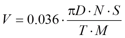
Whereis the planting speed, km/h;is diameter of the ground wheel, cm;is the sample period, s;is the number of pulses received within the period of;is the wheel slip ratio, %;is resolution of the encoder, pulses/r.
A touch screen display as interface of data input/output used to enter planting parameters such as number of seed holes per disk seed spacing,and, and also display planting speed and rotation speed of seed plate. The touch screen display was communicated with the controller by RS485. The controller is the core of the system, which was designed to receive input data from incremental encoder and touch screen display and output a signal pulse with a certain frequency and duty cycle to adjust seed plate rotation speed for achieving desired seed spacing as planned. The seed plate rotation speed is calculated as
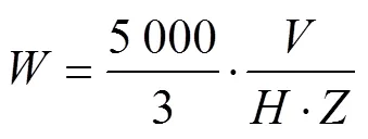
Whereis the seed plate rotation speed, r/min;is the number of seed holes per disk;is the seed spacing, cm.
1.2 PID control of seed plate rotation speed
As PID control is a simple algorithm with high reliability, and commonly used in various control systems[18-21], a closed-loop PID is used in this study to control the seed plate rotation speed for improving the seed plate’s dynamic performance. The PID control principle was illustrated in Fig.2.

Fig.2 Schematic diagram of PID control principle
The controller computes the error between the target values and actual values of seed plate rotation speed at time t, then control the motor speed by adjusting the signal duty cycle. A basic PID controller in continuous time[22-23]is described by

WhereP() is the signal duty cycle;() is the error between the target values ((), r/min) and actual values ((), r/min) of seed plate rotation speed at time t, r/min;K, KandKare the proportional, integral, and differential gain constant, respectively. Equation (3) is discretized as follows for reducing computational cost[22-23].
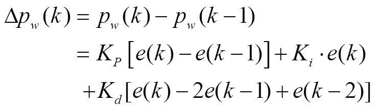
Here,(),p() (r/min) are the discrete error and control signal’s duty cycle, respectively;is sampling points.
1.3 Setting PID parameters via step response analysis
The present study employed a trial-and-error method to estimate the PID parameters by laboratory experiments. Given a step response in, the step response curve was plotted, and the impact of each PID parameter was analyzed in turn through trial and error to obtain a response curve that provided a rapid response time and a small stable error within a small overshoot. The overshoot was set here to be within 2%, and PID parameter selection providing the optimal performance of the control response was based on an appropriate tradeoff between the minimum response time and the minimum stable error.
The laboratory setup employed for tuning is illustrated in Fig.3. The encoder (1 in Fig.3) was mounted on the shaft of a meter that measures the actual value ofin real time, and the rotation speed signal was sent to a data acquisition card (2 in Fig. 3; National Instrument USB-6009). LabView software was installed on a PC (3 in Fig. 3) to read the signal from the data acquisition card, calculate the meter’s rotation speed, and then display it to obtain the step response of. Planting parameters are entered through the touch screen display with=25 cm and=9 km/h, resulting a target value of in=24 r/min, thus, registering a step response from 0 to 24 r/min. Zhengdan 958 maize hybrid seeds were employed in the calibration, and the air pressure was set at 3.0 kPa. The encoder’s resolution was 2 500 pulses/r, and the data acquisition rate was 10 Hz.
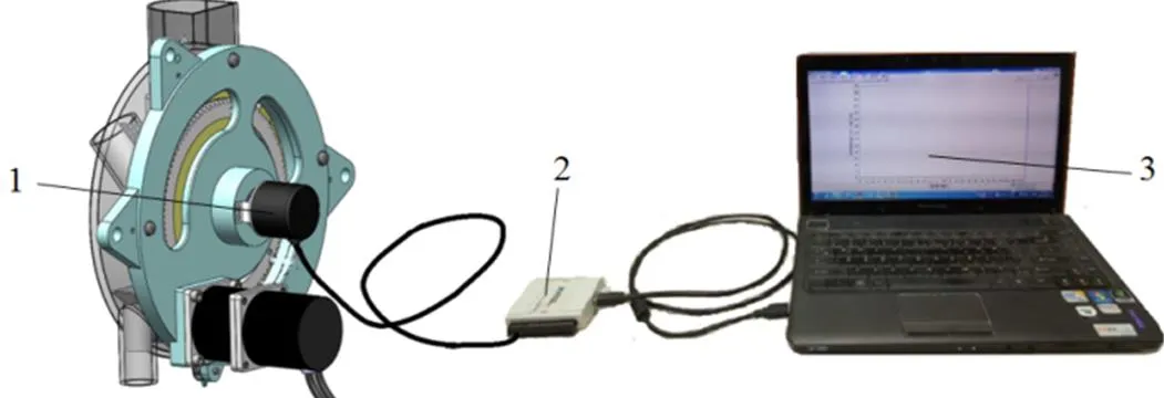
1.Incremental encoder 2.Data acquisition card 3.PC interface for LabView software
Fig.3. Test setup employed for tuning PID parameters
1.3.1 Setting the proportional gain constant (K)
To determineK, we considered only proportional control in the trial and error experiments (i.e.,K=K=0). The proportional term produces an output value at sampling pointthat is proportional to(). The proportional response can be adjusted by multiplying() byK. A high proportional gain results in a large change in the output for a given change in() (i.e.,()−(−1)), and an overly high gain can make the system unstable. In the tuning process shown in Fig. 4, settingK=5 responded too slow, andKwas then incrementally increased to 10, 15 and 20. The response plot forK=15 exhibits the beginning of overshoot, which is greatly increased whenK=20. Therefore,Kshould be between 15 and 20. Further fine tuning obtained an optimal value ofK=16, which, shown in Table 1, provides minimum values for both the response time and stable error.
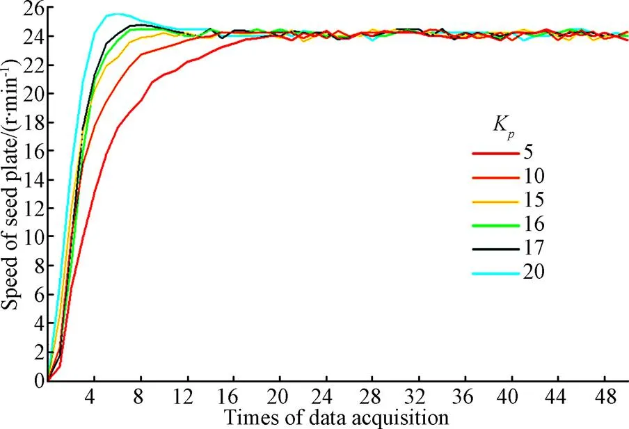
Note: Kp is the proportional gain constant. Same as below.
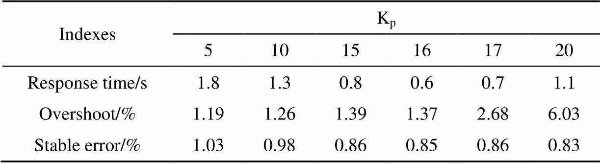
Table 1 Step response results for tuning Kp (proportional controller only, i.e., Ki=Kd=0)
Note:Kis the integral gain constant;Kis the differential gain constant, Same as below.
1.3.2 Setting the integral gain constant (K)
To determineK, we considered only proportional- integral control in the trial and error experiments (i.e.,K= 0), and the previously optimized valueK=16 is employed as a constant. The integral term can eliminate the residual steady-state error that occurs with a pure proportional controller. However, it may slow down the system response and cause additional overshoot. Fig.5 presents the step response curves obtained forKvalues of 0.01 and 0.1 (red and green curves, respectively), where we observe that integral accumulation for even a small value ofK=0.01 delays the response time and increases system overshoot due to the initially large overshoot of 1.37% associated with proportional control alone. While the overshoot caused by the integral term would be reduced by decreasingKappropriately, this would also further increase the response time. Therefore, we retain a constantK, and employ integral separation[24-27]to reduce the overshoot and slow response caused by the integral term. This method employs a switching variableXto omit the integral term when() is large, and to include the integral term when() is small. The switching variable is defined as follows[28-29].

The overall PID equation after introducingX[28-29]is given as

Employing only the first 2 terms of Equation 6, a comparison between the results with and without integral separation given in Fig.5 showed that the added delay is eliminated and no overshoot occurs forK=0.01. However,K=0.1 induces a minor degree of overshoot, indicating thatKshould be between 0.01 and 0.1. The tuning results are listed in Table 2. Fine tuning of the integral term yields an optimal valueK=0.05. Here, compared withK=0.01, the steady error is reduced to 32.5% while the response time is increased to only 16.7%, indicating that the performance withK=0.05 is better. Compared with proportional control only, the steady error is reduced to 0.56% (i.e., a 34% reduction).
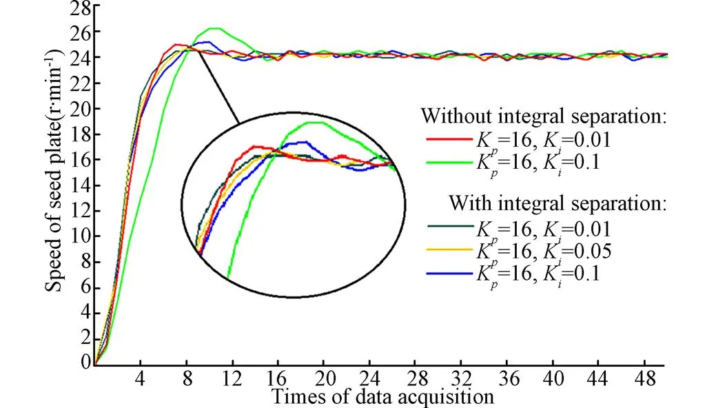
Fig.5 Step response curves from Ki tuning

Table 2 Step response results with integral-separation method (proportional-integral controller only, i.e., Kd=0)
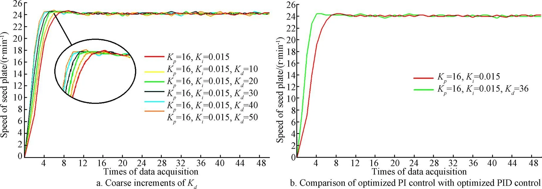
1.3.3 Setting the differential gain constant (K)
The derivative of the error predicts system behavior, and thus improves the settling time and stability of the system, but it is sensitive to system noise, and can cause oscillation. Holding the other values constant atK=16 andK=0.05 during tuning,Kis initially selected as 10, 20, 30, 40, and 50, and the response curves obtained are shown in Fig.6a. The response times tend to decrease over the initial range forK, achieving a minimum value at 40 and 50. However, consideration of the tuning results listed in Table 3 indicates that the steady error also increases over the initial range forK, indicating thatKshould be less than 40. Through fine tuning, the optimal value ofK=36 was determined. Here, compared withK=20, the response time is reduced by 20% while the steady error is increased by only 17.2%, indicating a better response performance withK=36. The final parameters obtained by tuning areK=16,K=0.05, andK=36. The response time, overshoot, and steady error obtained with these parameters are 0.4 s, 1.56%, and 0.75%, respectively. Compared with the PI controller, the response time is reduced by 0.3 s, as shown in Fig.6b.
Note: Kd is gain constant and same as below.

Table 3 Step response results for tuning Kd (full PID controller)
1.3.4 System step response under different planting speeds
The proposed control system is mainly employed for high speed planting. To validate the performance at high speed, step response testing for values ofof 8 km/h to 14 km/h was conducted with=25 cm, and the results are shown in Fig.7.

Fig.7 Step response curves under different planting speeds
The target values ofassociated with each value ofare given in the chart legend. At 14 km/h, the step response exhibits instability and the actual value of(i.e., 35 r/min) did not attain the target value of 37.33 r/min . This may have caused by an inability of the motor to reach the target speed at the twelve volt power supply, which was applied based on the power supply voltage of the tractor. Adopting a power converter to transfer twelve volt to twenty-four volt is a way to increase speed of seed plate, but this raises the energy consumption and cost of the control system. But forless than 14 km/h, the step response was very stable. Therefore, the maximum working speed of the control system can reach at 13 km/h, which is much too high than the working speeds of conventional planters.
2 Results and discussion
2.1 The performance of the control system
The performance of the proposed control system was tested in laboratory with three replications. Zhengdan 958 maize hybrid seeds were employed, and the air pressure was set at 3.0 kPa. Planting parameters were entered through the touch screen display with=25 cm,=50 cm and three planting speeds (6, 9 and 12 km/h, respectively).Using a camera to record planting condition, as in Fig.8.
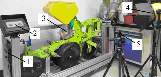
1.Control box 2.Touch screen display 3.Seed meter 4.Light source 5.Camera
Basing on China National Standard of Test Methods of Single Seed Driller (GB/T 6973-2005)[30], the performance indexes is calculated as follows.


Where1is the number of singles,2is the number of multiples,3is the number of skips, and′ is the number of theoretical planting seeds. SI is singulation index of seed meter; UI is multiple index of seed meter; MI is miss index of seed meter.
The results of experiment is shown in Table 4 and Fig.9.
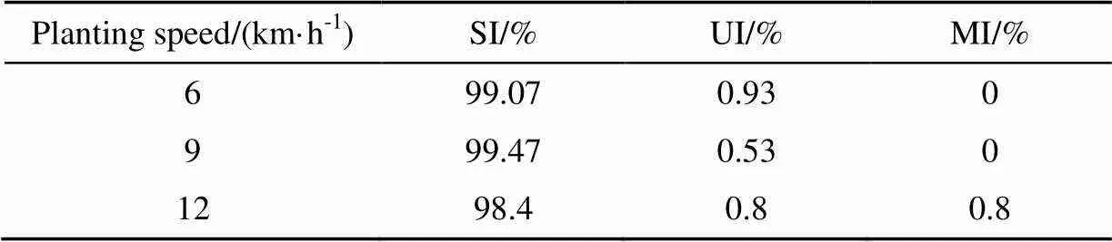
Table 4 Results of experiment
Note: SI is singulation index of seed meter; UI is multiple index of seed meter; MI is miss index of seed meter. The same below.
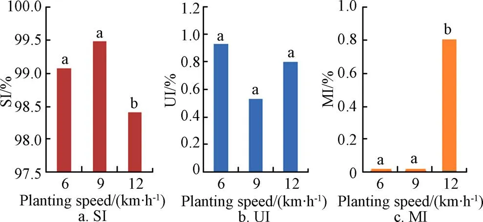
Note: Columns labeled with same letters are not significantly different.
As shown in the Table 4, with the increase of the planting speed, the SI, UI and MI didn’t change significantly. The data also showed that SI increased at first and then decreased with the planting speed increasing, and the best value was 99.47% at speed of 9 km/h. UI decreased at first and then increased with the speed increasing, and the worst value was 0.93% at speed of 6 km/h. MI were both zero at speed of 6, 9 km/h, but the value reached 0.8% at the speed of 12 km/h. Analyses above showed that UI was the determinant factor lead to SI decreasing when at low planting speed (6, 9 km/h), then MI became determinant instead of UI at the high planting speed (12 km/h). The best planting performance was got at speed of 9 km/h with SI of 99.47%, UI of 0.53% and MI of 0%. However, even at the highest planting speed of 12 km/h, the SI of seed meter can also be 98.4%, meanwhile the UI and MI were not more than 1%, which are far better than China National Standard[31]. Further analysis shown in Fig. 9 indicates that, when planting speed increased from 6 km/h to 9 km/h, the SI, UI, and MI changed only moderately. However when planting speed changed from 9 km/h to 12 km/h, the SI and MI changed appreciably. This change was possibly caused by the requirement of higher air pressure at higher planting speed. Results indicate that the seed meter with the developed control system and tuned PID parameters can obtain better planting quality and higher planting speed.
2.2 The cost and market expectation of the control system
Most of the components used in the control system are locally manufactured in China, and their costs are listed in the Table 5. The table indicates that, the cost of expanding one planting row that includes a seed plate driving motor and a seed meter is $321, and the control system has a higher performance-price ratio with the number of planting row increasing. The total cost of the control system for a four-row planter is $1800, which is considerably less than similar systems from abroad (for example, the cost of the controller alone from Precision Planting LLC is greater than $5000 in the Chinese market), making the system accessible to precision planters in developing countries and be largely used in the market.
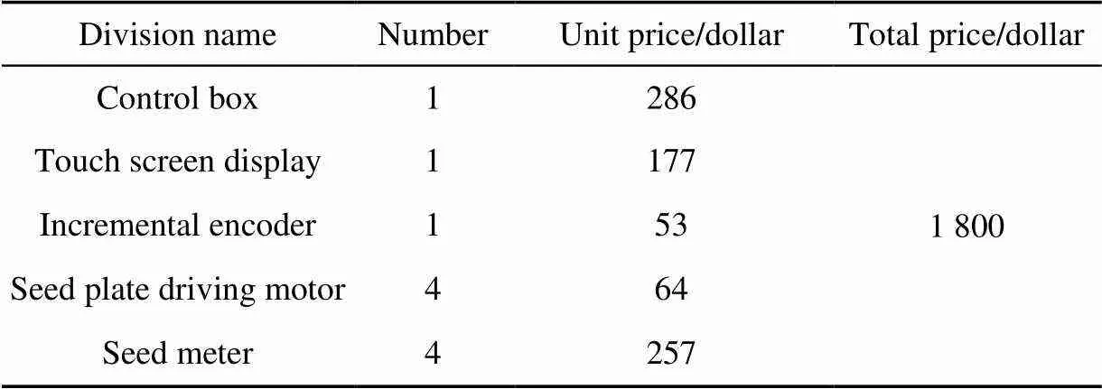
Table 5 Cost of control system for a four-row planter
3 Conclusions
A PID electronic control system for seed meters was designed and evaluated in this study. Conclusions of this research were as follows.
1) Using integral separation in the PID control algorithm reduced the issues of overshoot and delayed response time associated with the integral component under conditions when the error is large. After tuning, the final PID parameters obtained wereK=16,K=0.05, andK=36. Under a step response infrom 0 to 24 r/min, the response time, overshoot, and steady error were 0.4 s, 1.56%, 0.75%, respectively.
2) The experiment data showed that the SI of seed meter can be 98.4%, meanwhile the UI and MI are not more than 1% even at the highest planting speed of 12 km/h, which indicate that the seed meter with the developed control system and tuned PID parameters can obtain better planting quality and higher planting speed.
3) Most of the components used in the electronic control system are locally manufactured in China, which is considerably less expensive than the similar systems abroad, making the system accessible to precision planters in developing countries.
[1] Zhang Junchang, Yan Xiaoli, Xue Shaoping, et al. Design of no-tillage maize planter with straw smashing and fertilizing[J]. Transactions of the Chinese Society for Agricultural Machinery, 2012, 43(12): 51-55.
[2] Saadat K, Mohammad J E, Mohammad M M. Design, development and evaluation of a mechatronic transmission system to improve the performance of a conventional row crop planter[J]. International journal of Agronomy and Plant Production, 2013, 4(3): 480-487.
[3] Deere & Company (brand name John Deere). John deere Exact Emerge row unit[EB/OL]. [2016-08-05]. https://www. deere.com/en/planting-equipment/row-units/exactemerge-row- unit/
[4] Horsch Maschinen GmbH. Maestro CC Technical Data [EB/OL]. [2016-08-17]. http://www.horsch.com/produkte/ saemaschinen/einzelkornsaemaschinen/maestro/maestro-cc/
[5] Precision Planting LLC. Precision Planting vSet Select meter[EB/OL].[2016-09-21]. http://www.precisionplanting.com/#products/vset_select/.
[6] Ag Leader Technology. Ag Leader SureDrive[EB/OL]. [2016-09-10]. http://www.agleader.com/products/seedcommand/sure-drives/.
[7] Chaney P P, Parish R L, Sistler F E. Automatic control system for a sugarcane planter[J]. Applied Engineering in Agriculture, 1986, 2(2): 51-54.
[8] He Peixiang, Yang Mingjin, Chen Zhonghui. Study on photoelectric controlled precision seeder[J]. Transactions of the Chinese Society for Agricultural Machinery, 2003, 34(1): 47-49.
[9] Tang Yaohua, Zhang Jinguo. Seed sowing driving system based on non-contact speed measuring[J]. Agri Mech Research, 2009(3): 21-23.
[10] Zhai Jianbo, Gao Haizhou, Zheng Xiaolong, et al. Research on automatical seed metering drive system based on sensor technology[J]. Hubei Agricultural Sciences, 2011, 50(17): 3619-3621.
[11] Zhai Jianbo, Xia Junfang, Zhou Yong, et al. Design and experimental study of the control system for precision seed-metering device[J]. International Journal of Agricultural & Biological Engineering, 2014, 7(3): 13-18.
[12] Shi Song, Zhang Dongxing, Yang Li, et al. Design and experiment of pneumatic maize precision seed-metering device with combined holes[J]. Transactions of the Chinese Society of Agricultural Engineering (Transactions of the CSAE), 2014, 30(5): 10-18.
[13] Shi Song, Zhang Dongxing, Yang Li, et al. Simulation and verification of seed-filling performance ofpneumatic- combined holes maize precision seed-metering device based on EDEM[J]. Transactions of the Chinese Society of Agricultural Engineering (Transactions of the CSAE), 2015, 31(3): 62-69.
[14] Xun Qian, Wu Yong, Wang Peiliang, et al. Starting control strategy of brushless DC motor based on Hall rotor position sensor[J]. China Measurement & Test, 2016, 42(8): 118-122.
[15] Chen Yonghua. Application of Hall Effect in the control of brushless DC motor [J]. Experiment Science and Technology, 2011, 9(2): 34-36.
[16] Zhang Qingchao, Ma Ruiqing, Zhang Zhen, et al. Electromagnetic torque observation of brushless DC motor based on hall position signals[J]. Transactions of China Electrotechnical Society, 2015, 30(10): 187-195.
[17] Guo Wei, Wang Mingming. A modified speed measurement method using frequency multiplication to the hall signal of BLDC motor[J]. Micromotors, 2012, 45(1): 74-84.
[18] Knospe C. PID control[J]. IEEE Control Systems Magazine, 2006, 26(1): 30-31.
[19] Sigurd S. Simple analytic rules for model reduction and PID controller tuning[J]. Journal of Process Control, 2003, 13(4): 291-309.
[20] Bucz Š, Kozáková A, Vesely V. Easy Tuning of pid controllers for specified performance[J]. IFAC Proceedings Volumes, 2012, 45(3): 733-738.
[21] Yun Li, Ang K H, Chong G. PID control system analysis and design[J]. Control Systems IEEE, 2006, 26(1): 32-41.
[22] Ang K H, Chong G, Li Y. PID control system analysis, design, and technology[J]. IEEE transactions on control systems technology, 2005, 13(4): 559-76.
[23] Al-Mashakbeh A S. Proportional integral and derivative control of brushless dc motor[J]. European Journal of Scientific Research, 2009, 35(2): 198-203.
[24] Jiang Weirong, Huang Haibo, Lan Jianping. Simulation and design of integral separation fuzzy control system for brushless DC motor[C]//International Conference on Computational and Information Sciences, 2013: 1194-1197.
[25] Theorin A, Hägglund T. Derivative backoff: The other saturation problem for PID controllers[J]. Journal of Process Control, 2015, 33: 155-160.
[26] Guo Xuyang, Qi Xiaohui, Tian Lizhuang. AC servo system based on integral partition PID control[J]. Modern Electronics Technique, 2007, (19): 163-164.
[27] Wang Xiaodong. A kind of integration separation pid controller's designing[J]. Shanxi Science and Technology, 2006(6): 104-106.
[28] Li Ge, Jia Yuanwu, Zhang Hua, et al. Application of integral-separation PID control algorithm in PLC-based tension control system[J]. Journal of Textile Research, 2008, 29(8): 109-112.
[29] Ye Shuliang, Wang Keqi. The design of digital PID control with separated integral for an ultra-precision positioning system[J]. Techniques of Automation and Applications, 2003, 22(10): 65-67.
[30] Standardization Administration of the People’s Republic of China. Testing Methods of Single Seed Drills (precision drills): GB/T 6973-2005[S]. Beijing: Standards Press of China, 2005.
[31] Standardization Administration of the People’s Republic of China. Specifications for single seed drills (precision drills): JB/T 10293-2001[S]. Beijing: Standards Press of China, 2001.
玉米精量排种器电驱PID控制系统设计与性能评价
和贤桃1,丁友强1,张东兴1,2,杨 丽1,2※,崔 涛1,2,魏剑涛3,刘全威1,颜丙新1,赵东岳1
(1. 中国农业大学工学院,北京 100083; 2. 农业部土壤-机器-植物系统技术重点实验室,北京 100083;3. 凯斯纽荷兰公司,芝加哥 60527)
本文研究了一种基于PID的排种器电驱控制系统,取消了播种机采用地轮和链条驱动的方式,提高了播种机的播种质量和作业速度。采用PID算法控制排种盘转速,在目标转速与当前转速差异较大时,加入PID积分分离算法,以减少转速的超调量。通过整定后的PID参数为:K= 16、K= 0.05、K= 36,在其排种盘转速范围为0~24 r/min时,响应时间、超调量、稳态误差分别为0.4秒,1.56%和0.75%。试验结果表明,在12 km/h的高速播种作业条件下,采用该电驱控制系统的排种器排种单粒率仍然可达到98.4%,其重播率和漏播率小于1%。采用本文研究的基于PID算法的排种控制系统可以获得良好的排种质量和更高的排种速度,使排种器更适宜高速精量播种。
农业机械;电驱控制;性能;PID整定;积分分离
10.11975/j.issn.1002-6819.2017.17.004
TP273
A
1002-6819(2017)-17-0028-06
2017-04-07
2017-08-02
the National Key Research and Development Program of China (No.2017YFD0700703); the National Natural Science Foundation of China(51575515); China Agriculture Research System (CARS-02).
He Xiantao, Doctor, major research direction is intelligent agricultural equipment. Beijing, China Agricultural University, 100083. Email: hxt@cau.edu.cn
Yang Li, Professor, Doctoral supervisor, major research direction is modern agricultural machinery and intelligent agricultural equipment. Beijing, China Agricultural University, 100083. Email: yangli@cau.edu.cn