垂直自由层倾斜极化层自旋阀结构中的磁矩翻转和进动∗
2017-08-07王日兴叶华王丽娟敖章洪
王日兴 叶华 王丽娟 敖章洪
1)(湖南文理学院洞庭湖生态经济区建设与发展省级协同创新中心,常德 415000)
2)(湖南文理学院电气与信息工程学院,常德 415000)
垂直自由层倾斜极化层自旋阀结构中的磁矩翻转和进动∗
王日兴1)2)†叶华2)王丽娟2)敖章洪2)
1)(湖南文理学院洞庭湖生态经济区建设与发展省级协同创新中心,常德 415000)
2)(湖南文理学院电气与信息工程学院,常德 415000)
(2017年2月20日收到;2017年3月18日收到修改稿)
在理论上研究了垂直自由层和倾斜极化层自旋阀结构中自旋转移矩驱动的磁矩翻转和进动.通过线性展开包括自旋转移矩项的Landau-Lifshitz-Gilbert方程并使用稳定性分析方法,得到了包括准平行稳定态、准反平行稳定态、伸出膜面进动态以及双稳态的磁性状态相图.发现通过调节电流密度和外磁场的大小可以实现磁矩从稳定态到进动态之间的转化以及在两个稳定态之间的翻转.翻转电流随外磁场的增加而增加,并且受自旋极化方向的影响.当自旋极化方向和自由层易磁化轴方向平行时,翻转电流最小;当自旋极化方向和自由层易磁化轴方向垂直时,翻转电流最大.通过数值求解微分方程,给出了不同磁性状态磁矩随时间的演化轨迹并验证了相图的正确性.
磁矩翻转,自旋转移矩,稳定性分析
1 引言
由自旋极化电流产生的自旋转移效应[1,2]因其在信息处理和和微波激发中广阔的应用前景,被认为是自旋电子学发展史上一里程碑式的发现.如果沿垂直于具有极化层/隔离层/自由层的自旋阀结构施加电流,当电子从极化层流向自由层时,首先被极化为与极化层磁矩方向相同的自旋极化电流.此自旋极化电流经过隔离层进入自由层时,局域磁矩和传导电子之间发生相互作用,由于角动量守恒,自旋极化电流会给自由层磁矩施加自旋转移矩,从而驱动自由层磁矩产生进动[3],甚至发生翻转[4−7].
由于通过改变直流电流密度的大小可以方便地改变微波频率,因而自旋转移矩驱动磁矩产生进动的行为可以应用在无线通信领域,在芯片上做成频率为GHz且频率可调的微波源.同时,由于电流操控磁性状态可以更好地实现局域控制,在器件的应用中可以大大减少器件的复杂性,有利于器件在芯片上的集成,因而自旋转移矩驱动磁矩翻转在电流直接操控的磁随机存储器方面有着巨大的应用前景,预计将会给磁随机存储器带来一种全新的数据写入方式[8].
目前,对自旋阀结构中自旋转移矩驱动磁化动力学的研究大部分都集中在具有平行磁各向异性和垂直磁各向异性的自旋阀结构.与平行磁各向异性的自旋阀结构相比较,垂直磁各向异性的自旋阀结构具有更大的磁电阻率、更好的热稳定性、并且能够诱导更快速的磁矩翻转[9].除了平行磁各向异性和垂直磁各向异性的自旋阀结构以外,研究表明倾斜极化的自旋阀结构[10−17]在保持更高的热稳定条件下,更有利于高密度的数据存储[10−12].另外,倾斜极化的自旋阀结构还为操控自旋阀结构中的磁动力学提供了新的途径[13−15].在实验上,倾斜极化的自旋阀结构也已经得到了实现[10,11].
本文对自由层具有垂直磁各向异性的倾斜极化自旋阀结构中自旋转移矩驱动的磁矩翻转和进动进行了理论研究. 通过线性展开包含自旋转移矩项的基于宏观磁矩的Landau-Lifshitz-Gilbert(LLG)方程,使用线性稳定性分析方法[14,15,17−21],获得了垂直自由层倾斜极化层自旋阀结构的磁性状态相图.相图中包括多种不同的磁性状态.通过数值求解微分方程,给出不同磁性状态磁矩随时间的演化轨迹,证明了相图的正确性.
2 理论模型和线性化展开
图1为本文所研究的理论模型和坐标系,它是一个由两铁磁层中间被非磁金属层隔开的多层膜结构,定义x-z平面为多层膜的膜面.上面较厚的铁磁层为极化层,它的磁化方向被固定.下面较薄的铁磁层为自由层,其易磁化轴垂直于膜面方向,即沿y轴方向.自由层磁矩均匀分布且不随空间坐标变化,因此可以忽略交换作用,近似为单磁畴结构[14,15,22−24].当垂直于自旋阀结构施加电流时,局域磁矩和自旋转移矩发生相互作用.自由层磁矩的磁动力学行为可以用一个包含自旋转移矩项的LLG方程来描述[1,2]:
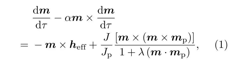

图1 理论模型和坐标系Fig.1.Theoretical mode and coordinate system.
式中,m和mp分别为自由层和极化层磁矩的单位矢量,mp=(px,py,pz)=(sinθpcosϕp,sinθpsinϕp,cosθp), θp和ϕp分别为极化层磁矩的极角和方位角;τ=4πγMst为重新定义的时间变量,其中,γ为旋磁比,Ms为自由层的饱和磁化强度;α为吉尔伯特阻尼常量;有效场heff=(κmy+hy)ey,包括各向异性场、退磁场和外磁场,其中,有效的各向异性场κ=hk−1,hk=Hk/(4πMs),hy=Hy/(4πMs),Hk和Hy分别为沿y轴方向的各向异性场和外磁场,ey为沿y轴方向的单位向量;J为电流密度,定义电流从极化层流向自由层时J取正值,从自由层流向极化层时J取负值;自旋矩项对应的系数Jp=[3(1+P)3/(2P3/2)− 8]4πdeM2s/,其中,P为自旋极化率,d为自由层的厚度,e为基本电荷,为普朗克常量;λ为描述自由层和极化层磁矩之间的夹角对自旋转移矩影响的无量纲的参数,其表达式为λ=(1+P)3/[3(1+P)3−16P3/2].
在球坐标系中将方程(1)展开,可以得到微分方程组

式中,θ和ϕ分别为自由层磁矩在球坐标系中的极角和方位角;pr,pθ,pϕ为极化层磁矩在球坐标系中的组分,其表达式为

在没有施加电流时,从(1)式中可以看出系统的两个平衡点分别为m=ey和m=−ey,对应球坐标系中的坐标为 (π/2,π/2)和 (π/2,3π/2). 当垂直于自旋阀结构施加电流时,自由层磁矩将到达一个新的平衡位置(θ0,ϕ0).在微小扰动的作用下,磁矩将绕此新平衡位置做微小振动,设磁矩对新平衡位置的偏离分别为δθ和 δϕ.因此,可以令θ= θ0+δθ,ϕ= ϕ0+δϕ.将其代入方程(2),保留δθ和 δϕ的线性项,可以得到关于新平衡位置(θ0,ϕ0)的方程组

以及关于δθ和δϕ的线性微分方程组

3 结果与讨论
假设磁矩做周期性振动,令δθ= ∆θeiωt和δϕ=∆ϕeiωt,其中∆θ和 ∆ϕ为振幅.将其代入方程组(4),可得


根据线性稳定性理论:如果∆<0,平衡点为鞍点;如果∆>0,当T>0时,平衡点为不稳定点,而当T<0时,平衡点为稳定点[18].
下面我们将以自由层为垂直磁各向异性的[Co/Ni]×4多层膜为例,对系统的平衡点进行稳定性分析. 材料参数为[9]:旋磁比 γ=1.75 × 10⁷Oe−1·s−1(1 Oe=79.5775 A/m), 阻尼系数α=0.1,各向异性场Hk=10154 Oe,饱和磁化强度Ms=650 G(1 G=10−4T),自由层的厚度d=3 nm,自旋极化率P=0.35.对于此种材料,λ=0.6048,Jp=1.89×10⁸A/cm2,有效的各向异性场κ=0.2431且沿y方向.
3.1 以外磁场hy和电流密度J为控制参数的磁性相图

图2 (网刊彩色)以外磁场hy和电流密度J为控制参数的磁性状态相图(蓝色实线和红色虚线分别代表自由层磁矩沿y和−y方向的失稳电流)Fig.2.(color online)The phase diagram of magnetic states de fi ned in parameter space spanned by external magnetic fi eld hyand current density J(the blue solid line and red dash line represent the instability current of free layer magnetization along y and−y directions,respectively).
通过求解关于平衡位置的方程组(4),并由∆ =0和 T=0,在图2中,我们以外磁场hy和电流密度J为控制参数,给出了极化层磁矩方向为θp=60◦,ϕp=90◦时,自由层具有垂直磁各向异性的倾斜极化自旋阀结构的磁性状态相图,图中蓝色的实线和红色的虚线分别为自由层磁矩沿y方向和−y方向的失稳电流.由图2可知,失稳电流随外磁场的增加而增加.通过调节外磁场和电流密度,可以获得不同的磁性状态.其中:有两个稳定态,分别在y方向和−y方向附近,我们定义其为准平行稳定态(quasi-P)和准反平行稳定态(quasi-AP).当平衡方向失稳以后,系统将出现伸出膜面的进动态(out-of-plane precessional state,OPP).在其他区域,系统两个稳定态共存,定义此区域为“quasi-P or quasi-AP”.当自由层磁矩的初始磁化方向沿y方向时,磁矩为“quasi-P”态,而沿−y方向时,磁矩为“quasi-AP”态.
从图2可知,通过调节电流密度和外磁场的大小,不仅可以得到不同的磁性状态,还可以实现磁矩从稳定态到OPP的转化以及磁矩在两个稳定态之间的翻转.当外磁场hy和电流密度J位于“OPP”区域时,磁矩将绕着y轴或者−y方向进动且与初始方向无关.当hy和J位于“quasi-P”区域时,由于系统最终会稳定在y轴方向附近,因此当系统的初始方向为−y轴时,磁矩将从−y方向向y轴方向翻转.同理,当hy和J位于“quasi-AP”区域时,由于系统最终会稳定在−y轴方向附近,因此当系统的初始方向为y方向时,可以实现磁矩从y方向向−y轴方向翻转.在自旋转移矩驱动磁矩翻转和进动中,被倾斜极化的自旋极化电流具有面内和垂直面内两个分量,面内分量产生的自旋转移矩将引起自由层磁矩转向与极化层磁矩平行或者反平行,而垂直面内分量产生的自旋转移矩将驱动自由层磁矩产生稳定的进动.
为了验证相图的正确性,在图2中的不同区域,我们选取了a,b,c三点,将其对应的外磁场hy和电流密度J的参数代入微分方程组(2),通过数值方法,在图3中分别给出了此三点自由层磁矩随时间的演化图.在图3(a)和图3(b)中,磁矩的初始方向分别沿y轴方向和−y轴方向.图3(a)表明:经过一段时间后,自由层磁矩从y轴方向翻转到了−y轴方向.同理,图3(b)表明磁矩从−y方向翻转到了y方向.图3(c)和图3(c′)中蓝色和红色实线分别对应自由层磁矩的初始方向沿y方向和−y方向.两图表明自由层磁矩为伸出膜面的OPP,且与其初始磁化方向无关.

图3 (网刊彩色)对于图2中不同区域a,b,c三点,自由层磁化矢量的三个分量mx,my和mz随时间的演化(蓝色和红色线条分别对应自由层磁矩的初始磁化方向沿y和−y方向) (a)磁矩从y方向翻转到−y方向;(b)磁矩从−y方向翻转到y方向;(c),(c′)伸出膜面的OPPFig.3.(color online)The time evolutions of three components mx,my,and mzin free-layer magnetization for three points a,b,and c in di ff erent regions of Fig.2(the blue and red lines represent the initial direction of free-layer magnetization along y and−y directions,respectively):(a)Magnetization reversal from y to−y;(b)magnetization reversal from −y to y;(c)and(c′)OPP.
3.2 以倾斜极化方向θp和电流密度J为控制参数的磁性相图
图4给出了ϕp=90◦,hy=0时,以极化层磁矩的极角θp和电流密度J为控制参数的磁性状态相图.图中蓝色实线和红色虚线分别为自由层磁矩沿y和−y方向的失稳电流.从图4可以看出,在外磁场为零时,由于电流密度较小,系统没有出现伸出膜面的OPP.在θp=90◦附近时,即当极化层磁矩的方向与自由层的易磁化轴平行时,由于自旋转移矩消失,因此使自由层磁矩翻转的电流最小.当极化层磁矩偏离此方向时,即θp逐渐增加时,翻转电流也增加.在θp=0◦,180◦附近时,即当自由层磁矩方向和极化层磁矩方向垂直时,由于自旋转移矩的作用最大,因此磁矩的翻转电流也最大.

图4 (网刊彩色)以电流密度J和倾斜极化角θp为控制参数的磁性状态相图(蓝色实线和红色虚线分别代表自由层磁矩沿y和−y方向的失稳电流)Fig.4.(color online)The phase diagram of magnetic states de fi ned in parameter space spanned by current density J and the direction of tilted polarizer θp(the blue solid line and red dash line represent the instability current of free layer magnetization along y and−y directions,respectively).
4 结 论
本文以包含自旋转移矩项的基于宏观磁矩的LLG方程为基础,通过使用线性稳定性分析的方法,从理论上研究了自由层具有垂直磁各向异性的倾斜极化自旋阀结构中自旋转移矩驱动的磁矩翻转和进动.通过对包含自旋转移矩项的基于宏观磁矩的LLG方程线性化,并使用线性稳定性分析,建立了包括准平行和准反平行稳定态,伸出膜面的OPP等不同磁性状态的相图.通过数值求解微分方程来给出相图中不同区域磁性状态演化轨迹的方法验证了相图的正确性.研究表明:通过调节电流密度和外磁场的大小,可以获得不同的磁性状态,也可以实现磁矩从稳定态到OPP的转化以及在不同稳定态之间的翻转.磁矩的翻转电流随外磁场的增加而增加,当自旋极化方向和自由层的易磁化轴相互平行时,磁矩的翻转电流最小,当自旋极化方向和自由层的易磁化轴相互垂直时,磁矩的翻转电流最大.选择不同的自旋极化方向为提高磁矩翻转和微波激发的效率提供了新的方法.
[1]Berger L 1996 Phys.Rev.B 54 9353
[2]Slonczewski J C 1996 J.Magn.Magn.Mater.159 L1
[3]Kiselev S I,Sankey J C,Krivorotov I N,Emley N C,Schoelkopf R J,Buhrman R A,Ralph D C 2003 Nature 425 380
[4]Katine J A,Albert F J,Buhrman R A,Myers E B,Ralph D C 2000 Phys.Rev.Lett.84 3149
[5]Zhang L,Ren M,Hu J N,Deng N,Chen P Y 2008 Acta Phys.Sin.57 2427(in Chinese)[张磊,任敏,胡九宁,邓宁,陈陪毅2008物理学报57 2427]
[6]Bao J,Xu X G,Jiang Y 2009 Acta Phys.Sin.58 7998(in Chinese)[包瑾,徐晓光,姜勇 2009物理学报58 7998]
[7]Sun C Y,Wang Z C 2010 Chin.Phys.Lett.27 077501
[8]Katinea J A,Fullerton Eric E 2008 J.Magn.Magn.Mater.320 1217
[9]Mangin S,Ravelosona D,Katine J A,Carey M J,Terris B D,Fullerton E E 2006 Nat.Mater.5 210
[10]Albrecht M,Hu G,Guhr I L,Ulbrich T C,Boneberg J 2005 Nat.Mater.4 203
[11]Wang J P 2005 Nat.Mater.4 191
[12]Zhang H,Lin W W,Mangin S 2013 Appl.Phys.Lett.102 012411
[13]Wang R X,He P B,Liu Q H,Li Z D,Pan A L,Zou B S,Wang Y G 2010 J.Magn.Magn.Mater.322 2264
[14]He P B,Wang R X,Li Z D,Liu Q H,Pan A L,Wang Y G,Zou B S 2010 Eur.Phys.J.B 73 417
[15]Wang R X,He P B,Li Z D,Pan A L,Liu Q H 2011 J.Appl.Phys.109 033905
[16]Zhou Y,Zhang H,Liu Y W 2012 J.Appl.Phys.112 063903
[17]Zhou Y,Bonetti S,Zha C L,Åkerman J 2009 New J.Phys.11 103028
[18]Liu B Z,Peng J H 2005 Nonlinear Dynamics(Beijing:High Education Publishing)p34(in Chinese)[刘秉正,彭建华2005非线性动力学(北京:高等教育出版社)第34页]
[19]Bazaliy Y B,Jones B A,Zhang S C 2004 Phys.Rev.B 69 094421
[20]Grollier J,Cros V,Ja ff rès H,Hamzic A,George J M,Faini G,Ben Y J,Gall H L,Fert A 2003 Phys.Rev.B 67 174402
[21]Smith N,Katine J A,Childress J R,Carey M J 2005 IEEE Trans.Magn.41 2935
[22]Morise H,Nakamura S 2005 Phys.Rev.B 71 014439
[23]Ebels U,Houssameddine D,Firastrau I,Gusakova D,Thirion C,Dieny B,Buda-Prejbeanu L D 2008 Phys.Rev.B 78 024436
[24]Li Z D,He P B,Liu W M 2014 Chin.Phys.B 23 117502
PACS:72.25.–b,72.25.Mk,75.60.JkDOI:10.7498/aps.66.127201
Magnetization reversal and precession in spin valve structures with a perpendicular free layer and a tilted polarizer layer∗
Wang Ri-Xing1)2)†Ye Hua2)Wang Li-Juan2)Ao Zhang-Hong2)
1)(Hunan Province Cooperative Innovation Center for the Construction and Development of Dongting Lake Ecological Economic Zone,Hunan University of Arts and Science,Changde 415000,China)
2)(College of Electrical and Information Engineering,Hunan University of Arts and Science,Changde 415000,China)
20 February 2017;revised manuscript
18 March 2017)
Spin-transfer e ff ects induced by spin-polarized current in the spin valve structures present a platform for studying di ff erent static and dynamic magnetization states sustained or driven by current.Especially,it can excite some new magnetic states and cause magnetization reversal and precession,which o ff ers some promising applications in data processing and microwave emission.However,most of researches so far have focused on the spin valve structure with parallel or perpendicular anisotropy.Compared with the spin valve structure with parallel or perpendicular anisotropy device,the spin valve structure with a tilted polarizer is also hopeful for its potential application in fast-switching and high-density magnetic recording.Moreover,the tilted polarizer provides a new way to control the spin torquedriven magnetization dynamics in spin valve structure.In this paper,the magnetization reversal and precession driven by the spin-transfer torque in spin valve structures with a perpendicular free layer and a tilted polarizer layer are investigated theoretically.By linearizing the Landau-Lifshitz-Gilbert equation including the spin-transfer torque,two coupled dynamically evolutive equations and new equilibrium directions are obtained.Performing stability analysis for all new equilibrium directions and taking[Co/Ni]×4 multilayers as an illustrative example,we obtain the phase diagrams of magnetic states de fi ned in parameter space spanned by external magnetic fi eld and current density.Several magnetic states,including quasi-parallel stable states,quasi-antiparallel stable states,out-of-plane precession,and bistable states are distinguished in the phase diagrams.Through adjusting the magnitudes of current density and external magnetic fi eld,the switching from stable states to precessional ones and the reversal between two stable states can be realized,and the reversal current increases with the external magnetic fi eld increasing.Meanwhile,we portray the phase diagram of magnetic states de fi ned in parameter space spanned by current density and the direction of tilted polarizer.In this case,the out-of-plane precession does not emerge as the current density and external magnetic fi eld are relatively small.A ff ected by the directions of spin polarizer,the reversal current of magnetization is lowest when the direction of spin polarizer is parallel to the easy axis of free-layer,and is largest when the direction of spin polarizer is perpendicular to the easy axis of free-layer.Selecting the di ff erent directions of the polarized-layer magnetization provides an alternative way to improve the efficiency of current-driven microwave emitting and magnetization reversal.By solving temporal evolution equations numerically,the behaviors of di ff erent magnetic states are shown and the validities of the phase diagrams are con fi rmed.
magnetization reversal,spin-transfer torque,stability analysis
10.7498/aps.66.127201
∗国家自然科学基金(批准号:11347132)、湖南省自然科学基金(批准号:2016JJ3096)和湖南省教育厅一般项目(批准号:14C0807)资助的课题.
†通信作者.E-mail:wangrixing1982@sina.com
©2017中国物理学会Chinese Physical Society
http://wulixb.iphy.ac.cn
*Project supported by the National Natural Science Foundation of China(Grant No.11347132),the Natural Science Foundation of Hunan Province,China(Grant No.2016JJ3096),and the Research Foundation of Education Bureau of Hunan Province,China(Grant No.14C0807).
†Corresponding author.E-mail:wangrixing1982@sina.com
