Modified Backstepping Controller for Path Following of Marine Crafts with Actuator Dynamics
2017-06-22YangHaixiangWenzhao
QÜ Yang,XÜ Hai-xiang,YÜ Wen-zhao
(a.Key Laboratory of High Performance Ship Technology of Ministry of Education;b.School of Transportation,Wuhan University of Technology,Wuhan 430063,China)
Modified Backstepping Controller for Path Following of Marine Crafts with Actuator Dynamics
QÜ Yanga,b,XÜ Hai-xianga,b,YÜ Wen-zhaoa,b
(a.Key Laboratory of High Performance Ship Technology of Ministry of Education;b.School of Transportation,Wuhan University of Technology,Wuhan 430063,China)
A simple geometric method for generating curvature-continuous paths in a plan is presented.Based on the curvature-continuous paths,a line-of-sight(LOS)guidance law is utilized to minimize the cross-track error.To attenuate the oscillation of the control signal and obtain smooth control outputs,a modified backstepping controller with actuator dynamics is proposed for path following of overactuated marine crafts.It is worth mentioning that an integral action is added to adapt the slow-varying environmental forces of wind,wave and current forces.Numerical simulations demonstrate the validity of the proposed controller.
path following;path planning;line-of-sight guidance;backstepping control; actuator dynamics
0 Introduction
In many applications,a marine ship has to move along a given path with a desired speed[1]. Different from trajectory tracking which requires the vessel to track pre-specified time functions of all state,path following removes temporal constraints and reduces the tracking problem to only a subset of states[2].The paths usually consist of a set of waypoints using Cartesian coordinate(xk,yk).In addition,each waypoint is usually connected by a circle before and after the waypoint[3].The path following problems can be summarized as following the desired path and obtaining the desired surge speed of the ship[4].
In path following,the shape and properties of the path have a direct influence on the guidance system.The reason is that the path is defined by a set of ordered waypoints on the map and the discontinuous-curvature paths affect the heading angle commands.Connecting the waypoints can be achieved in many ways,with each one having its own advantages and disad vantages.Two main categories are using spines and combining straight lines and arcs.Dubins[5]showed that for a particle that moves forward with unity speed,the shortest path that meets a curvature bound between a starting point and a finishing point consists of the parts which is astraight line or an arc of a circle of radius R>0.Breivik and Fossen[6]designed paths of straight lines and circles for a fully actuated vessel to comply with the guidance commands.Shanmugavel and Tsourdos et al[7]used Dubins paths with clothoid arcs in the path planning of multiple UAVs to produce feasible paths.Different from Dubins paths,Lekkas and Dahl et al[8]proposed a method for path planning using Fermat’s spiral which has a zero curvature at its origin.Similar to the work of Lekkas and Dahl et al[8],Candeloro and Lekkas et al[9]proposed a two-dimensional curvature-continuous path planning algorithm based on Voronoi diagrams and Fermat’s spirals.The main objectives of the above publications are to find a smooth continuous-curvature path.
For the controller design for path following,Yuh,Nie and Lee[10]and Sun and Cheah[11]used the adaptive control to stabilize the control system of path following in the presence of unmodelled dynamics and various noise;In Skjetne[12],three different controllers for the elliptical path following were designed,that is the adaptive backstepping procedure,sliding mode control and the nonlinear PID control,and the effectivenesses were compared among them based on experimental tests on the model ship CyberShip II.Based on the LOS guidance, Breivik[13]focused on the two-step backstepping control design for path following of marine crafts.However,these publications did not take into account the influence of actuator dynamics.Actuator dynamics are usually neglected by choosing the bandwidth of the control law sufficient low.As the actuators like propellers,thrusters and rudders have the bandwidth which is close to the bandwidth of most ship,the control signal will have oscillation and the actuator dynamics can not be neglected.Fossen and Berge[14]proposed a nonlinear vectorial backstepping controller for the marine crafts with the actuator dynamics added into the ship maneuvering model.For further research,Morishita and Souza[15]developed a backstepping controller with a passive observer and the actuator dynamics.But the obstacle of the methods proposed by Fossen and Berge[14]and Morishita and Souza[15]are that the controllers were designed for station keeping mode and cannot be applied to path following.
The main contribution of this paper is twofold.First,a simple geometric method is used to generate the paths consisting of straight lines and arcs.This method allows the straight line to connect with the arc smoothly without curvature discontinuity.Second,the actuator dynamics have been included in the backstepping controller design for path following and the backstepping procedure was extended into three steps.
The text is organized as follows:Chapter 1 mainly shows the procedure of the proposed path planing.Chapter 2 briefly presents the review of LOS guidance law.Chapter 3 gives a general ship maneuvering model with actuator dynamics in the inertial reference frame and body-fixed reference frame.Chapter 4 shows the proposed backstepping controller design in three steps using the Lyapunov stability analysis.Chapter 5 presents the simulation results.The paper ends with the conclusion.
1 Continuous curvature path planning
Path planning is a procedure to determine which route to be taken when moving from one location to another,given a certain number of waypoints to reach along the path.In path following,the line-of-sight angle is presented in the Path Parallel(PP)frame which rotates an angle relative to the inertial frame.The heading angle is determined by the line-of-sight angle and that rotated angle.Thus,discontinuous-curvature of the path will result in sharp variations of the desired heading angle.Here,we will use a simple geometric method to generate the path consisting of straight lines and arcs.
1.1 The center of circle planning
Let Pk(k=1,2,3…)denote the available waypoints.Assuming that all the radiuses are given and all the centers locate at the angle bisector of the nearby straight lines,the centers’locations can be easily achieved by the angle bisector theorem. Next,we will use nearby three waypoints to illustrate this problem shown in Fig.1.

Fig.1 The center of circle planning
where Rkis the radius of these circles.According to the angle bisector theorem:

1.2 Path planning with clockwise or anti-clockwise motion
In this part,the paths with clockwise or anti-clockwise motion will be defined by a mathematic method.For convenience,we will use 4 waypoints to illustrate this problem.The problem of the path planning for this case can be converted into the solving of the tangency points Ti,the central angles θiof arcs and the rotation directions as shown in Fig.2.

Fig.2 Path planning with clockwise or anti-clockwise motion
Firstly,we have to know whether the motion between the nearby two straight lines is clockwise or anti-clockwise.Here,we will utilize the concept of the cross product of vectors.

where γiis the rotation angle and sgn is the sign function.CWi=1 represents the motion is clockwise and CWi=-1 represents the motion is anti-clockwise.The corresponding angular relations are formed as:

Then,it is easy to solve the tangency point location problem for the beginning and finishing waypoints.
2 LOS guidance law design
2.1 LOS guidance law for general paths
Fossen and Pettersen[16]showed that LOS guidance law for a ship is uniform semiglobal exponential stability(USGES)which is slightly weaker than global exponential stability(GES).Consider that a point particle moves in the two-dimensional plane.Let θ≥0 denotes the path variable.The paths can be parameterized as(xp(θ),yp(θ))by a set of given waypoints(xk,yk)for k=1,2,…as illustrated in Fig.3.In this section,a path parallel(PP)frame hasbeen used,which is rotated around an angle:
Fig.3 LOS guidance law for a general path

with respect to the North-East reference frame.For the particle located at the positionx,()y, the cross-track error can be computed as the orthogonal distance in the PP frame defined by the point(xp(θ),yp(θ)).Thus,we can put:

Expanding Eq.(16)gives the normal form:

According to Breivik and Fossen[6],the global minimized θ*subjected to Eq.(16)can be defined by:

In Fossen[17],the kinematic equations can be expressed as the following form:
Using Eqs.(15),(17),(20)and(21),the differentiation of Eq.(18)gives:
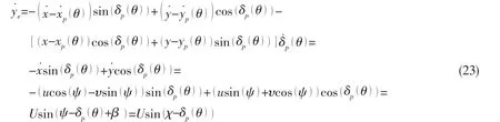

here the look-ahead distance△can be time-varying using the following equation[18]:

where ρ is the convergence rate of△.Inserting Eq.(24)into Eq.(23)gives:

2.2 LOS guidance law for a straight line and a circle
For a straight line,the PP frame is rotated around an angle α relative to the inertial North-East reference frame shown in Fig.4.Hence,the LOS guidance law in Eq.(24)can be computed as:

For the circle having non-zero curvature,the LOS guidance law χcis time-varying.By analyzing Fig.5,this angle can be calculated as:


Fig.4 LOS guidance law for a straight line

Fig.5 LOS guidance law for a circle
3 Dynamic position mathematical model
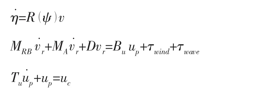
Motivated by the actuator dynamics adopted by Morishita and Souza[15]and Fossen and Berge[14],the mathematical model for path following can be modified as:

where η=[x,y,ψ]Tis the generalized position in the inertial reference frame;The body-fixed velocitiy is defined by the vector v=[u,υ,r]T;R(ψ)is the rotation matrix;M∈R3×3is the inertia matrix,D∈R3×3is the damping matrix,Bu∈R3×nis the configuration matrix with n actuators.up∈Rn×1is the return of the propeller thrusts;b∈R3×1is the slow varying environmental forces including wind,waves,currents as well as those induced by actuators;Tn∈Rn×nis a dialogue matrix of positive time constants;uc∈Rn×1is the vector of control outputs determined by the controller;Considering the saturation of the actuators,the control forces in surge,sway and yaw can be limited and represented as:
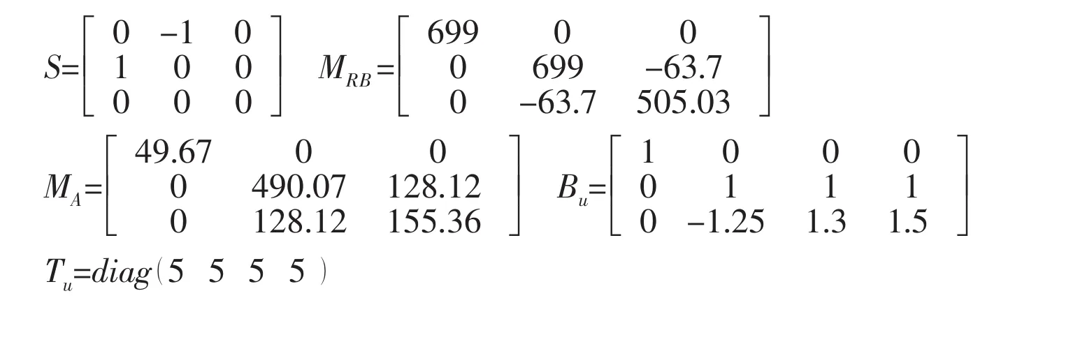
where umax∈R3×1and umin∈R3×1are the vectors with maximum and minimum saturation values.Specially,the matrices used in the nonlinear maneuvering model can be given as:
4 Control system design
Breivik[19]proposed a two-step backstepping controller for path following without actuator dynamics.In this Chapter,the modified control system design with actuator dynamics will be separated into three parts using a backstepping control.The process of the control system design will be stated as follows.
Defining the projection vector h:

The first error variable z1is defined as:

where ψdis the LOS guidance law angle χ given in Chapter 3.For a straight line,ψd=χsand ψd=χcfor a circle.Similarly,the second error variable z2can be defined as:

Step 1:Defining the first Lyapunov Function(LF)as:

The differentiation of Eq.(36)gives:

Inserting Eq.(35)into Eq.(37)gives:

Thus,the stabilizing function α13can be chosen as:

where c1>0 and Eq.(38)will become:

Step 2:Defining the second Lyapunov Function(LF)as:

The differentiation of Eq.(41)gives:

Based on Eqs.(30)and(35),we will have the following result:

Thus Buupcan be chosen as the second stabilizing function α2.Hence,Eq.(42)can be rewritten as:

The second stabilizing function can be designed as:

where K2is a positive diagonal matrix and the adaptive integral action can be chosen as:

Step 3:Defining the second error variable z3:

The third Lyapunov Function(LF)can be expressed as:

The differentiation of Eq.(48)with the insertion of Eqs.(31),(44)and(45)gives:

Hence,the control law can be given by:
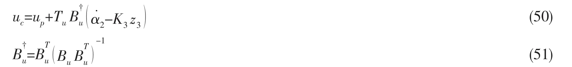
where K3is a positive diagonal matrix.In path following,we want that the ship moves forward with the given surge speed udand also desire that the sway velocity of the vessel is kept at zero.For the heading angle control,the stabilizing function α13will be used.Thus,the stabilizing functions α1can be written as:

5 Simulation results
To evaluate the performance and robustness of this method,the computer simulation with the waypoints given in Tab.1 has been used.This work is based on an over-actuated offshore supply vessel model.The configurations of the actuators are shown in Tab.2.The vessel hydrodynamic coefficients of the matrices M and D used in Chapter 4 are calculated by Computational Fluid Dynamics(CFD)and given in Tab.3.To take into account the differences between the realistic model and the model used in Chapter 3,the vessel realistic model will be adopted in this simulation where the wind,current and wave forces are calculated separately(Appendix A).Therefore,the calculated matrices M and D will be used for controller design and the vessel realistic model in Appendix A will be adopted to represent the real ship motion. The matrices used in this paper are illustrated in Appendix B.The other parameters related to the controller,desired speed and initial states are displayed in Tab.4.
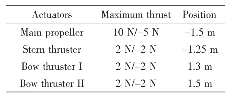
Tab.2 The configurations of the actuators

Tab.3 The used parameters for the model ship
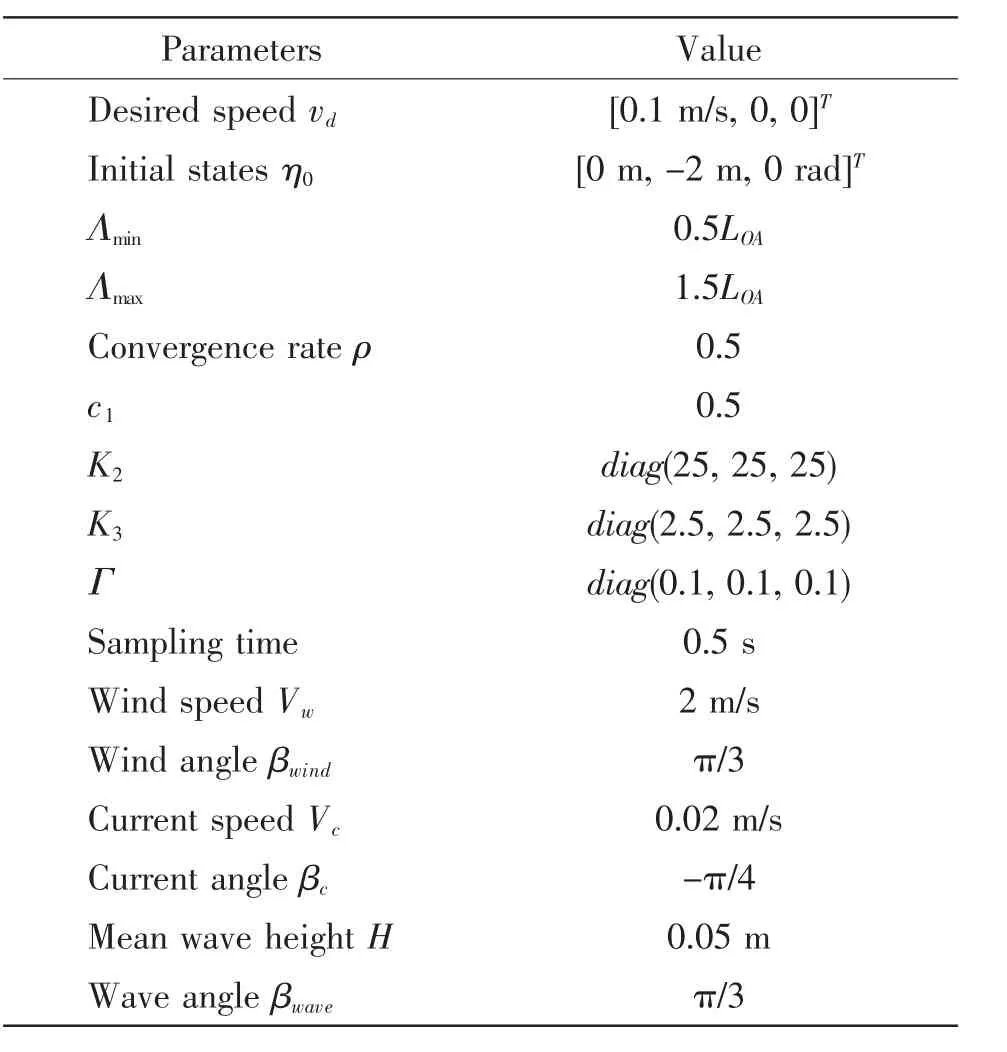
Tab.4 The other parameters used in the simulation
To illustrate the validity of the proposed method,the simulation will be adopted in the computer.The results of path following and heading angle tracking are depicted in Fig.6 and Fig.7.Fig.6 shows the path planning with the given waypoints and the ship can follow the smoothpaths consisting of straight lines and circle arcs.Fig.7 presents the desired heading angle generated by the LOS guidance law and the actual ship heading angle.The sharp change heading angle demonstrates that the ship locates in the circle arcs and the almost constant heading angle represents the ship locates in the straight lines.
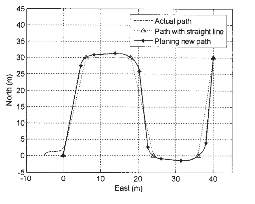
Fig.6 Path following for the model ship
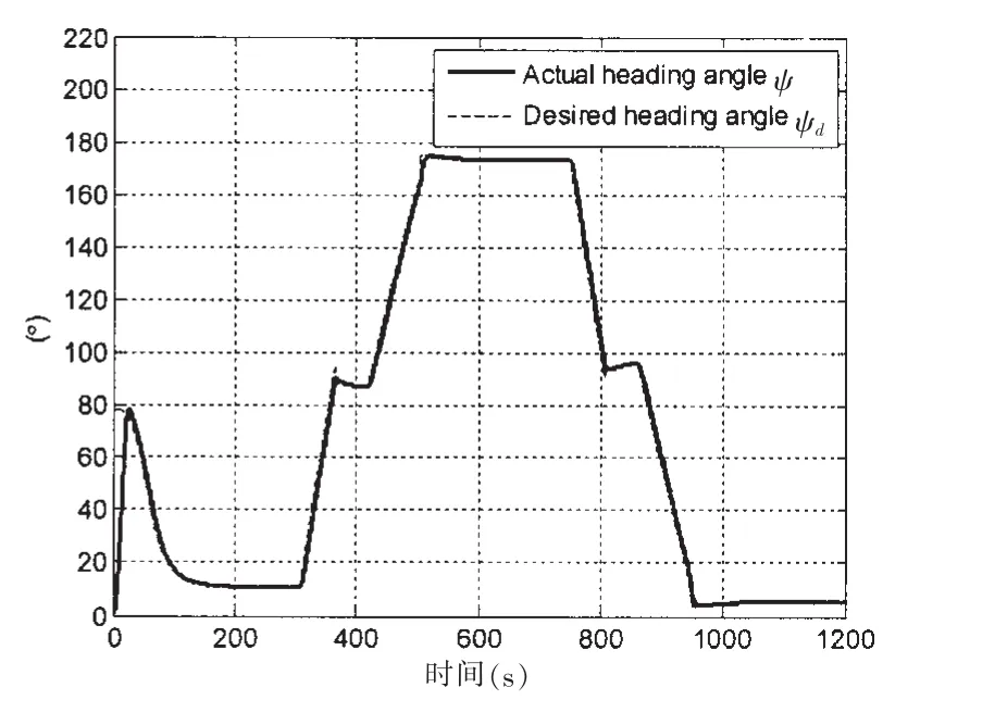
Fig.7 Actual yaw angle tracks the desired LOS angle
In order to demonstrate the advantages of including the actuators in the modified controller,the performances with actuator dynamics and without the inclusion of the actuator dynamics are compared shown in Fig.8(a)and Fig.8(b).Taking into account the actuator dynamics,the control outputs are smoother than those without actuator dynamics.The time lag between the control outputs and the real propeller forces caused by the actuator dynamics tends to retard the ship motion,and the controller without actuator dynamics will compensate for it by magnifying the control outputs.Thus,the control outputs without actuator dynamics have the sharp changes to the saturation values,which is impossible for the actuators to attain.As the bandwidth of the actuator dynamics is close to the bandwidth of the ship motion,the modified backstepping controller with actuator dynamics is suitable to have smoother control outputs.
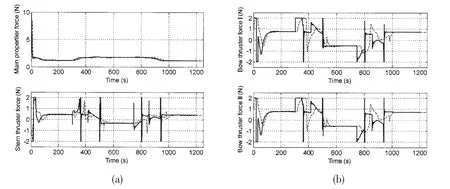
Fig.8 Control outputs with actuator dynamics(dashed)and without actuator dynamics(solid)
Fig.9 shows the ship tracks the given surge speed udperfectly.Fig.10 indicates the results of the integral action.It is worth noting that the bigger elements in the gain matrix Γ will make the bigger oscillation of the adaption forces.
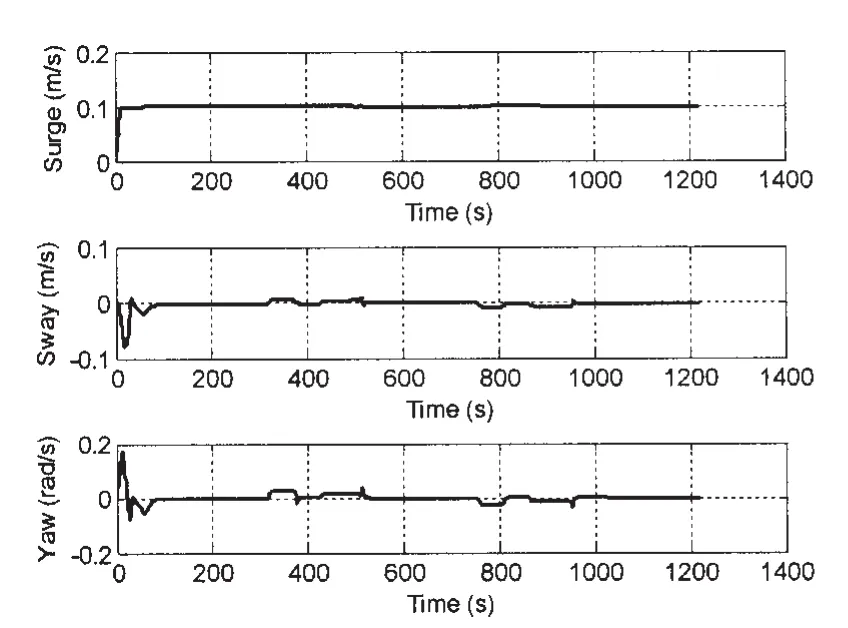
Fig.9 Ship velocity
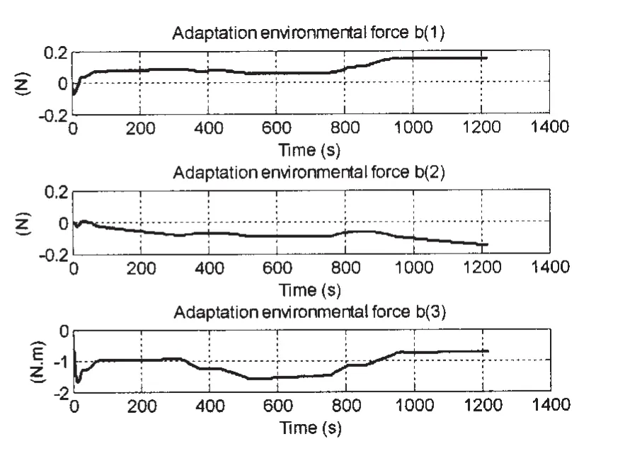
Fig.10 Behavior of the integral action
6 Conclusion
This paper demonstrates the planning of a continuous-curvature path with straight lines and circles by using a simple geometric method.In order to attenuate the oscillation of the control signal caused by the time lag,a modified backstepping controller with actuator dynamics is proposed to obtain a smooth control outputs.Integral action is adopted to adapt the slow varying environmental forces consisting of wind,wave and current forces.The stability of the closed-loop system with actuator dynamics is assured through Lyapunov stability analysis. Simulation results exactly confirm the good performance of the LOS guidance law and the control system.
[1]Fossen T I.Guidance and control of ocean vehicles[M].John Wiley&Sons,1994.
[2]Peymani E,Fossen T I.A Lagrangian framework to incorporate positional and velocity constraints to achieve path-following control[C].In Proceedings of 50th IEEE Conference on Decision and Control and European Control Conference (CDC-ECC),2011:3940-3945.
[3]Fossen T I,Breivik M,Skjetne R.Line-of-sight path following of underactuated marine craft[C]//In Proceedings of the 6th IFAC MCMC.Spain,2003:244-249.
[4]Skjetne R,Fossen T I,Kokotovic P.Output maneuvering for a class of nonlinear systems[C]//In Proceedings of 15th IFAC World Congress on Automatic Control.Spain,2002.
[5]Dubins L E.On curves of minimal length with a constraint on average curvature,and with prescribed initial and terminal positions and tangents[J].American Journal of Mathematics,1957:497-516.
[6]Breivik M,Fossen T I.Path following of straight lines and circles for marine surface vessels[C]//In Proceedings of the 6th IFAC CAMS.Italy,2004:65-70.
[7]Shanmugavel M,Tsourdos A,White B,Zbikowski R.Co-operative path planning of multiple UAVs using Dubins paths with clothoid arcs[J].Control Engineering Practice,2010,18(9):1084-1092.
[8]Lekkas A M,Dahl A R,Breivik M,Fossen T I.Continuous-curvature path planning using Fermat’s spiral[J].Modeling, Identification and Control,2013,34(4):183-198.
[9]Candeloro M,Lekkas A M,Soerensen A,Fossen T I.Continuous curvature path planning using Voronoi diagrams and Fermat’s spirals[J].Control Applications in Marine Systems,2013,9(1):132-137.
[10]Yuh J,Nie J,Lee C G.Experimental study on adaptive control of underwater robots[C].In Proceedings of IEEE International Conference on Robotics and Automation,1999,1:393-398.
[11]Sun Y C,Cheah C C.Adaptive setpoint control for autonomous underwater vehicles[C].In Proceedings of 42nd IEEE Conference on Decision and Control,2003,2:1262-1267.
[12]Skjetne R.The maneuvering problem[D].Ph.D.thesis,Norwegian University of Science and Technology,2005.
[13]Breivik M.Topics in guided motion control of marine vehicles[D].Ph.D.thesis,Norwegian University of Science and Technology,2010.
[14]Fossen T I,Berge S P.Nonlinear vectorial backstepping design for global exponential tracking of marine vessels in the presence of actuator dynamics[C].In Proceedings of the 36th IEEE Conference on Decision and Control,1997,5:4237-4242.
[15]Morishita H M,Souza C E S.Modified observer backstepping controller for a dynamic positioning system[J].Control Engineering Practice,2014,33:105-114.
[16]Fossen T I,Pettersen K Y.On uniform semiglobal exponential stability(USGES)of proportional line-of-sight guidance laws[J].Automatica,2014,50(11):2912-2917.
[17]Fossen T I.Handbook of marine craft hydrodynamics and motion control[M].John Wiley&Sons,2011.
[18]Lekkas A M,Fossen T I.A time-varying lookahead distance guidance law for path following[C]//In Proceedings of 9th IFAC Conference on Manoeuvring and Control of Marine Craft.Italy,2012.
[19]Breivik M,Fossen T I.Path following for marine surface vessels[C]//In Proceedings of the OTO’04.Japan,2004:2282-2289.
[20]Skjetne R.Smogeli O N,Fossen T I.A nonlinear ship manoeuvering model:identification and adaptive control with experiments for a model ship[J].Modeling,Identification and Control,2004,25(1):3-27.
Appendix A:The realistic ship model
The mathematical model proposed by Fossen[17]for the ship can be given as:
where MRBis the rigid-body inertial matrix and MAis the added inertial matrix.The term τwindand τwaveare the wind and wave forces.For the detailed calculations of wind and wave forces, see Fossen,reference(P188-199)[17].The term vr∈R3×1is the relative speed vector with respect to the effect of currents.The relation between vrand v can be expressed as[20]:
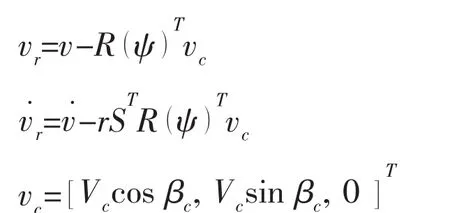
where Vcand βcare the current speed and direction in the inertial reference frame.
Appendix B:Some matrices used in the simulation
The following matrices are used in this paper:
基于动态执行机构的船舶循迹反步积分控制
瞿洋a,b,徐海祥a,b,余文曌a,b
(武汉理工大学a.高性能船舶技术教育部重点实验室;b.交通学院,武汉430063)
文章针对连续曲率路径,用一种简单的几何方法生成连续曲率的路径。基于该几何方法生成的连续路径,文中利用line-of-sight(LOS)引导律解决了循迹控制中横向偏差最小的问题。为了减弱控制输出的振荡和获得平滑的控制输出,一种基于动态执行机构的改进反步积分控制器在过驱动船舶循迹控制中得到了应用。值得注意的是,文中用积分操作来抵抗风浪流环境力。数值分析结果展示了该控制器的有效性。
循迹控制;路径规划;LOS引导律;反步积分控制;动态执行机构
U674.38
:A
国家自然科学基金项目资助(61301279,51479158)
瞿洋(1992-),男,武汉理工大学交通学院硕士;
U674.38
:A
10.3969/j.issn.1007-7294.2017.06.004
1007-7294(2017)06-0685-13
徐海祥(1975-),男,武汉理工大学交通学院教授,博士生导师;
date:2016-12-16
Supported by the National Natural Science Foundation of China(61301279,51479158)
Biography:QÜ Yang(1991-),male,master candidate;XÜ Hai-xiang(1975-),male,Ph.D,professor, corresponding author,E-mail:qukaiyang@163.com;YÜ Wen-zhao(1989-),male,Ph.D.
余文曌(1989-),男,武汉理工大学交通学院讲师。
猜你喜欢
杂志排行

船舶力学的其它文章
- Characteristic Study of the Random Wind Load on Semi-submersible Tender Support Platform
- Comparison on Different Schemes of Direct Numerical Simulation for Low/medium Reynolds Flow
- Sound Field Separation Technique Based on Acoustic Radiation Modes
- Mechanical Behavior Analysis for Unbonded Umbilical under Axial Loads
- New Impulsive Factor in Representing Cabin Damage under External Air Explosion
- Numerical Simulation of Nonlinear Sloshing Waves in Three-dimensional Tank based on DBIEM