An adaptive neuro-fuzzy sliding mode controller for MIMO systems with disturbance
2017-05-28MahmoudSaafanMohamedAbdelsalamMohamedElksasSabrySarayaFayezAreed
Mahmoud M.Saafan*,Mohamed M.Abdelsalam,Mohamed S.Elksas,Sabry F.Saraya,Fayez F.G.Areed
Computers and Control Systems Engineering Department,Faculty of Engineering,Mansoura University,Egypt
1.Introduction
Ammonia(NH3)is one of the most widely used chemicals in industry.NH3is produced from the reaction between nitrogen gas(N2)and hydrogen gas(H2).The reaction for ammonia production is described as[1–7]:

There are six steps for ammonia synthesis process:hydrogen production stage,nitrogen addition stage,removal of carbon monoxide stage,water removal stage,removal of carbon oxides,and finally,synthesis of ammonia stage.The flow chart of the ammonia process is shown in Fig.1.An ammonia reactor with quenching cooling and beds is shown in Fig.2.[6].
The functions of CO conversion unit are reducing the COslip,providing the highest yield of hydrogen,and maximizing the CO2production to be used in urea plant[4–6].

The reaction is reversible and exothermic,pressure has no effect on it,and an increase of steam increases the products.Because the reaction is exothermic,as the temperature increases the extent of conversion will decrease.To overcome that,we use a two stage system with suitable inter-cooling stages.This is the reason to use a high temperature reactor and low temperature reactor.Low temperature reactor allows water shift reaction to proceed at low inlet temperature limited by the dew point temperature.Usually,the inlet temperature is 15°C greater than the dew point temperature.According to the water shift reaction,as the steam increases the conversion of CO will increase too.But as the steam decreases the following bad effects will happen:
–The conversion of CO will decrease.
–Steam is used to moderate the reduction effect,and without steam the catalyst will be over-reduced to metallic iron.If this happens the structure of the catalyst will be changed and be weaker also metallic iron reacts with CO forming iron carbide which promotes other side reactions such as:

Carbon will make a layer on the catalyst bed and increase the pressure drop on the reactor.The gas enters through the inlet of the high temperature reactor at a temperature of nearly 345°C.For protection of the condensation of water droplets the catalyst bed is covered by a layer of ceramic balls,where,the droplets of water vaporize on it.The reactor contains two layers,where,the reaction is proceeded on reaching 2.65 vol%.As the temperature of the gas inlet of the low temperature reactor must be around 198°C,so the gas that exits the high temperature reactor must be cooled.For this purpose,the gas is passed through the exchanger to exchange with the gas inlet methanator.Sometimes this exchanger is not used to increase the temperature of the inlet of the methanator,it is only used during start up or to increase the methanator inlet temperature to about 300°C.Then it is sent through the gas cooler,where the gas temperature is decreased from 410 °C to 198 °C by exchanging with boiler feed water[4–6].
Urea is a chemical compound.The formula for urea is NH2CONH2.Urea is used mainly as a nitrogen fertilizer to grow crops,to produce urea formaldehyde resins,in wood industries,pharmaceutical industries and as an additive to animal food.Urea is produced by two chemical reactions, first,between ammonia and carbon dioxide.This reaction produces ammonium carbamate,which then reacts to produce urea.The first reaction is exothermic and fast,while the second reaction is endothermic and slow,the ammonium carbamate dehydrates to produce urea(NH2CONH2)and water(H2O).The two reactions are described as[8–9]:
–The reaction of condensation


Fig.1.Flow chart of ammonia synthesis process.

Fig.2.Ammonia reactor with quenching and bed sections.
The condensation is dependent on condensation temperature,pressure of reactor,the molar ratio between ammonia and carbon dioxide(NH3/CO2ratio),and molar ratio between water and carbon dioxide(H2O/CO2ratio).The molar ratio between ammonia and carbon dioxide must be equal to 3[10]in order to achieve the maximum urea conversion and reduce the pollution effect.There are five steps for urea plant:synthesis stage,recirculation stage,desorption and hydrolyzation stage,evaporation stage,and finally,granulation stage.The block diagramofurea process is shown in Fig.3.The schematic representation of the urea process is shown in Fig.4.The schematic representation of the ammonia and urea processes is shown in Fig.5.
The NH3/CO2measurement in the outlet of the reactor indicates the molar ratio in the liquid phase.The normal operating range is between molar NH3/CO2ratios of about3.0 and 3.1.If the ratio is lower than 3.0 or higher than 3.1 the composition of the liquid in the reactor will deviate from optimum composition.In this case reactor outlet temperature will not be maximum,thus conversion of ammonia and carbon dioxide to urea in the reactor will be less.But all non-converted ammonia and carbon dioxide have to be recycledviaeither a high pressure heat exchanger or recirculation stage.Consequently a wrong NH3/CO2ratio will lead to higher steam consumption of the High Pressure Stripper as well as possibly more recycle of carbamate from the recirculation stage,which in its turn again will decrease ammonia and carbon dioxide conversion due to more water introduced into the synthesis section.The normal operating range is between 180 and 183°C.At an operating pressure of 136×105Pa–143×105Pa and with a normal quantity of water in the reactor,the latter temperature will never be exceeded.If the temperature in the reactor top is too low,this may be due to:The operating pressure being below the requirement,to a wrong NH3/CO2ratio,and the degree of condensation in the high pressure carbamate condenser being too high.Whenever the NH3/CO2ratio is wrong,the composition of the liquid in the reactor top will differ from the optimum,so that the temperature will not reach its maximum value either[9–12].
2.Mathematical Model of Ammonia Synthesis Reactor
The conversion of nitrogen and the feed ratio of nitrogen and hydrogen are represented as[3,8]:

The flow rates of nitrogen,hydrogen,methane,and ammonia are represented as:


The mole fractions of nitrogen,hydrogen,methane,air,and ammonia can be evaluated from flow rates which are represented as:


Fig.3.Block diagram of urea synthesis process.

Fig.4.Schematic representation of the urea process.


Fig.5.Schematic representation of the ammonia and urea processes.
2.1.Bed modeling
The mathematical model of the ammonia reactor consists of one model for each bed.Each bed is discretized into ten segments,and is represented by a mass and energy balance[8].

The subscriptqrefers to the quench steam,brefers to the reactor flow before the quench,and mix refers to the reactor flow after the quench.T,C,andMrefer to temperature,concentration of ammonia and mass flow,respectively.
2.2.Heat exchanger modeling
The relation between in-and outlet temperatures

whereTi,Toand ε are reactor in temperature,outlet temperature,and heat exchanger efficiency,respectively.
Table 1 illustrates previous variable's definition.
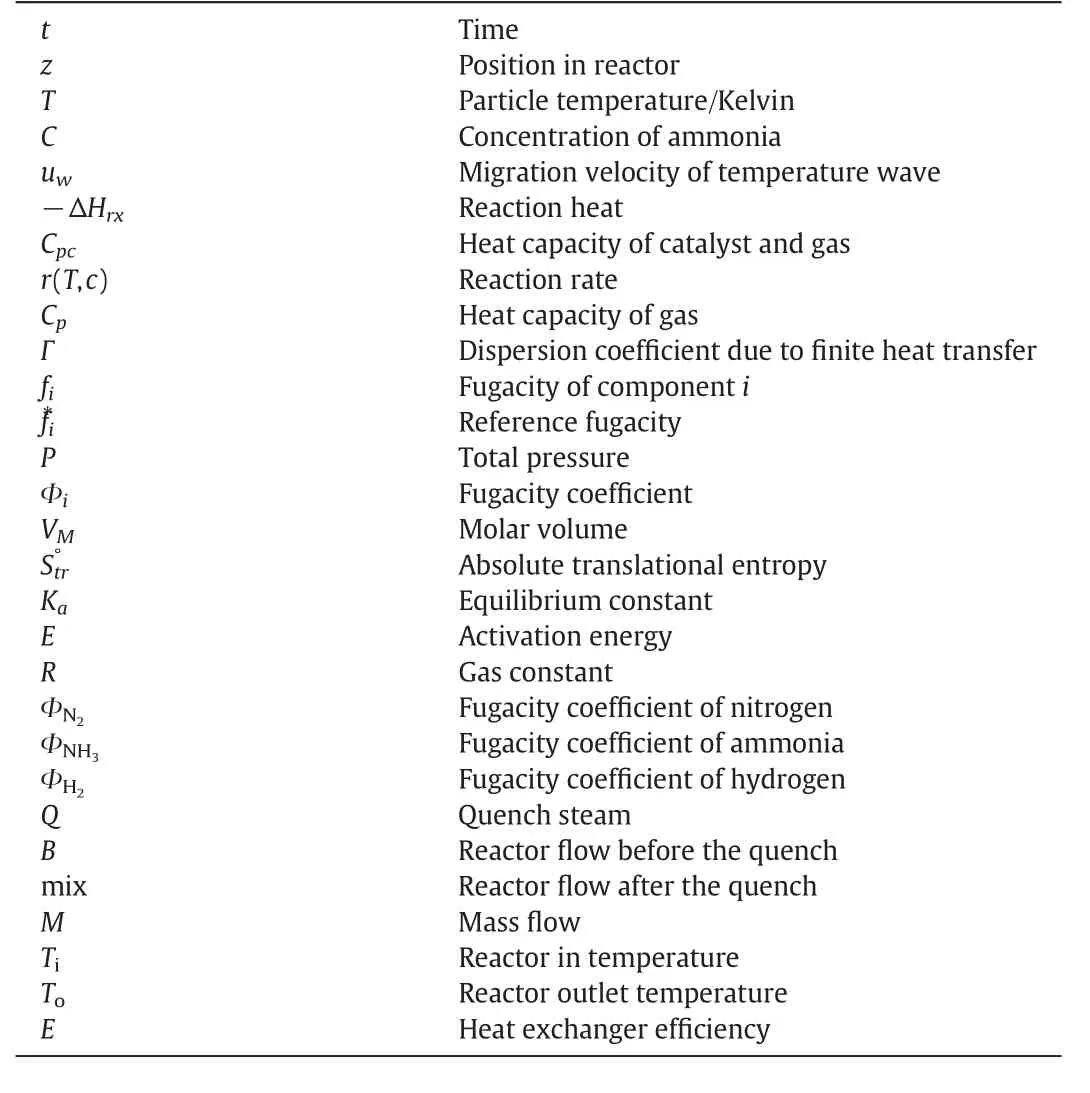
Table 1Variable's definition of NH3 reactor model
3.Mathematical Model of Urea Synthesis Reactor[9,12–13]
Eqs.(5)and(6)will be converted as ε1and ε2while the overall conversion as ε1ε2=ε:

where,FU,FCandFDare the flow rates of urea,carbamate and carbon dioxide respectively.FCi,FDiandFUi,are the initial flow rate of urea,carbamate and carbon dioxide respectively.
The flow rates of ureaFU,carbamateFC,carbon dioxideFD,ammoniaFN,waterFHand total rateFTwhich is the sum of all individual flow rate are represented as:

whereaandbare ammonia and water feed ratios which are represented as:

where,k1Fandk2Fare kinetic for the forward two urea reaction equations,Cd,Cc,andCuare molar flow rates for carbon dioxide,carbamate and urea,andk1andk2are equilibrium constants.


Eq.(58)is true when the temperature is in the range of 293–405 K but in the range of216–304 Kfor Eq.(59).When the reactor parameters are changed or disturbed,the resultant effect can be described as:slower rate of reactions,reversible reactions,reduction in the concentration of the reactor outlet,change in the NH3/CO2ratio,reduction in the CO conversion,and reduction the quantity of the ammonia and urea productions.So,it is needed to design adaptive and intelligent controllers to overcome the parameter variables and external disturbances that affect the ammonia–urea reactors.In designing a control system for ammonia and urea the system is subjected to:
–Parameter variations.
–Parameter uncertainty.
–Due to the complexity,the system is divided into subsystems.Some subsystems have influences to other subsystems as disturbances.
–Dynamical system characteristics vary considerably over the operating regime.
–The system is exposed to a fast and wide range of parameter variations.
–Some processes are complicated to be modeled.
So we want to design a smart robust controller as a neural network,fuzzy controller and sliding mode control that can control a process with the previous challenges.In this paper,three design methods are suggested to achieve a stable outlet concentration of ammonia and urea,stable reaction rate,an increase in the conversion of CO to reduce the pollution effect,and an increase in the ammonia and urea productions,keeping the NH3/CO2ratio equal to 3 to reduce the unreacted CO2and NH3,and the two reactors'temperature in operating ranges.The first method is based on AMPC controller techniques.This paper is arranged as follows.Section 2 represents the mathematical model of the ammonia synthesis reactor.Section 3 represents the mathematical model of the urea synthesis reactor.Section 4 describes the suggested method Adaptive Model Predictive Control.Section 5 describes the suggested method Adaptive Neural Network Model Predictive Control.Section 6 describes the suggested method Adaptive neuro-fuzzy sliding mode controller.Section 7 presents the simulation results obtained from the ammonia and urea synthesis reactors.Then,a comparison analysis between three methods and then,a comparison analysis with previously related works were performed.
4.Adaptive Model Predictive Control(AMPC)
AMPC is an optimal control method based on optimization techniques.The future output of the plant and the inputs of controller are predicted using a model of system and optimized at regular intervals.A dynamic system is used to predict the future output of the plant.AMPC is shown in Fig.6.The process can be described by a discretetime and state space model[13–16]:

where,A,B,and C are state matrices,X represents the process state vector,u is the input vector,y is the output vector,Wis the state disturbance,and ξ is the measurement noise.
The noise ξ and state disturbanceWare independent Gaussian noise with zero mean.
Φ is a function used to minimize values of squared state and input and includes Q and R,which are separate state and input weight matrices.

The plant output is used to obtain an optimal state estimate^Xk k.

where,the optimal inputuk=−Kc^Xkk.
AMPC uses a Kalman filter(KF)to update the states of the controller.It includes states of the plant,states of the disturbance,and measurement noise states.KF requires two gain matrices L and M.The AMPC controller depends on the variation of noise parameters and disturbance to calculate the L and M gains.

where,R,N,and Q are constant matrices defined as in the state estimation of AMPC.Pkk−1is the state estimate error matrix at timeKbased onk−1 time.
5.Adaptive Neural Network Model Predictive Control(ANNMPC)
Predictive future plant is based on the prediction of the potential control signals to be controlled.The optimization block is used to optimize the plant performance[17].The ANN is used to represent the nonlinear model of the plant.ANNs are adaptable dynamical systems that are less sensitive to variations of parameters,and estimate the functions of input–output.The proposed ANN structure of this adaptive NN controller is shown in Fig.7.The proposed ANNMPC contains two networks,the first network is neural network identification(NNI).The error of NNI between the output of the neuralyNN(k)and the plant outputy(k)is computed by the back propagation algorithm.The error function to be minimized is where,mandnare delayed elements of the vectors U and Y starting from the time instant(k−1).

The weights of NNI are adjusting the gradient descent in order to minimize the cost functionJ(k).The adapted weights are represented by


Fig.6.Adaptive Model Predictive Control.
where α is a learning rate.
The second network is the neural network predictor(NNP).The new weights of NNP and the optimization block are used to compute the predictive control signal to be applied to the plant.
6.Adaptive Neuro-fuzzy Sliding Mode Controller(ANFSMC)
The sliding mode controller(SMC)is robust control to uncertainty plants and insensitive to any disturbances.Unfortunately,the chattering can affect the system behavior significantly[6].Another control method is based on adaptive neuro-fuzzy inference system(ANFIS)with SMC.The flow chart of ANFSMC is shown in Fig.8.The block diagram of ANFSMC is shown in Fig.9.
ANFIS is divided into artificial neural network(ANN)and fuzzy inference system.The structure proposed of ANFIS consists of five network layers.The structure has two inputs(x,y)and produces one output(f).The ANFIS structure is shown in Fig.10.All nodes in the first layer are adaptive and every node contains a triangle membership function[18–21].

Fig.7.Adaptive Neural Network Model Predictive Control.


Fig.8.Flow chart of ANFSMC.
where,iandlare the numbers of node and layer respectively andOliis the output of the node.
All nodes in the second layer are fixed and they multiply the signal before outputting as shown in the equation:


Fig.9.Block diagram of ANFSMC.

Fig.10.Structure of ANFIS.
Also,all nodes in the third layer are fixed and perform a normalization of the strength from the second layer.The output of each node is represented as:

All nodes in the fourth layer are adaptive and the output is calculated from the product of the normalized strength and a first order polynomial and represented as:

where,p,q,x,y,andr,are parameters which are referred to as consequent parameters in fuzzy rules.Finally,a single node in the fifth layer which is computing the overall output described by:

The ANFIS controller combines the capability of neural network learning and the ability of fuzzy reasoning.The ANFIS is used to eliminate the chattering introduced by SMC.While,the combination of the fuzzy control and the SMC causes the reduction of the fuzzy rules significantly.ANFSMC is divided into two control signals.The first signal is equivalent controllerueq.Usingsands˙ to ANFIS structure to calculate the equivalent control signal.The second signal is hitting controluh.It is used to eliminate the chattering by using fuzzy logic.Steps of the ANFSMC technique.
•Set the input and output of the plant.
•Update the parameters of the ANFSMC technique.
•Using defuzzification process to calculate the output of the ANFSMC technique.
•Output of the controller added with disturbances is given to system.
•Repeat the steps until converge the optimal solution.
7.Simulation Results
The feed temperature of ammonia reactor has been disturbed for about 30%from the regular feed temperature from 100 min to 230 min.This is shown in Fig.10.The bed3 outlet temperature,ammonia concentration,and CO conversion due to this disturbance are shown in Fig.11.
When the feed temperature is reduced to 210°C,high bed3 outlet temperature oscillations occurred as shown in Fig.12a.The temperature drop was about 36.5%from the steady state value at 207 min.As in Fig.12b,high oscillations in the ammonia outlet concentration,are reduced to about 63.8%from its steady state value at 207 min.As in Fig.12c,high oscillations in the conversion of CO,are reduced to about 32.4%from the normal value.The system has oscillations for about 200 min.Also,this disturbance that has occurred in the ammonia reactor has a strong influence and impact significantly on the urea reactor.The ratio of ammonia to carbon dioxide is affected by this disorder,as shown in Fig.12d.The NH3/CO2ratio is reduced to 0.497.The urea reactor temperature is also shown in Fig.12e,with a high oscillation,which is reduced to about 35.75%from its steady state stable value.The urea concentration is shown in Fig.12f,with high oscillation and drop from 29.6%to 9.2%at 207 min.All oscillations that occurred in the ammonia urea reactor gradually increased at the beginning of the disturbance that has happened to the feed temperature,then gradually decreased when removing this disturbance.

Fig.11.Disturbed feed temperature.
The originality of this paper is dealing with the total production line of urea starting from nitrogen and hydrogen then ammonia production till urea outcome with external disturbances and parameter variations to achieve the following objectives:
1.Stable ammonia concentration.
2.Reduce pollution effect by increase the CO2conversion.
3.Increase the ammonia and urea production.
The most diffuse model for ammonia and urea is used,with compatibility with several reactors in our country.

Fig.12.Disturbed ammonia urea reactors.a.Bed3 outlet temperature.b.NH3 concentration ofbed3.c.COto CO2 conversion(%).d.NH3/CO2 ratio.e.Urea reactor temperature(°C).f.Urea concentration.For the proposed Adaptive Model Predictive Control,disturbed ammonia–urea reactors using AMPC for temperature disturbance are shown in Fig.13.Bed3 outlet temperature curve is shown in Fig.13a.It has oscillations from 100 to 130 min and from 210 to 227 min,which reach their minimum value at 431.5 °C then stabilize at 500 °C.The NH3 concentration of the bed3 curve is shown in Fig.13b.It has very small oscillation for about 15.3 min then the system stabilizes with 31.38%,at 150 min the system stabilizes with 30.11%NH3 concentration.The conversion of CO is shown in Fig.13c.It has small oscillation and it has dropped for about 3.9%from its steady state value then the system stabilizes with 96.5%.The NH3/CO2 ratio curve is shown in Fig.13d.It has very small oscillations at 100 min,which reach their minimum value at 2.9.The urea reactor temperature and urea concentration are shown in Fig.13e–f.There are small oscillations.The urea reactor temperature is stabilized at 181.6 °C.The urea concentration is about 30.23%.The system is stabilized approximately after 15 min.
The control algorithm is better due to online learning for the neural network and fuzzy logic rather than using off-line learning as several issues.Table 2 presents the comparison analysis between different related works and the three suggested methods.It's observed that the proposed Adaptive neuro-fuzzy sliding mode controller succeeded in avoiding the external disturbances and parameter variations with the adaptive neural network model predictive controller proposed and Adaptive Model Predictive Control.Every control system can overcome the disturbances till certain limits.Due to the differences operation status,resources availability,technology in several ammonia and urea manufacturers,ANFSMC has achieved the fast recovery time without any oscillations.It takes 2.7 min to overcome the disturbance.While AMPC controller takes 15 min,and ANNMPC takes 11 min.The NH3concentration is 31.3%for ANFSMC,30.11%for AMPC,and 30.4%for ANNMPC.The bed3 outlet temperature is 510 °C for ANFSMC,500 °C for AMPC,and 502°C for ANNMPC.The CO conversion is 98.7%for ANFSMC,96.5%for AMPC,and 97.2%for ANNMPC.The urea concentration is 31.34%for ANFSMC,30.23%for AMPC,and 30.4%for ANNMPC.The urea reactor temperature is 182 °C for ANFSMC,181.6 °C for AMPC,and 182 °C for ANNMPC.Moreover,this result is compared to other publications for more validation.F.G.Areedet al.,presented a PID and Decoupled Sliding Mode Controller(DSMC)to overcome the disturbances of the ammonia reactor[6].For the PID controller the system suffers from high temperature oscillations.The controller takes a longtime 105 min which is a maximum time compared with the three suggested controllers to overcome the system.The NH3concentration was 29.3%which is still lower than the proposed controllers.For the DSMC the system suffers from low temperature oscillations.The controller takes a longtime 26.5 min which is a maximum time compared with the three suggested controllers to overcome the system.The NH3concentration was 28.94%which is still lower than the proposed controllers.E.Holter and M.Hovd proposed a feed forward controller to overcome the disturbances of the ammonia reactor[7].The system suffers from temperature oscillations with ripples±1%.The controller takes a longtime 50 min which is a maximum time compared with the three suggested controllers to overcome the system.Then the oscillations are reduced to±0.5%.

Fig.13.Disturbed ammonia–urea reactors using AMPC for temperature disturbance.a.Disturbed NH3outlet temperature using AMPC for temperature disturbance.b.Disturbed NH3 concentration using AMPC for temperature disturbance.c.Disturbed CO conversion using AMPC for temperature disturbance.d.Disturbed NH3/CO2 ratio using AMPC for temperature disturbance.e.Disturbed urea reactor temperature using AMPC for temperature disturbance.f.Disturbed urea concentration using AMPC for temperature disturbance.For the proposed adaptive neural network model predictive controller,disturbed ammonia–urea reactors using ANNMPC for temperature disturbance are shown in Fig.14.There are lightly oscillations at the start of the disturbances.The bed3 outlet temperature is stabilized at 502°C as shown in Fig.14a.The NH3 concentration of bed3 is about 30.4%as shown in Fig.14b.The conversion of CO is stabilized at 97.2%as shown in Fig.14c.The NH3/CO2 ratio curve is shown in Fig.14d.It has very small oscillations at 100 min,which reach their minimum value at 2.976.The urea reactor temperature and urea concentration are shown in Fig.13e–f.They have small oscillations.The urea reactor temperature is stabilized at 182 °C.The urea concentration is about 30.4%.The system is stabilized approximately after 11 min.

Fig.14.Disturbed ammonia–urea reactors using ANNMPC for temperature disturbance.a.Disturbed NH3 outlet temperature using ANNMPCfor temperature disturbance.b.Disturbed NH3 concentration using ANNMPC for temperature disturbance.c.Disturbed CO conversion using ANNMPC for temperature disturbance.d.Disturbed NH3/CO2 ratio using ANNMPC for temperature disturbance.e.Disturbed urea reactor temperature using ANNMPC for temperature disturbance.f.Disturbed urea concentration using ANNMPC for temperature disturbance.For the proposed Adaptive neuro-fuzzy sliding mode controller,disturbed ammonia–urea reactors using ANFSMC for temperature disturbance are shown in Fig.15.There are not any oscillations.The bed3 outlet temperature is stabilized at 510°C as shown in Fig.15a.The NH3 concentration of bed3 is about 31.3%as shown in Fig.15b.The conversion of CO is stabilized at 98.7%as shown in Fig.15c.The NH3/CO2 ratio curve is shown in Fig.15d.The urea reactor temperature and urea concentration are shown in Fig.15e–f.The urea reactor temperature is stabilized at 182°C.The urea concentration is about 31.34%.The system is stabilized approximately after 2.7 min.
8.Conclusions
The kinetic model for ammonia synthesis and urea synthesis reactors in industrial scale was developed and simulated by MATLAB in the present paper.AMPC,ANNMPC,and ANFSMC are suggested to overcome the external disturbances and parameter variations in order to increase the CO conversion to reduce the pollution effect in such ammonia reactor,increase the CO2which is used in urea production and reduce the unreacted NH3and CO2,and an AMPC controller was tested to compare with the ANNMPC and ANFSMC.ANFSMC is a robust controller that can overcome several challenges as mentioned before,and due to its smartness and learning capability,ANFSMC is preferred in several control problems.

Fig.15.Disturbed ammonia–urea reactors using ANFSMC for temperature disturbance.a.Disturbed NH3 outlet temperature using ANFSMC for temperature disturbance.b.Disturbed NH3 concentration using ANFSMC for temperature disturbance.c.Disturbed CO conversion using ANFSMC for temperature disturbance.d.Disturbed NH3/CO2 ratio using ANFSMC for temperature disturbance.e.Disturbed urea reactor temperature using ANFSMC for temperature disturbance.f.Disturbed urea concentration using ANFSMC for temperature disturbance.

Table 2The comparison analysis between different related works and the three suggested methods
[1]J.Morud,S.Skogestad,Analysis of instability in an industrial ammonia reactor,AICHE J.44(4)(1998)888–895.
[2]R.Angira,Simulation and Optimization of an Auto-thermal Ammonia Synthesis Reactor,International Journal of Chemical Reactor Engineering9(1)(2014)42–43.
[3]A.Murase,H.Roberts,A.Converse,Optimal thermal design of an autothermal ammonia synthesis reactor,Ind.Eng.Chem.Process Des.Dev.9(4)(1970)503–513.
[4]R.Baddour,P.Brian,B.Logeais,J.Eymery,Steady-state simulation of an ammonia synthesis converter,Chem.Eng.Sci.20(4)(1965)281–292.
[5]T.Mohammad,K.Azam,The Optimization of an Ammonia Synthesis Reactor Using Genetic Algorithm,International Journal of Chemical Reactor Engineering,6(A113),2008.
[6]F.G.Areed,M.A.Badr,S.F.Saraya,M.S.Elksasy,M.M.Abdelsalam,Decoupled sliding mode control for a multivariable nonlinear system,Int.J.Comput.Appl.55(6)(2012)25–32.
[7]E.Holter,M.Hovd,Feedforward for stabilization of an ammonia synthesis reactor,MSc.Thesis,Norwegian University of Science and Technology,Norwegian,2010.
[8]Z.Umair,et al.,Kinetic model for ammonia and urea production processes,International Conference on Process Systems Engineering,Elsevier 2013,pp.25–27.
[9]M.A.Satyro,et al.,Modelling urea processes:A new thermodynamic model and software integration paradigm,Chem.Eng.(2003).
[10]M.M.Saafan,M.M.Abdelsalam,M.S.Elksasy,et al.,A sliding mode controller for urea plant,IJCSIS J.14(3)(2016)115–126.
[11]M.Frejacques,Theoretical basis of the industrial synthesis of urea,Chimie et Industrie.60(1)(1948)22–35.
[12]S.Zendehboudi,G.Zahedi,A.Bahadori,et al.,A dual approach for modelling and optimization of industrial urea reactor,Can.J.Chem.Eng.92(3)(2014)469–485.
[13]I.M.Fahmy,et al.,Real-time control of industrial urea evaporation process using model predictive control,Chem.Eng.Process Technol.(2015),http://dx.doi.org/10.4172/2157-7048.1000227(2015).
[14]O.Mauricio,A.Manozca,J.J.Espinosa,J.Vandewalle,Control of the synthesis section of a urea plant by means of an MPC controller,Computer Aided Chemical Engineering21(06)(2006)1305–1310.
[15]A.Alanqar,M.Ellis,P.D.Christo fides,Economic model predictive control of nonlinear process systems using empirical models,AIChE J61(3)(2015)4953–4958.
[16]M.Shyamalagowri,et al.,Model predictive control design for nonlinear process control reactor case study,IOSR J.7(1)(2013)88–94.
[17]Z.Yu,Y.Liang,Design and realization of optimization system of urea production process based on BP neural network,ICCASM,10,2010,pp.368–371.
[18]M.Khaki,I.Yusoff,N.Islami,Application of the artificial neural network and neurofuzzy system for assessment of groundwater quality,Clean-Soil,Air,Water43(4)(2015)551–560.
[19]A.Al-Hmouz,J.Shen,R.Al-Hmouz,J.Yan,Modeling and simulation of an adaptive neuro-fuzzy inference system(ANFIS)for mobile learning,IEEE Trans.Learn.Technol.5(3)(2012)226–237.
[20]A.Swetapadma,A.Yadav,High-speed directional relaying using adaptive neurofuzzy inference system and fundamental component of currents,IEEJ Transactions on Electrical and Electronic Engineering10(6)(2015)653–663.
[21]L.Hung,H.Chung,Decoupled sliding-mode with fuzzy-neural network controller for nonlinear systems,Int.J.Approx.Reason.46(2007)74–97.
杂志排行

Chinese Journal of Chemical Engineering的其它文章
- Corrosion performance of Al–Al2O3 cold sprayed coatings on mild carbon steel pipe under thermal insulation☆
- Modelling of adsorption of textile dyes over multi-walled carbon nanotubes:Equilibrium and kinetic
- Integrated ozone–photo–Fenton process for the removal of pollutant from industrial wastewater☆
- Suppressing secondary reactions of coal pyrolysis by reducing pressure and mounting internals in fixed-bed reactor☆
- Multi-objective regulation in autohydrolysis process of corn stover by liquid hot water pretreatment
- Development of a new cleaner production process for cassava ethanol☆