Modelling of wave transmission through a pneumatic breakwater*
2017-04-26MaciejPaprotaWojciechSulisz
Maciej Paprota, Wojciech Sulisz
Institute of Hydro-Engineering of Polish Academy of Sciences, Gdańsk, Poland, E-mail: mapap@ibwpan.gda.pl
Modelling of wave transmission through a pneumatic breakwater*
Maciej Paprota, Wojciech Sulisz
Institute of Hydro-Engineering of Polish Academy of Sciences, Gdańsk, Poland, E-mail: mapap@ibwpan.gda.pl
A theoretical approach is derived to study interaction of linear water waves with an air bubble curtain used as a pneumatic breakwater. Modelling of wave transmission through an aerial barrier is a complex task due to a need to cover processes associated with wave-current interaction, effects of two-phase flows, wave damping, etc.. An initial boundary-value problem is solved by applying an efficient eigenfunction expansion method and a time-stepping procedure. The derived semi-analytical solution is used to study the effect of basic parameters of the model on wave dissipative properties of the pneumatic breakwater. Results show that wave damping by the breakwater is mainly affected by an air flow rate. The increased air discharge results in higher velocities of ascending bubbles and increases aerial barrier width. This leads to a substantial reduction of transmitted wave heights, especially for waves of intermediate length and short waves. In order to verify the applicability of the presented theoretical approach, laboratory experiments are conducted in a wave flume for different wave regimes and pneumatic breakwater characteristics. The analysis of a wave transmission coefficient calculated numerically and measured in the laboratory confirms that the derived model can be used for a certain range of wave conditions.
Surface waves, wave transmission, wave-current interaction, pneumatic breakwater, numerical modelling
Introduction
Breakwaters are typical structures designed to protect harbours and coastal areas against wave attack. There are several types of breakwaters applied in a coastal zone. Most of them are heavy and expensive constructions. The cost of breakwaters increases with water depth and with severity of wave climate. An attractive alternative to traditional breakwaters are pneumatic curtains. The idea is based on generation of a vertical barrier consisted of air bubbles emanating from a perforated pipe founded on the sea bottom. The application of the air bubble barrier leads to wave energy dissipation and reduces the height of transmitted waves. Pneumatic barriers have several advantages in comparison with traditional breakwaters. In particular, it is easy to install such a barrier, the cost of construction is very low, this type of installation does not disturb ship traffic and remains neutral for natural landscape. Moreover, generation of additional circulation helps to maintain good quality of sea water. Despite the obvious benefits, pneumatic breakwaters remain an interesting scientific subject rather than a real problem of maritime engineering practice. This is mainly caused by a high power demand of air compressors providing sufficient amount of air required for an operation of pneumatic breakwaters. Low efficiency of aerial barriers in damping longer waves is another important drawback of the solution. On account of these facts, pneumatic curtains can be applied as temporal protection against short waves (e.g., protection of harbour entrance or waterways during storm events)[1]or can be combined with other coastal protection structures such as submerged and floating breakwaters[2].
The idea to construct an aerial barrier as a breakwater was proposed in 1907. This method was successfully applied to protect Standard Oil Company pier situated in El Segundo in California against wave action. First investigations suggested that wave damping by the pneumatic breakwater is a result of a current induced by air bubble motion[3]. Experiments performed in Californian Institute of Technology seems to support this hypothesis[4]. The idea of experiments was to generate currents set up by air injection or by water jets. The application of two types of current generation led to similar wave damping efficiency. Evans[3]conducted experiments to study theinfluence of a water jet on wave energy dissipation. The mean velocity of the opposing surface current necessary for complete damping was found to be proportional to the square root of wavelength. The results were similar to the results of the theoretical study performed by Taylor[5]. Consecutive experiments were conducted by Hensen[6,7]. Two wave flumes of different size were used. The smaller one was 0.5 m deep and the larger 1.15 m deep. Wave breaking was one of the reasons for higher damping rate. Experiments conducted in the field led to an interesting conclusion that the application of Froude similarity law to calculate the amount of air for different model scales was not an appropriate approach[7]. Preissler[8]derived a formula for the amount of air necessary to reduce the height of the incident wave by a certain value when passing through a pneumatic breakwater based on experiments conducted in a wave flume. A summary of analytical and experimental study on pneumatic breakwaters was provided by Bulson[9]. He proposed a formula for the amount of air necessary for complete suppression of incident waves. Brevik[10]applied the theoretical method proposed by Taylor[5], the perturbation approach of waves propagating in the presence of current proposed by Longuet-Higgins and Stewart[11], and wave breaking criteria to solve a problem of wave energy dissipation by the pneumatic breakwater. The presence of air bubbles was neglected in his considerations. Iwagaki et al.[2]investigated the effectiveness of pneumatic breakwaters in damping waves in combination with other types of breakwater. They concluded that the waves passing over the submerged breakwater transfer a part of their energy to higher frequency waves which can be efficiently damped by the pneumatic breakwater. Wang et al.[1]derived a similarity law for the amount of air necessary to generate wave damping barrier of specified parameters based on experiments conducted in a wave flume for three different model scales (1:10, 1:15, 1:30). Zhang et al.[12]studied numerically the efficiency of an air bubble curtain by applying a numerical model to a mixture of water and air. They applied a VOF method and solved standardequations with additional source terms in the governing equations. The theoretical results were compared with experimental data and the agreement was reasonable. Modelling of wave interaction with an aerial barrier is a complex task. The problem is that it is necessary to take into account processes associated with wave-current interaction, effects of two-phase flows, wave damping, etc. Therefore, the modelling requires an application of a complex numerical approach and is a challenging task[12].
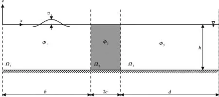
Fig.1 Definitions sketch and coordinate system
In this paper a novel theoretical approach is adopted to study transmission of water waves passing a submerged air bubble curtain used as a pneumatic breakwater. First, an initial boundary-value problem is formulated and solved by applying the eigenfunction expansion method and a time-stepping procedure. Then, the derived semi-analytical solution is used to study the effect of the basic parameters of the model on wave dissipative properties of the aerial barrier and applied to study damping performance of the pneumatic breakwater in different wave conditions. Finally, the developed numerical model is verified based on data from laboratory experiments.
1. Theoretical formulation
1.1Statement of a problem
The interaction of linear water waves with a pneumatic breakwater is considered (Fig.1). It is assumed that the fluid is inviscid and incompressible, the fluid motion is irrotational, and the sea bottom is horizontal and impervious. The area of action of the pneumatic breakwater with known damping properties is located in the middle section of the computational domain. A right-hand Cartesian coordinate system is selected such thataxis is horizontal and coincides with the undisturbed free surface andpoints vertically up-wards (Fig.1).
According to the assumptions the velocity vector,has a potentialsuch thatThe fluid motion in subdomainsis governed by the Laplace equation

and the Bernoulli equation

The fluid motion inside the area of action of the pneumatic breakwater is forced by rising bubbles. It is assumed that in this area linear damping law appliesOutside this area the fluid motion is governed by the classical equations for irrotational motion of incompressible and inviscid fluid

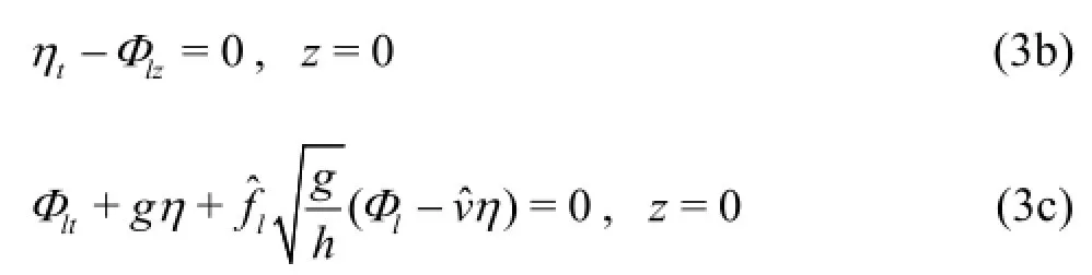
the kinematic and dynamic free-surface boundary conditions
continuity of pressure and mass flux conditions at each interface


and the bottom boundary condition

The set of Eqs.(3) represents the complete boundary-value problem of linear waves interacting with an aerial barrier formed by ascending bubbles. In the absence of vertical current generated by rising bubblesthe problem is reduced to the problem of waves propagating through a permeable structure of a rectangular cross section[16,17]and the presented solution can be applied to the problem of transmission and reflection of waves at permeable breakwaters.
1.2Solution
The solution is obtained by applying the eigenfunction expansion method. This technique has been shown to be very efficient in the modelling of the propagation and transformation of nonlinear waves[18-20], the generation of waves in a wave flume[21]and the nonlinear interactions of waves and currents[22]. The solution is sought in a computational domain that is sufficiently large to prevent wave reflection from lateral boundaries.
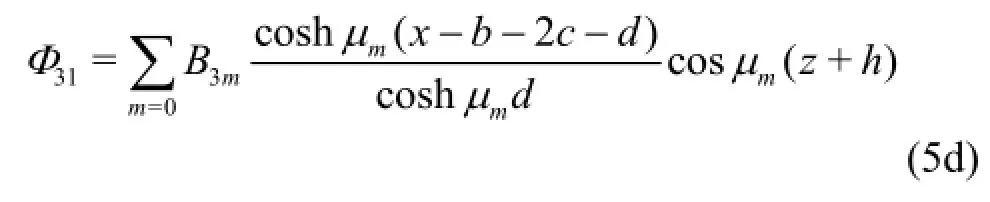
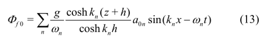
It is customary in boundary-value problems with inhomogeneous boundary conditions to decompose the solution into complementary components. Thus, the velocity potential,may be expressed as a linear combination of two velocity potentials given by


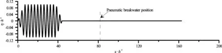
Fig.2 Initial conditions in terms of free-surface elevation
with corresponding eigenvalues:

In order to find a solution, the following form of the difference of potential components is introduced:
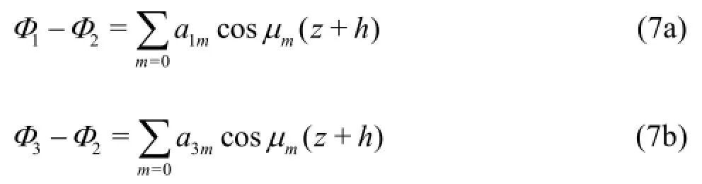
By substituting Eqs.(5) into Eq.(3e) and Eq.(3g), one obtains:


Introducing Eqs.(5) into Eq.(7a) atand Eqs.(5) into Eq.(7b) atgives:
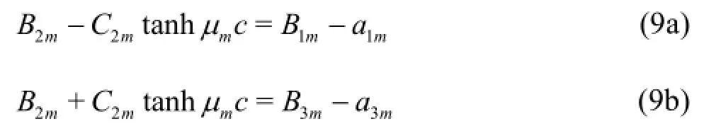
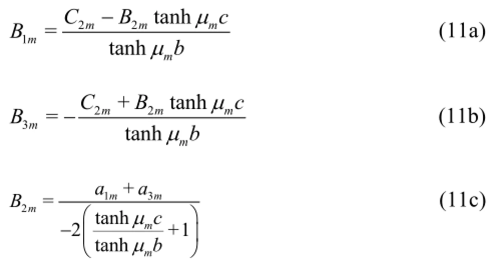
Finally, by substituting Eqs.(9) into Eqs.(8) and assuming thatone obtains:

The formulas (8) and (10) can be further simplified for high values ofε:

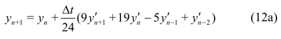
is combined with Adams-Moulton corrector
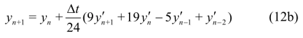
and with the boundary conditions (3b), (3c), (3d), (3f), to predict the velocity potential components and freesurface elevation at a new time step. Then, the Fourier transform is applied to determine the coefficientsof the eigenfunction expansions.
1.3Initial conditions
The solution requires initial values of the velocity potential,. Accordingly, the following formulae is applied to provide the initial conditions
The velocity of the current generated by ascending air bubbles requires a certain period of time to reach the stationary conditions. The distance of the wave train from the barrier guarantees that first waves of the wave train will pass the pneumatic breakwater after a steady current field generated by the breakwater is established. As mentioned before, a computational domain is sufficiently large to prevent wave reflection from lateral boundaries.
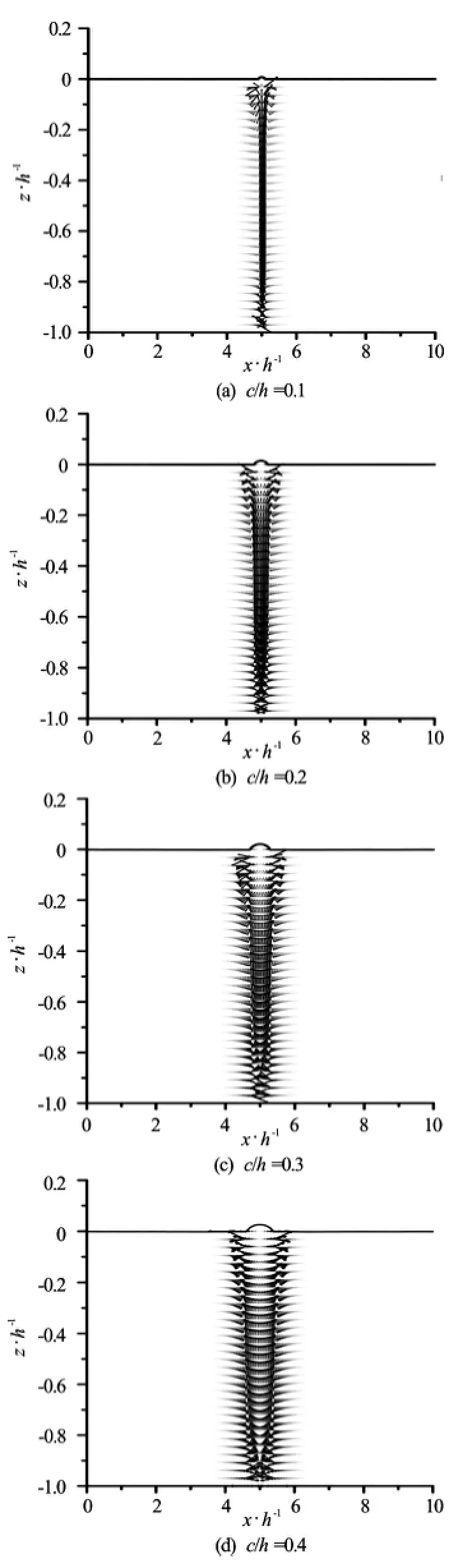
Fig.3 Effect of a barrier width on free-surface elevation and a velocity field generated by rising bubbles
2. Theoretical results
The numerical model derived to describe waveinteraction with a pneumatic breakwater is applied to study the effect of aerial barrier properties on wave transmission through the breakwater. The calculations are conducted for a wide range of wave frequencies and basic parameters of the model, including the length of the area of action of the pneumatic breakwater, the velocity of the current generated by rising bubbles, and the damping coefficient. Although the present analysis is limited to monochromatic regular waves, the model can be used to study transmission of irregular waves through the pneumatic breakwater including wave groups and random waves characterised by an arbitrarily chosen wave spectrum.
First the model is applied to examine the influence of the pneumatic breakwater parameters on the generated velocity field. In Fig.3 the velocity fields and free-surface elevations generated by rising bubbles are presented for different widths of the aerial barrier defined by the parameterrepresenting half of the barrier width.
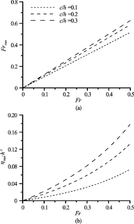
Fig.4 Effect of a vertical current velocity on the maximum horizontal current velocity and maximum free-surface elevation
Air bubbles ascending in the breakwater column enforce horizontal current along free surface. This current is directed away from the pneumatic barrier. However, the analysis shows that the direction of the current changes with depth. The current is directed towards the aerial barrier in the close vicinity to the bottom. The results show that the vertical current decreases with increasing width of the pneumatic breakwater. The maximum of the vertical velocity component is located in the middle of the aerial barrier. The results show that the fluid flow calculated by the present model is in reasonable agreement with the aerial barrier velocity field measured in the laboratory[24]. It is worth noticing that the free surface of water is lifted in the area of action of the pneumatic breakwater, which is a natural consequence of the vertically upward directed current generated by ascending air.
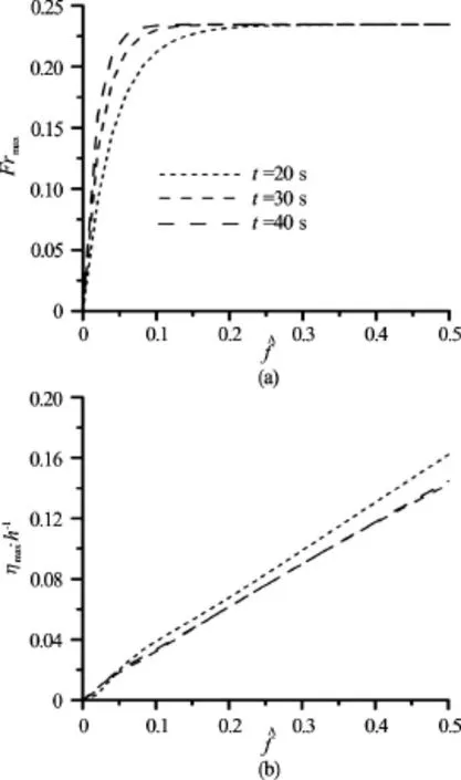
Fig.5 Evolution of steady state conditions with respect to the maximum horizontal current velocity and the maximum free-surface elevation in a function of a damping coefficient
The analysis shows that the magnitude of the current increases with increase inThe relationships between the Froude number of the maximum horizontal current velocity,, freesurface elevation and aerial barrier parameters, Froude number of vertical current velocity,and damping coefficient,are presented in Figs.4, 5. In Fig.4 it can be seen that the linear dependence between velocities of horizontal and vertical current occurs. The height of the lifted free surface at the position of the breakwater increases with the width and the vertical current velocity in a nonlinear way. Based on values of the width and the current velocity of an air-bubble plume obtained from the theoreticalformulas[25,26]the presented solution can be used to estimate the characteristic values of free-surface elevation and horizontal current velocity generated by ascending air for a given discharge from the pipes.
As it was already mentioned, the velocity of the current generated by ascending air bubbles requires time to reach the stationary velocity field. The analysis of the influence of the damping coefficient on the resulting current field revealed that the period of time needed for reaching the steady state is longer in the case of lower values of the damping coefficient (Fig.5). This information is of significant importance in the case of modelling of wave transmission with the derived method of solution at the stage of formulating the initial conditions.
The current generated by the pneumatic breakwater is one of the main factors affecting the transmission of waves through the pneumatic barrier. In front of the breakwater water waves propagate on the opposing current-their length is shortened and waves become steeper[22,27]. Then waves start to interact with the pneumatic breakwater. A part of wave energy is reflected by the barrier, another part is dissipated inside the area of action of the breakwater, and the remaining energy is transmitted into the downwave area. In this area waves propagate on the following currenttheir length becomes longer and wave amplitude decreases. The dissipation of energy inside the area of action of the breakwater is higher in the case of shorter waves. Increasing velocity of the current results in a decrease of the length of propagating waves and higher wave energy attenuation.
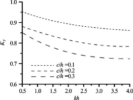
Fig.6 Effect of a barrier width on a transmission coefficient
The derived model allows to examine the effect of model parameters on transmission of waves through the pneumatic breakwater. Based on results from the numerical model a transmission coefficient was calculated for all test cases according to the formula
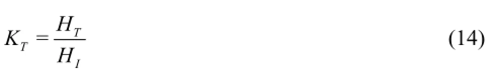
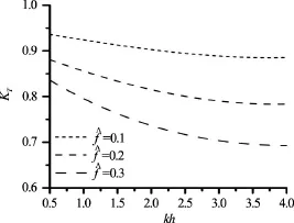
Fig.7 Effect of a damping coefficient on a transmission coefficient
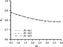
Fig.8 Effect of a vertical current velocity on a transmission coefficient
The width of the aerial barrier is an important parameter affecting wave transmission through pneumatic breakwaters. The analysis shows that increasing the width and the damping coefficient results in substantial reduction of transmitted wave height (Figs.6, 7). The magnitude of the current seems to have a less pronounced effect on the wave energy dissipation (Fig.8). The problem is that the magnitude of the current is strictly related to the discharge of air from perforated pipes, which affects also the width of the aerial barrier and it is difficult to determine what the effect of the current generated by the breakwater on wave transmission is. The dissipation rate of wave energy is higher in the case of shorter waves and remains constant regardless of the wavelength of the deepwater wave (Figs.6-8). The analysed effect of the coefficienton wave transmission and characteristics of a wavecurrent structure indicates that it is negligible for alltest cases considered and the simplified Eqs.(11) may be applied to calculate coefficientsin order to save computational time.

Fig.9 Experimental setup
3. Experimental verification
A series of laboratory experiments was carried out in the wave flume of Institute of Hydro-Engineering of Polish Academy of Sciences[28]. The wave flume is 64 m long, 0.6 m wide. Waves are generated by a programmable piston-type wavemaker. A porous wave absorber is located at the end of the flume to prevent wave reflection. A perforated pipe was installed on the wave flume bottom perpendicularly to the flume walls. The pipe with orifices was connected to a piston-type air compressor that can supply desired amounts of air for experiments. The orifices were equally spaced over the pipe length. The distance between orifices was 0.01 m and the orifice diameter was 0.0005 m. A standard rotameter was used to secure a fixed air amount supplied by the air compressor. The continuous aerial barrier was generated across the wave flume. Resistant-type wave gauges were installed in front of and behind the pneumatic barrier to measure free-surface elevation. The experimental setup is presented schematically in Fig.9.
Laboratory experiments were conducted for three water depthsThe wavemaker generated wave trains of regular waves of heightand wavelength. The parameters of the aerial barrier were modified by changing the amount of air supplied by an air compressor. The system of wave gauges registered free-surface oscillations in front of and behind the aerial barrier. For all wave cases experiments were conducted with and without air supplied to the pipe. It allowed to measure incident and transmitted wave height. The experiments were limited to non-breaking waves.
The effectiveness of the pneumatic breakwater was analyzed for different wave conditions on the basis of wave energy transmitted through the breakwater. The width of the aerial barrier and the vertical current speed were estimated based on theoretical formulas reported by Brevik[25]. The damping coefficient was determined based on experimental dataset and the application of the approach used by Sulisz[15]. According to Lorentz’s hypothesis of equivalent work, the damping coefficient is[15]

The recorded free-surface oscillations allowed to estimate the transmission coefficient for different wave cases according to the formula (14), and to compare the experimental data with the results provided by the derived model. In Figs.10-13 a comparison between theoretical results and experimental data is presented for three water depths.
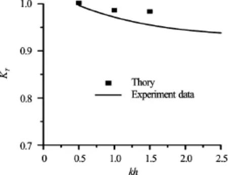
Fig.10 Effect of a wavelength on a transmission coefficient,
Experimental data confirm that the aerial barrier can serve as a breakwater especially for intermediate and deepwater water waves (Figs.10-12). The discrepancies between theoretical results and experimental data occurred mainly for deepwater waves due to wave instabilities.
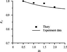
Fig.11 Effect of a wavelength on a transmission coefficient,

Fig.12 Effect of a wavelength on a transmission coefficient,
In Fig.13 theoretical results and the experimental data are plotted versus air outflow from the perforated pipe,Increasing the air flow rate results in the decrease of the transmission coefficient. The pneumatic breakwater performance is closely related with the performance of the air compressor. The comparisons show that theoretical results are in reasonable agreement with the experimental data.

Fig.13 Effect of an air supply on a transmission coefficient,
4. Summary
A theoretical approach was applied to study wave interaction with a pneumatic breakwater consisted of air bubbles emanating from a perforated pipe founded on the sea bottom. An original semi-analytical solution was derived to solve an initial boundary-value problem of interaction of water waves with an aerial barrier. The solution was obtained by applying the eigenfunction expansion method and a time-stepping procedure. The numerical model is very efficient and allows to test many different wave sequences (e.g., monochromatic waves, wave groups and irregular random waves) passing through the aerial barrier characterised by the set of selected parameters (e.g., air flow rate, barrier width). In the absence of a vertical current generated by ascending bubbles, the problem is reduced to the problem of waves propagating through a permeable structure of a rectangular cross section and the derived mathematical model can be used to investigate transmission and reflection of waves at permeable breakwaters.
The derived solution was applied to analyze the effect of basic parameters of the model, including the barrier width, the velocity of rising bubbles, and the barrier damping properties, on the velocity field. The analysis shows that air bubbles ascending in the barrier area generate both vertical and horizontal current components. The magnitude of the current increases with increase in the velocity of ascending bubbles. The current and air flow properties are crucial for the processes of wave interaction with the barrier and, in consequence, they affect the heights of reflected and transmitted waves.
Wave damping by the pneumatic breakwater is mainly affected by the air flow rate. The analysis shows that increased air discharge results in highervelocities of ascending bubbles and increases of the aerial barrier width lead to a substantial reduction of a transmitted wave height for waves of intermediate length and short waves. For high air flow rates some effect on the transmitted wave height is due to the opposing current generated by the barrier. The dissipation of energy inside the area of action of the breakwater is higher in the case of shorter waves. Increasing the velocity of the current results in decrease of the length of propagating waves and higher wave energy attenuation of the pneumatic breakwater.
Laboratory experiments were conducted in a wave flume to verify the derived model. The tests were carried out for different parameters of the aerial barrier and various wave conditions. The theoretical results are in reasonable agreement with the experimental data for the majority of wave cases.
Experimental study confirms that an aerial barrier can serve as a breakwater to protect harbours and coastal areas. It should be emphasized that pneumatic barriers have several advantages in comparison with traditional breakwaters. As a matter of fact, the cost of construction of aerial barriers is very low and their installation is relatively simple. Pneumatic breakwaters do not disturb ship traffic and remain neutral for natural landscape, contrary to typical wave protection structures. Additionally, currents induced by an aerial barrier improve the quality of sea water.
Acknowledgement
This work was supported by the National Science Centre (Grant No. DEC-2011/01/B/ST8/07508).
[1] Wang Y., Wang G., Li G. Investigation on model law of air bubbles breakwater, Hydrodynamics VI: Theory and applications [M]. Boca Raton, USA: Taylor and Francis, 2004, 319-324.
[2] Iwagaki Y., Asano J., Honda T. Combination effect of pneumatic breakwater and other type breakwater on wave damping [C].Proceedings of the 16th International Conference on Coastal Engineering. Hamburg, Germany, 1978, 2172-2190.
[3] Evans J. T. Pneumatic and similar breakwaters [J].Proceedings of the Royal Society A, 1955, 231(1187): 457-466.
[4] Carr J. H. Mobile breakwater studies [R]. Pasadena,USA: California Institute of Technology, Hydrodynamics Laboratory, Report No. N-6U.2., 1950.
[5] Taylor G. I. The action of a surface current used as a breakwater[J].Proceedings of the Royal Society A, 1955, 231(1187): 466-478.
[6] Hensen W. Laboratory investigations on pneumatic breakwater [J].Mitteilungen der Hannover’schen Versuchsanstalt fuer Grundbau und Wasserbau, 1955, 179-214(in German).
[7] Hensen W. Experimental study on pneumatic breakwater in laboratory and field conditions [J].Mitteilungen der Hannover’schen Versuchsanstalt fuer Grundbau undWasserbau, 1957, 183-209(in German).
[8] Preissler G. Wave dumping through compressed air [J].Wasserwirtschaft-Wassertechnik, 1960, 11: 514-519(in German).
[9] Bulson P. S. The theory and design of bubble breakwaters [C].Proceedings of the 11th International Conference on Coastal Engineering, ASCE. London, UK, 1968, 995-1015.
[10] Brevik I. Partial wave damping in pneumatic breakwaters [J].Journal of the Hydraulics Division, 1976, 102(9): 1167-1176.
[11] Longuet-Higgins M. S., Stewart R. W. The changes in amplitude of short gravity waves on steady non-uniform currents [J].Journal of Fluid Mechanics,1961,10: 529-549.
[12] Zhang C., Wang C. Y., Wang C. G. et al. Wave dissipating performance of air bubble breakwaters with different layouts [J].Journal of Hydrodynamics, 2010, 22(5): 671-680.
[13] Sulisz W., McDougal W. G., Sollitt C. K. Wave interaction with rubble toe protection [J].Ocean Engineering, 1989, 16(5-6): 463-473.
[14] Sulisz W. Diffraction of nonlinear waves by horizontal rectangular cylinder founded on low rubble base [J].Applied Ocean Research, 2002, 24(4): 235-245.
[15] Sulisz W. Wave propagation in channel with side porous caves [J].Journal of Waterway, Port, Coastal, and Ocean Engineering, 2005, 131(4): 162-170.
[16] Sollitt C. K., Cross R. H. Wave transmission through permeable breakwaters [C].Proceedings of the 13th International Conference on Coastal Engineering, ASCE. Vancouver, Canada, 1972, 1827-1846
[17] Sulisz W. Wave reflection and transmission at permeable breakwaters of arbitrary cross section [J].Coastal Engineering, 1985, 9(4): 371-386.
[18] Fenton J. D. Numerical methods for nonlinear waves (Liu P. L.-F. Advances in Coastal and Ocean Engineering) [M]. Singapore: World Scientific, 1999, 5: 241-324.
[19] Sulisz W., Paprota M. Modeling of the propagation of transient waves of moderate steepness [J].Applied Ocean Research, 2004, 26(3): 137-146.
[20] Sulisz W., Paprota M. Modeling of the propagation and evolution of nonlinear waves in a wave train [J].Archives of Mechanics, 2011, 63(3): 311-335.
[21] Sulisz W., Paprota M. Generation and propagation of transient nonlinear waves in a wave flume [J].Coastal Engineering, 2008, 55(4): 277-287.
[22] Sulisz W., Paprota M. Modeling of the propagation and transformation of transient nonlinear waves on a current [J].China Ocean Engineering, 2013, 27(5): 579-572.
[23] Press W. H., Flannery B., Teukolsky S. A. et al. Numerical recipes [M]. Cambridge, UK: Cambridge University Press, 1988.
[24] Paprota M. PIV Measurements of air bubble breakwater kinematics [C].Proceedings of the 3rd IAHR Europe Congress, IAHR. Porto, Portugal, 2014.
[25] Brevik I. The flow in and around air-bubble plumes [J].International Journal of Multiphase Flow, 2002, 28(4): 617-634.
[26] Liang N. A reflection of pneumatic breakwater [J].Journal of Coastal and Ocean Engineering, 2006, 6(1): 85-99.
[27] Peregrine D. H. Interaction of water waves and currents [J].Advances in Applied Mechanics, 1976, 16: 9-117.
[28] Paprota M. Laboratory investigations of wave transmission through a submerged aerial barrier [C].Proceedings of the 6th International Short Course/Conference on Applied Coastal Research. Lisbon, Portugal, 2013.
(Received September 25, 2015, Revised November 26, 2015)
* Biography: Maciej Paprota (1978-), Male, Ph. D.
杂志排行

水动力学研究与进展 B辑的其它文章
- Magnetohydrodynamic flows tuning in a conduit with multiple channels under a magnetic field applied perpendicular to the plane of flow*
- Comparison of blood rheological models in patient specific cardiovascular system simulations*
- The best hydraulic section of horizontal-bottomed parabolic channel section*
- Numerical simulation of hydrodynamic performance of blade position-variable hydraulic turbine*
- The effects of step inclination and air injection on the water flow in a stepped spillway: A numerical study*
- Efficient suction control of unsteadiness of turbulent wing-plate junction flows*