Iterative Rankine HOBEM analysis of hull-form effects in forward-speed diffraction problem*
2017-04-26GuanghuaHe何广华LiminChen陈丽敏JinshengZhang张劲生ShijunZhang张世军
Guang-hua He (何广华), Li-min Chen (陈丽敏), Jin-sheng Zhang (张劲生), Shi-jun Zhang (张世军)
School of Naval Architecture and Ocean Engineering, Harbin Institute of Technology, Weihai 264209, China,
E-mail: ghhe@hitwh.edu.cn
Iterative Rankine HOBEM analysis of hull-form effects in forward-speed diffraction problem*
Guang-hua He (何广华), Li-min Chen (陈丽敏), Jin-sheng Zhang (张劲生), Shi-jun Zhang (张世军)
School of Naval Architecture and Ocean Engineering, Harbin Institute of Technology, Weihai 264209, China,
E-mail: ghhe@hitwh.edu.cn
A time-domain numerical algorithm based on the higher-order boundary element method and the iterative time-marching scheme is proposed for seakeeping analysis. The ship waves generated by a hull advancing at a constant forward speed in incident waves and the resultant diffraction forces acting on the hull are computed to investigate the hull-form effects on the hydrodynamic forces. A rectangular computational domain travelling at ship’s speed is considered. An artificial damping beach for satisfying the radiation condition is installed at the outer portion of the free surface except the downstream side. An iterative time-marching scheme is employed for updating both kinematic and dynamic free-surface boundary conditions for numerical accuracy and stability. The boundary integral equation is solved by distributing higher-order boundary elements over the wetted body surface and the free surface. The hull-form effects on the naval hydrodynamics are investigated by comparing three different Wigley models. Finally, the corresponding unsteady wave patterns and the wave profiles around the hulls are illustrated and discussed.
Naval hydrodynamics, iterative scheme, higher-order boundary element method, exciting force, time domain, seakeeping
Introduction
The numerical prediction of hydrodynamic loads and motions of ships is not only of fundamental interest in marine engineering, but also useful in early stages of hull design, especially in selecting the hull form[1]. Various theoretical and numerical approaches for seakeeping analysis were developed since the last several decades. Among them, the strip theory, a potential-flow-based method, has been widely used in the calculations of the wave loads and the ship motions for research and ship design, since it is more practical and efficient than other methods.
However, the strip theory has inherent applicability limitations, such as, the slender hull form, the low forward speed of ship, and the high frequency of motions. The development of a sophisticated 3-D seakeeping analysis tool is considered as a promising way to overcome the limitations of the strip theory. The 3-D methods for seakeeping analysis can be classified into two major groups: the free-surface Green-function method and the Rankine panel method. Both of them can be applied in the frequency and time domain analyses. The free-surface Green-function method was adopted by many researchers, such as Lin and Yue[2], and Datta and Sen[3]. In the time-domain analysis, the free-surface temporal Green-function method involves a heavy computational burden in long-term simulations due to the convolution nature of the integral, especially, for body-nonlinear problems[3].
The Rankine panel method is expected to be more efficient for seakeeping analysis in the time domain, especially for nonlinear problems. It is one of the reasons why we choose the Rankine panel method. The steady ship-wave problem was studied by time-domain analysis methods, such as Kara et al.[4], and He and Kashiwagi[5]. Many studies of the unsteady ship-wave problem were reported. Yasukawa[6]analyzed the ship motion problems of a Wigley hull with a forward speed. He and Kashiwagi[7]studied the radiation and diffraction problems of a slender and a blunt Wigleyhull by an explicit time-marching Rankine panel method. Kohansal and Ghassemi[8]used a BEM-based Rankine panel method to predict the hydrodynamic characteristics of various hull forms with large Froude number. Based on the linear and weakly-nonlinear theory, Kim et al.[9]developed an in-house code to analyze ship hydrodynamic problems. The Rankine panel method is flexible in treating the free surface, allowing more complicated free-surface conditions. On the other hand, the Rankine panel method has a drawback that the free surface surrounding the body must be discretized, which increases the number of unknowns and also introduces numerical dispersion, dissipation, and instability. Although the time-domain Rankine panel methods for the calculation of wave loads and ship motions have been widely applied, a robust and efficient seakeeping analysis tool of the panel method remains to be developed, as a great challenge. This is one of the main reasons why the strip theory is still widely used in the industry.
According to the shape function used for the geometry description and the representations of unknowns, the panel methods can be generally divided into the lower and higher order methods. In the former method (e.g., the constant or first-order panel methods), the planar panel is employed, and both the geometry and the physical variables are assumed to be constant or vary linearly over the panel. Good numerical accuracy can be achieved with a large number of panels. The higher-order panel method is expected to be more efficient and accurate, with the use of higher-order shape functions to describe the surface geometry and the unknown physical variables. Recently, the higher-order boundary element method (HOBEM) becomes popular because it is flexible and suitable even for complicated geometries and multi-bodies, without increasing difficulty in the computer code. More details of the HOBEM method can be found in Bai and Eatock Taylor[10], Ning and Teng[11], Gou et al.[12], He and Kashiwagi[7,13].
The seakeeping problem can be divided into three levels, involving linear, weakly-nonlinear, and weakscatter assumptions[14]. This paper develops a nonlinear, robust and efficient seakeeping analysis tool. As the first step, a 3-D linear seakeeping analysis code was developed. An iterative time-marching scheme enjoys numerical accuracy and stability. By combining advantages of the Rankine HOBEM method and the iterative time-marching scheme, an iterative Rankine HOBEM for the time-domain seakeeping analysis was proposed. This iterative Rankine HOBEM was validated by a steady wave-making problem of a submerged prolate spheroid and a surface-piercing ship, and the sensitivity of the ship-generated waves to the water depth was studied through a modified Wigley hull[15]. Using this method, the wave-making resistance and pressure distributions on a standard Wigley were further studied in He and Kashiwagi[5]. Then this approach was successfully extended to the diffraction problem and was validated systematically through a Wigey hull with forward speed[16].
In the present paper, the proposed iterative Rankine HOBEM approach is extended to investigate the hull-form effects in the forward-speed diffraction problem. The optimization of the hull form was extensively studied, but the effects of the detailed factors on the ship hydrodynamics remain an issue. Most of studies were based on the minimization of the wave making resistance[17,18]. In this study, the unsteady diffraction problem is considered and the effects of the hull-form on the ship hydrodynamics are investigated. The HOBEM is extended from a 2-D direct boundary integral-equation method used in He and Kashiwagi[19]. A rectangular computational domain travelling at the vessel’s speed is used. As the free surface is truncated in the practical computation, an artificial damping beach is installed at the outer portion of the free surface except the downstream for satisfying the radiation condition. Some numerical techniques are also employed to reduce the computational time while keeping the accuracy and robustness. The wave exciting forces on three different Wigley hulls in a wide range of frequencies of the incident wave are calculated to reveal the effects of the hull form on the naval hydrodynamics. Finally, the corresponding wave patterns and wave profiles around the hulls are also illustrated and discussed.
1. Problem formulation
The mathematical formulation is similar to that described in previous published papers[5,16], but for convenience of explanation, it is also outlined here. A ship moving at a constant speedin waves is considered. A Cartesian coordinate system,, travelling at ship’s speedis used and illustrated in Fig.1. Theaxis is positive in the direction of the forward motion, theaxis is positive upwards and theaxis is determined by the requirement of the right-handed system, with its origin placed on the body center.

Fig.1 (Color online) Coordinate system and a typical mesh in the analysis
The fluid is assumed to be incompressible and inviscid in an irrotational motion. Therefore, the velocity potential exists. The total potentialis divided into the base potential,, the disturbed potential,and the incident-wave potential,as:

The base flow is expressed as

This flow can be either the Neumann-Kelvin flow or the double-body flow,is the difference between two base flows. The former assumption, a uniform flowis considered in the present study.


Based on the Neumann-Kelvin linearization, theterms are reduced toFor simplicity, this linearization is adopted in the present numerical simulation.

Fig.2 A generic 9-node quadratic element and its image in local coordinate
2. Numerical methods
2.1HOBEM and boundary integral equation
As mentioned before, the HOBEM has been widely used to solve hydrodynamics problems in ocean engineering and ship engineering due to its high accuracy and fast convergence, such as Bai and Eatock Taylor[10], Ning and Teng[11], and He and Kashiwagi[7,19]. In this study, 9-node quadric isoparametric elements (see Fig.2) are used to represent the whole surfaceA boundary integral equation (BIE) for the potential components,Φandover the whole boundary surfacecan be derived through the Green’s second identity in the form
The discretized form of the BIE can be written as

where the influence coefficientsin the matrices are computed with the HOBEM of quadratic order. The velocity potential on the body surface and the normal velocity on the free surface are the unknowns, which can be determined by solving the BIE, Eq.(12). Once they are determined, the velocity potential and the position on the free surface are then updated by an iterative time-marching scheme, which will be explained in the following section. Since the matricesin Eq.(12) are independent of time, these matrices are factored only once, with the back-substitution used in all subsequent time steps.
2.2Iterative time marching
As mentioned previously, an iterative time-marching scheme is employed for updating the kinematic and dynamic free surface boundary conditions for numerical accuracy and stability[5,15]. The Crank-Nicolson scheme is used to predict the wave elevation, and the velocity potentialon the free surface at the time step

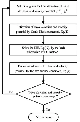
Fig.3 Calculation algorithm of the iterative time-marching method
2.3Wave exciting force analysis
The analysis of the wave exciting force is made in this section. The diffraction problem of a ship advancing at a constant forward speed,in an incident wave is simulated in the time domain. The Froude number is set to be equal to. The total simulation time isis the encounter period subjected to the incident waves.). The lasttime-history data, which are confirmed to be stable and periodical, are chosen to evaluate the wave exciting force. A Fourier-series expansion method used in He and Kashiwagi[7]is employed in the analysis of these time-history data.
In the numerical simulation, a wave height gauge travelling at the ship’s speed is put far ahead from the model to avoid the effect of the reflected waves by the hull. In the evaluation of the phase corresponding to the exciting force, the distance between the wave gauge and the model must be considered. The wave exciting forces,, shown in the following comparisons, denote the surge, heave, and pitch exciting forces, respectively.FxandFzarenondimensionalized by a factor ofis nondimensionalized by a factor of. Here,is the density of fluid,is the acceleration due to the gravity,is the amplitude of the incident wave,andare the breadth and the length of the ship, respectively.
3. Numerical results and discussions
In the seakeeping field, the ship-motion theory contains the following two major topics: the diffraction problem and the radiation problem. The radiation problem involves the analysis of hydrodynamic forces for a ship oscillating in a calm water, while the diffraction problem involves the study of wave exciting forces on a ship fixed in the incident waves. In the present paper, the wave diffraction problem is considered with three models with a forward speed under the linearized Neumann-Kelvin free-surface condition. For the stability of the simulation, the ship speed is gradually increased from zero to a specified constant value. The sensitivity to the computational domain size, the mesh size, and the time step was carefully investigated for the wave-making problem[5,15]and the diffraction problem[16]. The exciting forces on three models over a wide range of incident-wave frequencies are considered. The hull-form effects on the naval hydrodynamics are studied by comparing results obtained with these three models. Finally, the unsteady wave patterns and wave profiles generated by these models are compared to reveal the effects of the hull form.
3.1Ship models
The modified Wigley models are used, and they are defined by
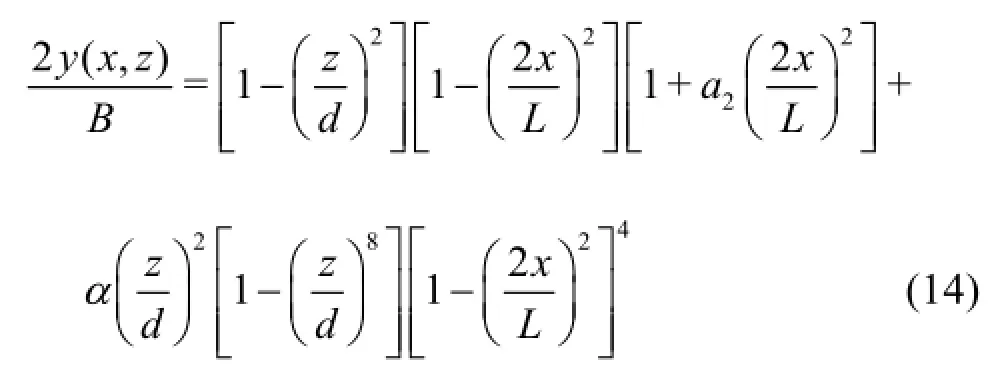
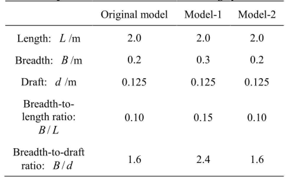
Table 1 Major dimensions of the modified Wigley models

Table 2 Hull-form parameters of the modified Wigley models
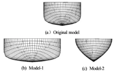
Fig.4 Meshes for three different modified Wigley models (front view)
As listed in Table 2, the hull-form parameters in Eq.(14) for Model-1 are kept the same as the original model. The only difference between Model-1 and the original model is the ship widthin Model-1 andin the original model. The major dimensions (length, width, and draft) of Model-2 and the original model are kept the same, with different hull-form coefficients,in Eq.(14). The coefficient is changed to make the hull-bottom of Model-2 much sharper, which can be clearly seen from Fig.4(c). The effect of the ship widthon the naval hydrodynamics is studied by comparing Model-1 with the original model, while the effect of the hull-form parameters on the naval hydrodynamics is studied by comparing Model-2 with the original model.
3.2Computational domain
A rectangular computational domain (see Fig.1)is truncated at some distance from the ship, and the damping beach is installed at the outer portion of the free surface except the downstream side. Convergence study is important in the validation of a numerical model, and it was performed systematically in He and Kashiwagi[5,16]. We have also checked the size of the damping beach carefully which is enough even for long waves. For saving computational time, only half domain is used for numerical computations, since the flow around a symmetric body is naturally symmetric about theplane.
In the present study, a typical computational domain is set asin therespectively. This was confirmed to be sufficient for the wave-making and diffraction simulations[5,16]. The grid on the free surface is uniform along thex-direction with its size of, while it is non-uniform along thedirection with an expansion ratiofrom the waterline to the end of the domain. Only half of the wetted hull surface is discretized with 51×11 nodes. Both body and free surfaces are discretized with 9-node quadrilateral panels described in Section 3.1. This typical meshis used for most of incident-wave frequencies in the diffraction calculations, while a finer mesh withis used for short waves at
For confirming the iterative time-marching scheme and the setting of the numerical model, the time history of iteration times against each time step is shown in Fig.5. From Fig.5, it can be found that the iterative time-marching scheme is efficient and the solution is stable.

Fig.5 Time history of iteration times against each time step at
3.3Wave exciting forces
To assess the performance of this numerical code, we simulate the unsteady diffraction problem for the above three modified Wigley models advancing at a constant forward speedinto a regular incident wave of amplitudeand circular frequencyand study the effects of the hull form on the naval hydrodynamics. Only the head wave is considered with an encounter frequency of. The ship speed is gradually increased from zero to a specified constant value,The hydrodynamic forces are plotted in the following figures in a nondimensional form. Time is nondimensionalized by a factor ofis the encounter period subjected to the incident waves. The time step is set as,
Comparisons of the nondimensional wave exciting forces between the original model and the modified models are shown in Fig.6 for the surge exciting force, in Fig.7 for the heave exciting force, and in Fig.8 for the pitch exciting moment, respectively. In these figures, the line with triangular points is the result for the original model, the line with rectangular points is for Model-1, and the line with circle points is for Model-2.
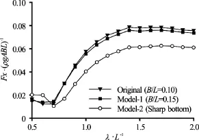
Fig.6 Comparison of surge exciting forces between modified models and original model with Froude number

Fig.7 Comparison of heave exciting forces between modified models and original model with Froude number0.2
From Figs.6-8, it can be seen that: (1) The discrepancy of the wave exciting forces among three different models is significant, especially, the surge exciting forces in Fig.6. (2) Numerical results become oscillating in the short waves, which can be considered as due to the insufficiency of panels. From a practical viewpoint, it is reasonable to pay attention mainly to moderate/long waves, since the excitingforces in range of short waves are relatively smaller than that in moderate/long waves.

Fig.8 Comparison of pitch exciting forces between modified models and original model with Froude number0.2
The effect of the ship width on the hydrodynamics forces is seen from the comparison between Model-1 and the original model, while the effect of the hull-form parameter is seen from the comparison between Model-2 and the original model. As mentioned before, the hull-form difference between Model-1 and the original model is only due to the ship widthThe width is set asfor the original model, andfor Model-1. From Fig.6, it can be seen that (1) the nondimensional surge exciting forces acting on Model-1 is slightly smaller than those on the original model. It should be noted that the absolute forces acting on Model-1 is larger than those on the original model, since the width of Model-1 is larger than that of the original model. Due to the nondimensional effect, in whichis nondimentionalized by a factor ofand other parameters, the surge exciting forces acting on Model-1 become smaller than those on the original model, (2) compared to the slight difference between Model-1 and the original model, the difference of the surge exciting forces between Model-2 and the original model is large due to the effect of the hull-form parameters. The original model has a plane bottom, while Model-2 has a sharp bottom. According to the present study, it can be found that the effect of the bottom-shape on the surge exciting forces is larger than the effect of the ship width
From Fig.7, it can be seen that the effects of the ship-width and the hull-form parameters on the heave exciting forceare clear. The effect of the shipwidth on the heave exciting forces (as shown by the results for the original model and Model-1 in Fig.7) is similar to that on the surge exciting forces. The effect of the bottom-shape of the ships can be found by comparing the results for Model-2 and the original model. Unlike the surge exciting forcethe heave exciting forceon Model-2 becomes larger than that on the original model, since the bottom-surface area acted by the heave exciting forces for Model-2 becomes larger, especially the part near the free surface. The pitch exciting forceis strongly related toandThe discussion ofwill not presented here, since the effects of the ship-width and the hullform parameters onare already discussed in detail.
Typical time histories of the wave exciting forces on the ship hulls are shown in Fig.9. As mentioned previously, the ship speed is accelerated from zero to a specified constant value. When the oscillation of the time-history data becomes stable and periodical, they are used for data analysis. It can be seen from Fig.9 that the oscillations of the exciting forces are indeed stable and periodical.

Fig.9 Time history of exciting forces on the original and modified models with
3.4Unsteady wave patterns and wave profiles
It is known that the hydrodynamic forces/pressure distribution on the hull is related to the wave pattern. To further understand the effects of the hull form on the naval hydrodynamics, the diffraction wave patterns generated by Model-1, Model-2 and the original model advancing at a forward speedin the head regular wave withare shown in Fig.10 and Fig.11 for comparison.

Fig.10 (Color online) Comparison of wave patterns generated by the original model and Model-1 advancing in regular head wave with

Fig.11 (Color online) Comparison of wave patterns generated by the original model and Model-2 advancing in regular head wave with
From Fig.10, it can be obviously seen that the amplitude of the diffraction wave generated by Model-1 is much larger than that generated by the original model, since the width of Model-1 is larger than that of the original model. The phases of the wave pattern between Model-1and the original model are very similar. In other words, a clear phase-shift of the wave pattern between Model-1 and the original model can not be found, since the hull-form parameters of these two models are the same.
It is known that the disturbed waves are much more affected by the shape of the hull near the free surface. From Fig.11, it can be seen that the amplitude of the diffraction wave generated by Model-2 is close to that of the original model, since they have the same shape of the waterline (the intersection of the ship hull and the still water surface). A phase difference between Model-2 and the original model can be seen around the ship hulls, especially near the amidships. Under the assumption of the linear theory, the socalledwave propagating in the downstream direction is known to have the same length of the incident wave (more details of thewave can be found in Kashiwagi and Iwashita[20]), which can be confirmed by both Fig.10 and Fig.11.
To compare the amplitude of the diffraction waves quantitatively, the wave profiles generated by the original model and the other modified models at a sectionare shown in Fig.12, which correspond to the wave patterns shown in Fig.10 and Fig.11. It is clear that the wave patterns generated by these three models are different and the amplitude of the waves generated by Model-1 is larger than those generated by the original model and Model-2.

Fig.12 Comparison of wave profiles generated by the original and modified models at a section ofwith
4. Conclusion
A time-domain iterative Rankine HOBEM for seakeeping analysis is proposed to predict the hydrodynamic characteristics for three different Wigley hulls. The ship waves generated by these three models advancing at a constant forward speed in waves and the resultant diffraction forces are calculated to reveal the hull-form effects on the naval hydrodynamics. The following conclusions can be drawn. (1) The effect of the hull-form parameter on the surge exciting forces is more sensitive than the effect of the ship width. The effects of the ship-width and the hull-form parameter on the heave exciting force are also clear. The heave exciting force on the model with a sharp bottom islarger than that on the model with a plane bottom. (2) The effect of the ship-width on the wave pattern is larger than the effect of the hull-form parameter. The phase shift in the wave patterns is mainly due to the difference of the hull form. It can be concluded that the proposed time-domain code can be used to investigate the hull-form effect on the hydrodynamics forces.
Acknowledgements
This work was supported by the the Open Research Fund Program of the State Key Laboratory of Satellite Ocean Environment Dynamics, Second Institute of Oceanography (Grant No. SOED1514), the State Key Laboratory of Coastal and Offshore Engineering, Dalian University of Technology (Grant No. LP1513) and the Key Laboratory of Water and Sediment Science and Water Hazard prevention, Changsha University of Science and Technology, (Grant No. 2015SS02).
[1] Yang C., Huang F. An overview of simulation-based hydrodynamic design of ship hull forms [J].Journal of Hydrodynamics, 2016, 28(6): 947-960.
[2] Lin W. M., Yue D. Numerical solution for large amplitude ship motions in the time domain [C].Proceedings of 18th Symposium on Naval Hydrodynamics, Michigan, USA, 1991, 41-66.
[3] Datta R., Sen D. A B-spline solver for the forward-speed diffraction problem of a floating body in the time domain [J].Applied Ocean Research, 2006, 28(2): 147-160.
[4] Kara F., Tang C., Vassalos D. Time domain three dimensional fully nonlinear computations of steady body-wave interaction problem [J].Ocean Engineering, 2007, 34(5-6): 776-789.
[5] He G., Kashiwagi M. Time-domain analysis of steady ship-wave problem using higher-order BEM [J].International Journal of Offshore and Polar Engineering, 2014, 24(1): 1-10.
[6] Yasukawa H. Application of a 3-D time domain panel method to ship seakeeping problems [C].Proceedings of Twenty-fourth Symposium on Naval Hydrodynamics, Fukuoka, Japan, 2003, 375-391.
[7] He G., Kashiwagi M. A time-domain higher-order boundary element method for 3D forward-speed radiation and diffraction problems [J].Journal of Marine Science and Technology, 2014, 19(2): 228-244.
[8] Kohansal A. R., Ghassemi H. A numerical modeling of hydrodynamic characteristics of various planning hull forms [J].Ocean Engineering, 2010, 37(5-6): 498-510.
[9] Kim Y., Kim K., Kim J. et al. Time-domain analysis of nonlinear motion responses and structural loads on ships and offshore structures: development of WISH programs [J].International Journal of Naval Architecture and Ocean Engineering, 2011, 3(1): 37-52.
[10] Bai W., Eatock Taylor R. Higher-order boundary element simulation of fully nonlinear wave radiation by oscillating vertical cylinders [J].Applied Ocean Research, 2006, 28(4): 247-265.
[11] Ning D. Z., Teng B. Numerical simulation of fully nonlinear irregular wave tank in three dimension [J].International Journal for Numerical Methods in Fluids, 2007, 53(12): 1847-1862.
[12] Gou Y., Chen X., Teng B. A time-domain boundary element method for wave diffraction in a two-layer fluid [J].Journal of Applied Mathematics, 2012, ID 686824.
[13] He G., Kashiwagi M., Hu C. Nonlinear solution for vibration of vertical elastic plate by initial elevation of free surface [J].International Journal of Offshore and Polar Engineering, 2010, 20(1): 34-40.
[14] Singh S. P., Sen D. A comparative linear and nonlinear ship motion study using 3-D time domain methods [J].Ocean Engineering, 2007, 34(13): 1863-1881.
[15] He G. An iterative Rankine BEM for wave-making analysis of submerged and surface-piercing bodies in finite water depth [J].Journal of Hydrodynamics, 2013, 25(6): 839-847.
[16] He G. An iterative Rankine boundary element method for wave diffraction of a ship with forward speed [J].Journal of Hydrodynamics, 2014, 26(5): 818-826.
[17] Suzuki K., Iokamori N. Studies on minimization of wave making resistance based on Rankine source method [J].Journal of the Society of Naval Architects of Japan, 1999, 185: 9-19(in Japanese).
[18] Saha G., Suzuki K., Kai H. Hydrodynamic optimization of ship hull forms in shallow water [J].Journal of Marine Science and Technology, 2004, 9(2): 51-62.
[19] He G., Kashiwagi M. Numerical analysis of the hydroelastic behavior of a vertical plate due to solitary waves [J].Journal of Marine Science and Technology, 2012, 17(2): 154-167.
[20] Kashiwagi M., Iwashita H. Ship motions [M]. Tokyo, Japan: Seizando Press, 2012.
(Received January 15, 2014, Revised July 28, 2015)
* Project supported by the National Natural Science Foundation of China (Grant Nos. 51579058, 11502059), the Shandong Provincial Natural Science Foundation (Grant No. ZR2014EEQ016).
Biography: Guang-hua He (1980-), Male, Ph. D., Professor
杂志排行
水动力学研究与进展 B辑的其它文章
- Magnetohydrodynamic flows tuning in a conduit with multiple channels under a magnetic field applied perpendicular to the plane of flow*
- Comparison of blood rheological models in patient specific cardiovascular system simulations*
- The best hydraulic section of horizontal-bottomed parabolic channel section*
- Numerical simulation of hydrodynamic performance of blade position-variable hydraulic turbine*
- The effects of step inclination and air injection on the water flow in a stepped spillway: A numerical study*
- Efficient suction control of unsteadiness of turbulent wing-plate junction flows*
