A Study on the Far Wake of Elliptic Cylinders
2017-03-13SubhankarSenandSanjayMittal
Subhankar Sen and Sanjay Mittal
1 Introduction
Most studies concerning external flow past two-dimensional bluff bodies concentrate on regions immediately downstream of the body while the far wake is of no less physical and practical significance. The practical application of far wake analysis includes the non-acoustic detection of submarines near thermoclines (Vorobieff et al., 2002). As an outcome of diffusion and viscous dissipation of Karman vortices, the vortex street might be expected to disappear in far downstream (Zdravkovich, 1997). For flow past a circular cylinder for Reynolds number, Re<200, (Tritton, 1977) commented that `the vortex street continues to all distances downstream'. As pointed out by Cimbala et al. (1988) earlier,this statement deems invalid as the flow characteristics in the near (small multiple of characteristic dimension) and far (large multiple of characteristic dimension) wake vary drastically. The pioneering experimental work of Taneda (1959) demonstrated the formation of `secondary vortex street' in the far wake, where the scales of vortical structures are multiples of those in the primary or Karman vortex street. The wake transition in general, can occur in any staggered vortex street (Vorobieff et al., 2002).With downstream distance, the spatial transition of the wake obeys the following sequence: primary or Karman vortex street → nearly parallel shear layers → secondary vortex street.
Developments in the wake of two-dimensional symmetric bluff bodies (eg. circular,elliptic cylinders and vertical flat plate) with Re have been studied earlier by several researchers. These studies, in general, do not consider the effect of blockage, B on the wake state. Blockage is the ratio of cross-stream projection of the body and width of the experimental apparatus or computational domain. In the present work, we study the evolution of far wake of elliptic cylinders with angle of attack, α while Re is fixed. The effect of channel confinement on the development of secondary vortex street is also studied. Geometry of an ellipse is characterized by its aspect ratio, AR defined as the ratio of lengths of its minor and major axes denoted by b and a, respectively. Two extreme configurations of an ellipse are the flat plate (AR = 0) and circular cylinder (AR = 1). A review on the earlier studies on unsteady flow past stationary elliptic cylinders and evolution of far wake with Re for various symmetric bluff bodies is provided below.
Lugt and Haussling (1974) presented results at Re = 15, 30 and 200 for the flow past elliptic cylinders of AR = 0.1 and 0.2 at 450incidence. They employed finite-difference to discretize the unsteady streamfunction-vorticity (ψ-ω) equations. Patel (1981) followed a semi-analytical method for the unsteady ψ-ω equations. For impulsively started elliptic cylinders of various eccentricities and α between 00and 900, he presented detailed results at Re = 60, 100 and 200. Based on numerical study, Park et al. (1989) identified for 25≤Re≤600, various flow regimes for an elliptic cylinder of AR≈0.15. For elliptic cylinders with major axes oriented normal to the incoming stream, Johnson et al. (2001)studied the evolution of wake vortex structures with Re and AR. The parameter space for the numerical study was 30≤Re≤200 and 0.01≤AR≤1. At constant Re, a monotonic increase of the drag coefficient with decreasing AR was noted. For symmetric elliptic cylinders of AR = 0.6, 0.8, 1.0 and 1.2, Kim and Sengupta (2005) presented numerical results highlighting the effects of Re and AR on various integral parameters, such as the aerodynamic coefficients and shedding frequency. The Reynolds numbers studied were 200, 400 and 1000. Experiments at high Re were conducted by Taneda (1972), Modi and Dixit (1975), Ota and Nishiyama (1986) and Ota et al. (1987). Numerical investigations in the high Re regime include those of Panikker and Lavan (1975), Mittal and Balachandar (1996), Badr et al. (2001) and Li et al. (2006). The initial separation of laminar boundary layer for elliptic cylinders of various thicknesses and orientations have been numerically investigated by Sen et al. (2012). They proposed the wake topology for inclined elliptic cylinders and also explored the relationship between separation Reynolds number and angle of incidence.
Following flow visualization in water tank, Taneda (1959) first observed for a circular cylinder and flat plate, downstream decay of the primary or Karman vortex street and further downstream, eventual formation of the secondary vortex street. Taneda (1959)conjectured that the formation of secondary vortex street is an outcome of changing hydrodynamic stability. By artificially decelerating the Karman street of a circular cylinder, Durgin and Karlsson (1971) demonstrated that the formation of a new(secondary) vortex street is preceded by the deformation and streamwise alignment of primary vortices to form shear layers (referred to as `calm region' by them). An alternate mechanism leading to the formation of secondary vortex street was proposed by Matsui and Okude (1981) who suggested that pairing of Karman vortices rather than hydrodynamic instability of the wake profile leads to the formation of large scale vortices.Based on experimental investigation (flow visualization and hot-wire anemometry) of near and far wakes of two-dimensional bluff bodies, Cimbala et al. (1988) concluded that the far wake structures originate from hydrodynamic instability of the developing mean wake profile. The scale or frequency of the Karman vortices does not affect these large structures. The experimental work of Williamson and Prasad (1993a,b) shows that the far wake structures are sensitive to free-stream disturbances, they originate from hydrodynamic instability and in contrast to the observations made by Cimbala et al.(1988), the far wake frequency is closely linked to the near wake frequency through the frequency of free-stream disturbances. For Re between 70 and 154, Karasudani and Funakoshi (1994) experimentally investigated the breakdown and rearrangement of the primary vortex street of a circular cylinder.
For a zero-thickness flat plate oriented normal to the flow, Najjar and Balachandar (1998)numerically investigated at Re = 250, the origin of low frequency (roughly one-tenth of Karman frequency) unsteadiness present in the wake and its effects on the Karman frequency, drag and lift amplitudes. Based on numerical flow visualization, they conjectured that a lack of synchronization between the streamwise and spanwise vortices in the wake leads to the low frequency unsteadiness. Inoue and Yamazaki (1999) studied numerically both the unforced and sub-harmonic (of shedding frequency) forced far wakes of a circular cylinder for 140≤Re≤1000. While the mechanism involving merger of Karman vortices played a key role in forced wake transition, no clear evidence was found that this mechanism also leads to unforced wake transition. For an elliptic cylinder of AR= 0.5 with α = 900, Johnson et al. (2001) identified six different wake patterns for 30≤Re≤250. The study indicates that the transition Re for the onset of shedding in far wake is associated with a peak in the Strouhal number and a minimum in the drag coefficient. In a subsequent numerical investigation, Johnson et al. (2004) demonstrated that the frequency of the secondary structures is not a multiple of the primary frequency and hence argued that the secondary structures arise out of an instability in the mean velocity profile. The two-dimensional numerical simulations and experiments conducted by Vorobieff et al. (2002) for Re<1000 show that the streamwise distance for the onset of second wake measured from a circular cylinder decays as Re-1/2. Saha (2007) investigated the developments with Re in the far wake of a vertical flat plate of AR = 0.125. The finitedifference based two-dimensional analysis of Saha (2007) for Re = 30-175, identified various frequencies and also demonstrated that the steady far wake undergoes unsteady transition at Re = 145 marked by the presence of large scale vortical structures. Kumar and Mittal (2012) employed direct numerical simulations as well as global linear stability analysis to investigate the origin of secondary vortex street in the far wake of a circular cylinder at Re = 150. They identified the streamwise location of the dominant modes in the wake that lead to the formation of secondary vortex street. They concluded that the far wake structures arise out of a convective instability. The study demonstrates that suppression of primary vortex street via a slip splitter plate placed suitably, can also suppress the large scale structures in far wake.
For elliptic cylinders of AR = 0.2, 0.5 and 0.8, we report in the paper, results demonstrating the transitions in the far wake as function of α. For a fixed Re of 200, α varies between 00and 900, in steps of 150. The present numerical investigation also explores the dependence of integral parameters on cylinder thickness and α. The effect of blockage (B = 0.20) on the development of secondary vortex street is studied for the AR =0.2, α = 900configuration. A stabilized Petrov Galerkin finite-element method using equal order bilinear interpolation for velocity and pressure is employed.
2 The governing equations

Here u = (u, v), f and σ denote the fluid velocity, body force per unit volume and the Cauchy stress tensor, respectively. The stress is the sum of its isotropic and deviatoric parts:

where p, I, μ and σ are the pressure, identity tensor, dynamic viscosity of the fluid and strain rate tensor, respectively. Both, the Dirichlet and Neumann-type boundary conditions are accounted for and are represented as

respectively, where Γgand Γhare complementary subsets of the boundary Γ, n is its unit normal vector and h is the surface traction vector. In the present simulations concerning low blockage, we have employed the towing tank boundary condition (see Figure 1a) on the lateral walls of the domain. This involves free-stream speed condition on the upstream as well as lateral boundaries. No-slip boundary condition is applied on the surface of the cylinder. At the downstream boundary, a Neumann condition for velocity is specified that corresponds to stress-free condition. For high blockage, the inlet flow is fully developed and sidewalls represent no-slip boundaries.
The initial condition on the velocity is specified on Ω at t = 0: u(x,0)= u0on Ω,
where u0is divergence-free, i.e. u0satisfies Equation (2).
3 The finite-element formulation
The spatial domain Ω is discretized into non-overlapping subdomains Ωe, e =1,2, ..., nelwhere nelis the number of elements. Letandbe the finite dimensional trial function spaces for velocity and pressure, respectively and the corresponding weighting function spaces are denoted byand. The stabilized finite-element formulation of the conservation Equations (1) and (2) is written as follows:
而秋瑾与王廷均是包办婚姻。这个婚姻不可谓不门当户对,一个是厘金局总办千金,一个是湘潭首富之子。婚姻初期,诗词唱和,生活安逸。但此后由于思想的差距,二人渐行渐远。王廷均是不是深爱着秋瑾因没有情书书信流传不得而知,但是对秋瑾一直不离不弃,赴京捐官,也是因为秋瑾由此建议。直至后期秋瑾只身留学,王却带着两个幼子回到乡中。而且坚持不与秋瑾离婚,并在秋瑾死后两个月,积郁而死。这两颗越来越远的心,昭示着有一个包办婚姻的悲剧。
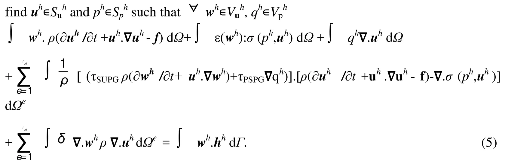
In the variational formulation given by Equation 5, the first three terms and the right hand side constitute the Galerkin formulation of the problem. The first series of element level integrals are the SUPG (streamline-upwind/Petrov-Galerkin) and the PSPG (pressurestabilizing/Petrov-Galerkin) stabilization terms added to the variational formulations of the momentum and the continuity equations, respectively. At high Re, in an advection dominated flow, Galerkin formulation of the flow equations lead to oscillations in the velocity field. This numerical instability is overcome by adding SUPG stabilization terms.The SUPG formulation for convection dominated flows was introduced by Hughes and Brooks (1979) and Brooks and Hughes (1982). PSPG stabilization terms are added to the formulation to enable the use of equal order interpolation for velocity and pressure.Hughes et al. (1986) introduced the pressure stabilization methods in the context of Stokes flow and Tezduyar et al. (1992) generalized the method to flows at finite Re. More details of the finite-element formulation can be found in Tezduyar et al. (1992).
4 Problem set-up

Figure 1: Re = 200 unsteady flow past elliptic cylinders: (a) problem definition for the unbounded case. Positive sign convention for the aerodynamic forces and moment is shown in (b). The moment is calculated about the center of the cylinder.
The problem statement for unbounded flow past an elliptic cylinder is shown in Figure 1a.The center of the cylinder coincides with the origin of the Cartesian coordinate system.The angle of attack is measured clockwise with respect to the direction of incoming flow.To simulate unbounded flow, the domain width, H is fixed at 100a (thus, B = 0.01 for α =900and B<0.01 for other values of α) and the towing tank condition is used at the sidewalls of the domain. The Reynolds number and Strouhal number, St are based on a and free-stream speed, U. For confined flow (B = 0.20), the velocity is set to zero at the sidewalls and a parabolic velocity profile is specified at the inlet: u = 1-(2y/H)2, v = 0. Re and St for this flow are based on the centerline speed. For all the computations, distances of the upstream and downstream boundaries measured from the center of the cylinder are Lu= 45a and Ld= 80a, respectively. Figure 1b illustrates the positive sign convention for the aerodynamic forces and moment. The instantaneous force (Cd, Cl) and moment (Cm)coefficients are defined as

Here nxand nyare the x and y components, respectively of the unit vector n normal to the cylinder boundary Γcyland r is the radius vector of any arbitrary point located on the cylinder surface measured from the center of cylinder.
5 The finite-element mesh
For a representative AR of 0.5 and α of 450, Figure 2 shows the non-uniform finiteelement mesh consisting of bilinear quadrilateral elements and its close-up near the cylinder. The number of nodes and elements are 107976 and 107168, respectively and remains constant for all the meshes used. The mesh has been constructed by combining five blocks; a central square block containing the cylinder and four neighbouring rectangular blocks located to the left, right, top and bottom of the central block. To efficiently resolve the secondary structures in the far wake, a sufficiently fine mesh is designed for the right side rectangular block. This block contains 18954 nodes and 18792 elements. For every mesh, the number of nodes on the cylinder, Ntis kept constant at 464 and radial thickness of the first layer of elements located on the cylinder,0.0005a.

Figure 2: Unsteady flow past elliptic cylinders: (a) the non-uniform finite-element mesh for a 450 inclined elliptic cylinder of AR = 0.5 and (b) close-up of the central square block containing the cylinder. The mesh contains 107976 nodes and 107168 bilinear quadrilateral elements.
6 Validation of method and convergence of results
6.1 Comparison with the earlier studies
In order to ascertain validity of the computed results, predicted time-averaged drag coefficient,and vortex shedding frequency of elliptic cylinders of AR = 0.25 and 0.5 for α = 900are compared with those obtained by Johnson et al. (2001) at Re = 175 and 200, respectively (see Table 1). The comparison in general reveals satisfactory agreement(the maximum difference is about 5% forat Re = 200) between the two sets of results.
Table 1: Unsteady flow past elliptic cylinders of various AR with major axis oriented normal to the flow: comparison of the predicted and St with those obtained by Johnson et al. (2001).
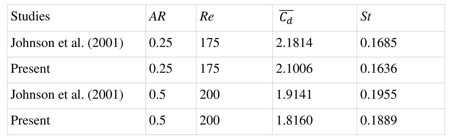
Table 1: Unsteady flow past elliptic cylinders of various AR with major axis oriented normal to the flow: comparison of the predicted and St with those obtained by Johnson et al. (2001).
?
Detailed validation of computed results for unsteady flow past stationary elliptic cylinders has been recently discussed in Sourav and Sen (2017).
6.2 Effect of spatial resolution
To establish mesh independence of the computed results, the flow past a 450inclined elliptic cylinder of AR= 0.2 is computed at Re = 200 on several meshes. Out of the many meshes, information on meshes M1 and M2 are listed in Table 2. The number of nodes and elements of M2 is roughly twice the ones used for M1. The non-dimensional time step size, ΔtU/a for the computations is 0.005. The results summarized in Table 2 indicate that the spatial resolution of M1 is sufficient to accurately predict the unsteady flow past elliptic cylinders.
Table 2: Flow past an elliptic cylinder of AR= 0.2 at α = 450: effect of mesh resolution on the flow characteristics at Re = 200. The other parameters for this study are: Lu = 45a, Ld= 80a, = 0.0005a and ΔtU/a = 0.005. For M1, Nt = 464 and for M2, Nt = 672. The subscript r.m.s. implies root mean square of a quantity.
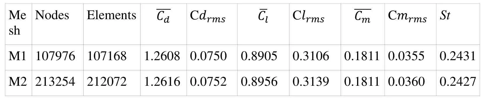
Table 2: Flow past an elliptic cylinder of AR= 0.2 at α = 450: effect of mesh resolution on the flow characteristics at Re = 200. The other parameters for this study are: Lu = 45a, Ld= 80a, = 0.0005a and ΔtU/a = 0.005. For M1, Nt = 464 and for M2, Nt = 672. The subscript r.m.s. implies root mean square of a quantity.
?
6.3 Effect of time step size
To examine the effect of time step size on the flow characteristics, the Re = 200 flow past a 450inclined elliptic cylinder of AR = 0.2 is computed on mesh M1 using ΔtU/a = 0.005 and 0.0025. Table 3 summarizes the results and establishes the adequacy of ΔtU/a =0.005 for the present computations. Based on the spatial and temporal resolution tests, all computations in the present work are performed on mesh M1 using ΔtU/a = 0.005.
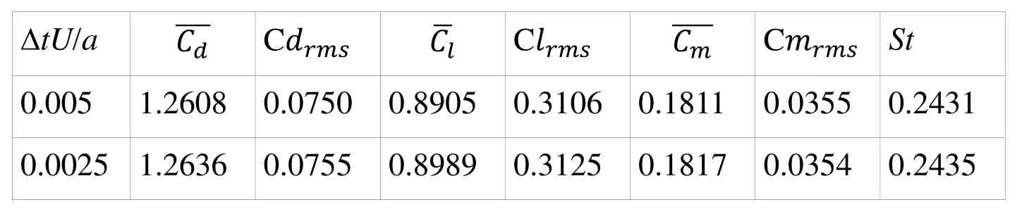
Table 3: Flow past an elliptic cylinder of AR = 0.2 at α = 450: effect of time step size on the flow characteristics at Re = 200. The computations are carried out on Mesh M1.
7 Results
Results are presented for unsteady flow at Re = 200 past elliptic cylinders of aspect ratios 0.2, 0.5 and 0.8 as well as angles of attack between 00and 900. Each numerical computation uses the corresponding steady flow solution at Re = 40 as the initial condition. The linearized algebraic equation system has been solved by GMRES or Generalized Minimal RESidual method (Saad and Schultz, 1986) in conjunction with a diagonal preconditioner.
7.1 Flow characteristics: the integral parameters
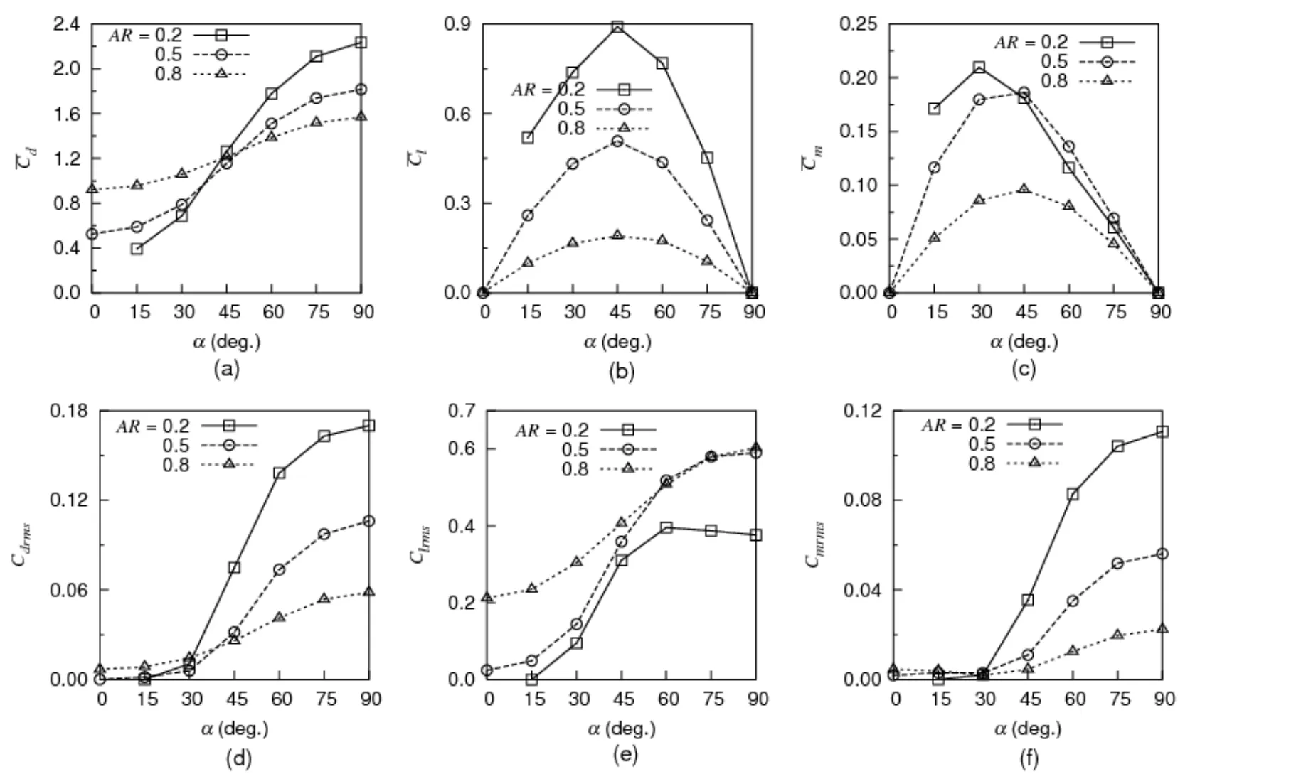
Figure 3: Re = 200 unsteady flow past elliptic cylinders of AR = 0.2-0.8: variation of the time-averaged (first row) and r.m.s. (second row) values of aerodynamic coefficients with α.
For any orientation of an elliptic cylinder, amplitude of lift oscillation is the largest while moment oscillates with the smallest amplitude (Sen, 2010). Thus, relative amplitudes of the aerodynamic coefficients suggest Clrms> Cdrms, Cmrms. Figures 3(a,d) indicate that the time-averaged and r.m.s. drag of elliptic cylinders continue to increase with increasing α and attain the maxima when α = 900. For α≥600,and Cdrmsincrease with decreasing AR. As seen from Figure 3b,of each cylinder initially increases with increasing α and then decreases. The average lift and moment vanish for symmetric configurations of α = 00and 900. When α is fixed, the lift generated by a cylinder increases with decreasing thickness. Figure 3e demonstrates that Clrmsfor AR = 0.2 displays a non-monotonic variation with α. Interestingly, a monotonic rise is seen for AR≥0.5. With α,of each cylinder displays non-monotonic variation (Figure 3c) and r.m.s. moment coefficient, Cmrmsdisplays monotonic rise (Figure 3f) for α≥300.
To analyze the primary vortex shedding characteristics, Fast Fourier Transform (FFT) is performed on the signals of aerodynamic coefficients. For each AR and α, the lift and moment coefficients are found to oscillate at the primary vortex shedding or Strouhal frequency. The drag coefficient in general, oscillates at twice the primary frequency.Exceptions to this are found for AR≤0.5 at low α. When α≤450, FFTs of Cdand Clfor AR= 0.2 lead to the same value of St. The power spectra of Cdand Clfor AR = 0.2, α = 450reveal three and two distinct peaks, respectively (Figures 4a and 4b). The dominant peak of each spectrum corresponds to the same frequency (St = 0.2431) and the drag-lift phase diagram consists of a single loop (Figure 4c). For AR = 0.5, values of St obtained from FFTs of Cdand Clconverge when α ≤300. Figures 4(d,e) illustrate for AR = 0.5 and α =900, the power spectra of Cdand Cl. For this case, the drag oscillates at twice the shedding frequency. Phase diagram for this configuration (Figure 4f) is of the shape of a distorted figure eight characterized by the presence of a cross-over point. Phase diagrams of Figures 4(c,f) are closed and ascertain periodic nature of flow. Dominance of the amplitude of lift over drag is also apparent from these plots.

Figure 4: Unsteady flow past elliptic cylinders at Re = 200: non-dimensional power spectra of the (a) drag, (b) lift coefficients and (c) the drag-lift phase diagram for AR =0.2, α = 450. Figures (d), (e) and (f) respectively plot the same quantities for AR = 0.5 and α = 900.
Figure 5a indicates that St of an elliptic cylinder decays monotonically with increasing α.St of a thick cylinder (AR = 0.8) is relatively less sensitive to α. The decaying trend of St with α is opposite to the one observed for a square cylinder. Slow monotonic growth of St with increasing α was reported by Sohankar et al. (1998) for a square cylinder with 00≤α≤450. For α≤450, St decreases monotonically with decreasing AR. The trend reverses for α≥750. The predicted vortex shedding frequencies are in close agreement (maximum deviation being 2.26%) with those obtained by Sheard (2007) for AR = 0.5, α = 150and 300. The intervortex spacing along each row of the vortex street or primary wavelength,a1is inversely proportional to the local St. In particular, a1/a = 1/St (Vorobieff et al.,2002). Figure 5b suggests monotonic growth of a1/a with increasing α. a1/a of a cylinder attains the maximum when α = 900.

Figure 5: Re = 200 unsteady flow past elliptic cylinders of AR = 0.2-0.8 in the unbounded medium: variation of (a) Strouhal number and (b) primary wavelength, a1/a with α.
7.2 The evolution of wake with α
We study the wake transition for a thin cylinder (AR = 0.2). To identify various frequencies, time histories of cross-flow component of velocity are recorded at sixteen locations in the wake along the x axis. The velocity probes are located at approximate downstream distances of 2a, 6a, 10a, 15a, 20a, 25a, 30a, 35a, 40a,45a, 50a, 55a, 60a, 65a, 70a and 75a, respectively measured from the cylinder center.To resolve the frequencies, about 218data points are used for performing FFT of the cross-flow component of velocity.
7.2.1 The instantaneous vorticity field
Figure 6 shows that the flow is steady and vortex shedding is absent at low α, such as 00and 150. The flow becomes unsteady at some critical α between 150and 300and Karman vortex shedding from the cylinder ensues. When α = 300, the wake is comprised of two parts. The first part close to the cylinder is the Karman vortex street where the alternately shed vortices appear as concentric circles. In the second part, the vortices are deformed to elliptical cross-section and orient themselves with major axes parallel to the free-stream as observed by Durgin and Karlsson (1971). The mechanisms leading to the deformation of Karman vortices were explained by Durgin and Karlsson (1971) and later, Karasudani and Funakoshi (1994). These deformed vortices form two parallel and opposite signed shear layers on either side of the wake centerline that extend downstream and appear not to interact mutually. A markedly different wake pattern is observed as α approaches 450.The shear layers become unstable, begin mutual interaction and terminate well ahead of the domain exit. Also, width of individual shear layers increase relative to the width at α= 300. The secondary vortex street characterized by large scale vortical structures, width and wavelength than the primary, is seen to develop at x ≈ 50a.
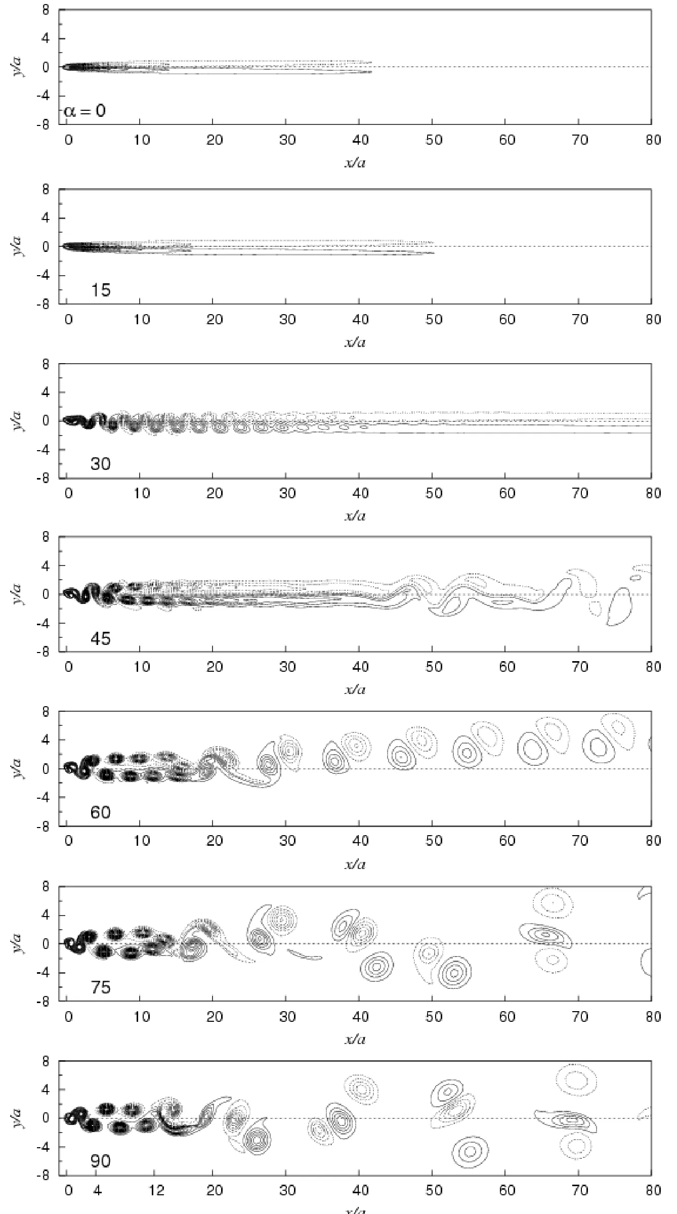
Figure 6: Re = 200 unsteady flow past an elliptic cylinder of AR = 0.2 in an unbounded medium: instantaneous vorticity field for various values of α between 00 and 900.
Rapid decay of the streamwise extent of the shear layers is observed for α = 600. The far wake vorticity distribution for this configuration is characterized by the one-sided convection of the secondary vortex pairs (comprising of vortices of opposite signs) away from the x axis. With increasing α, breakdown of the primary vortex street occurs closer to the cylinder. The shear layers gradually shrink in streamwise extent and attain the minimum when α = 900. Consequently, the location of formation of secondary vortex street moves upstream. For α ≥750, the secondary vortices interact strongly with each other and group of three vortices form with two of them having the same sign. It is shown in Section 7.2.2 that a tertiary frequency of low magnitude appears in the far downstream for α≥750. When α = 900, the secondary structures are visible sufficiently close to the cylinder, the distance being of the order of 20a. The developments in the wake with α for a fixed Re appear analogous to the cases of transition of wake with Re for a cylinder of fixed orientation (Johnson et al., 2001; Johnson et al., 2004; Saha, 2007). Though not shown here, it is found that the location of formation of secondary vortices moves far downstream with increasing AR.
7.2.2 The frequency distribution
For α = 00and 150, the flow is steady and vortex-shedding frequency is absent. The transverse velocity component for α = 300is time periodic in the near wake and the fluctuations diminish at large distance downstream implying steady nature of the far wake (Figure 7a). The coexistence of unsteady near wake and steady far wake was earlier pointed out by Saha (2007) for the flow past a vertical flat plate at Re = 100. The wake state for α = 300is characterized by the primary frequency alone. This is evident from Figure 7b which also demonstrates the weakening and eventual disappearance of the shedding frequency in the far wake.

Figure 7: Re = 200 unsteady flow past a 300 inclined elliptic cylinder of AR = 0.2 in an unbounded medium: (a) time series of v velocity signals at x/a = 2 and 75, (b) normalized power spectra of v velocity at selected downstream locations along the x axis.
Figure 8 shows for α = 450and 600, frequency characteristics at selected downstream locations. The secondary frequency first appears at α = 450and when α is increased to 600,this frequency is realized relatively close to the cylinder. At the location of probes, Figure 9 shows the power spectra of cross-flow component of velocity for α = 750. Associated with α≥750are several additional frequencies. The most prominent among them is the low magnitude tertiary frequency that appears in the far wake. The tertiary frequency becomes the most dominant for x≥60a.
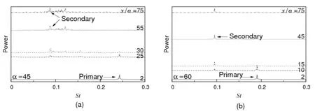
Figure 8: Re = 200 unsteady flow past an inclined elliptic cylinder of AR = 0.2 in an unbounded medium: normalized power spectra of v velocity at various downstream locations for α = (a) 450 and (b) 600.
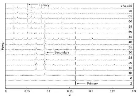
Figure 9: Re = 200 unsteady flow past a 750 inclined elliptic cylinder of AR = 0.2 in an unbounded medium: normalized power spectra of v velocity at various downstream locations.
It is found that the values of primary shedding frequency obtained by performing FFTs of the time series of Cland v are in excellent agreement. Values of various frequencies present in the wake are listed in Table 4. The primary frequency of a cylinder has the largest magnitude and the magnitude of tertiary frequency, if it exists, is the smallest. The secondary frequency has a magnitude intermediate to the ones for primary and tertiary. A non-monotonic variation of the secondary frequency with α is apparent from the table. In contrast, the primary frequency exhibits monotonic decrease with increasing α (also see Figure 5a). It is also evident from the table that the primary frequency is not a multiple of the secondary for α = 450, 750and 900. Interestingly, for α = 600, the secondary frequency is a sub-harmonic of the primary. The primary frequency in most cases is not a multiple of the secondary frequency suggesting that the secondary vortices do not form out of interaction of the shed primary vortices (also see Karasudani and Funakoshi (1994) and Johnson et al. (2004)). The distribution of dominant frequencies is shown in Figure 10 for 300≤α≤900. Among the primary, secondary and tertiary frequencies, secondary frequency exhibits the least sensitivity to α.

Table 4: Flow past an elliptic cylinder of AR = 0.2 for α = 300-900: summary of various frequencies present in the wake at Re = 200.
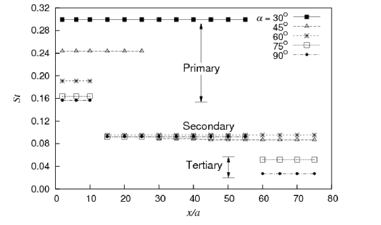
Figure 10: Re = 200 unsteady flow past an elliptic cylinder of AR = 0.2 in unbounded medium: distribution of dominant frequencies along the wake centerline for 300≤α≤900.
7.3 Effect of blockage on the far wake
We next investigate the effect of channel confinement on the wake structures of the AR =0.2 cylinder at Re = 200. To meet this objective, a blockage of 0.20 is used (see Section 4). FFT of cross-flow component of velocity measured at all the sixteen probes leads to the same value of primary frequency (St = 0.2232). This value is significantly higher than the one for unbounded flow (St = 0.1569 from Table 4).As apparent from Figure 11, the primary frequency prevails over all locations along the wake centerline and the wake state is characterized by the absence of any other significant frequency. The immediate effect of blockage is therefore to suppress the formation of secondary vortex street. Absence of secondary vortices in the far wake is also evident from Figure 12 showing the instantaneous vorticity field.

Figure 11: Confined flow (B = 0.20) past a perpendicularly oriented elliptic cylinder of AR = 0.2 at Re = 200: frequency distribution at various locations along the x axis.

Figure 12: Instantaneous vorticity field at Re = 200 for the confined flow past an elliptic cylinder of AR = 0.2 and α = 900. For this figure, Ld = 80a and B = 0.20.
In order to investigate if the imposition of blockage pushes the onset of secondary wake further downstream, computations are performed by doubling Ld, i.e. Ld= 160a while other parameters remain unaltered. Apart from the previously employed sixteen velocity probes, eleven more are placed along the wake centerline at approximate downstream distances of 82.5a, 90a, 97.5a, 105a, 112.5a, 120a, 127.5a, 135a, 142.5a, 150a and 157.5a measured from the cylinder center. The frequency spectra presented in Figure 13 for certain streamwise locations along the x axis, demonstrate monofrequency (St =0.2232) nature of the wake and establish that imposition of blockage can suppress the formation of secondary vortices.

Figure 13: Confined flow past a perpendicularly oriented elliptic cylinder of AR = 0.2 at Re = 200: normalized power spectra of cross-flow component of velocity component at various locations along the x axis. For this figure, Ld = 160a and B = 0.20.
8 Conclusions
The transition of wake of elliptic cylinders with varying angle of attack (00≤α≤900) is investigated using a stabilized finite-element method. Results are presented for twodimensional simulations at Re = 200. Stationary elliptic cylinders of aspect ratios 0.2, 0.5 and 0.8 are considered. For each AR and α, the lift coefficient oscillates with the largest amplitude. The smallest amplitude oscillations are in general associated with moment coefficient. The r.m.s. value of lift exceeds the ones for drag and moment. Irrespective of AR, the time-averaged and r.m.s. drag increase monotonically with increasing α. In contrast, the time-averaged lift and moment initially increase and then decrease. With increasing α, the primary shedding frequency of each cylinder continues to decay and the primary wavelength exhibits a reverse trend. In general, the shedding frequency obtained via FFT of lift is half the value obtained from FFT of drag. Interestingly, both FFTs lead to the same frequency for AR≤0.5 at low α. For AR = 0.2, the flow is steady for α = 00and 150. An unsteady wake characterized by Karman vortices and associated primary frequency, is seen as α increases to 300. The large scale secondary structures appear first when α = 450. The secondary frequency is also captured first at this incidence angle. For α≥750, analysis of power spectra shows the existence of a low magnitude tertiary frequency in the far wake. Compared to the primary and tertiary counterparts, secondary frequency displays lesser sensitivity to α. For most of the angles of attack studied, the secondary frequency is not a sub-harmonic of primary, signifying that the secondary structures do not form due to coalescence of primary vortices. For each AR, the location of formation of secondary structures moves upstream with increasing angle of attack.When α is fixed, similar behaviour is observed with decreasing cylinder thickness. For confined flow, the instantaneous vorticity field and power spectra of transverse velocity suggest that blockage suppresses the formation of secondary vortices.
Badr, H. M., Dennis, S. C. R. and Kocabiyik, S., (2001). Numerical simulation of the unsteady flow over an elliptic cylinder at different orientations. Int. J. Num. Meth. Fluids,vol. 37, pp. 905-931.
Brooks, A. N. and Hughes, T. J. R., (1982). Streamline upwind/Petrov-Galerkin formulations for convection dominated flows with particular emphasis on the incompressible Navier-Stokes equations. Comput. Methods Appl. Mech. Eng., vol. 32, pp.199-259.
Cimbala, J. M., Nagib, H. M. and Roshko, A, (1988). Large structure in the far wakes of two-dimensional bluff bodies. J. Fluid Mech., vol. 190, pp. 265-298.
Durgin, W. W. and Karlsson, S. K. F., (1971). On the phenomenon of vortex street breakdown. J. Fluid Mech., vol. 48, pp. 507-527.
Hughes, T. J. R. and Brooks, A. N., (1979). A multi-dimensional upwind scheme with no crosswind diffusion. Finite Element Methods for Convection Dominated Flows (ed. T.J. R. Hughes), vol. 47, pp. 19-35.
Hughes, T. J. R., Franca, L. P. and Balestra, M., (1986). A new finite element formulation for computational fluid dynamics: V. Circumventing the Babuska-Brezzi condition: A stable Petrov-Galerkin formulation of the Stokes problem accommodating equal-order interpolations. Comput. Methods Appl. Mech. Eng., vol. 59, pp. 85-99.
Inoue, O. and Yamazaki, T., (1999). Secondary vortex streets in two-dimensional cylinder wakes. Fluid Dyn. Res., vol. 25, pp. 1-18.
Johnson, S. A., Thompson, M. C. and Hourigan, K., (2001). Flow past elliptical cylinders at low Reynolds numbers. In Proc. 14thAustralasian Fluid Mechanics Conference, Adelaide, pp. 343-346.
Johnson, S. A., Thompson, M. C. and Hourigan, K., (2004). Predicted low frequency structures in the wake of elliptical cylinders. European J. Mech. B Fluids, vol. 23, pp.229-239.
Karasudani, T. and Funakoshi, M., (1994). Evolution of a vortex street in the far wake of a cylinder. Fluid Dyn. Res., vol. 14, pp. 331-352.
Kim, M. S. and Sengupta, A., (2005). Unsteady viscous flow over elliptic cylinders at various thickness with different Reynolds numbers. J. Mech. Sci. Tech. (KSME Int. J.),vol. 19, pp. 877-886.
Kumar, B. and Mittal, S., (2012). On the origin of the secondary vortex street. J. Fluid Mech., vol. 711, pp. 641-666.
Li, Z., Davidson, J. H. and Mantell, S., (2006). Numerical simulation of flow field and heat transfer of streamlined cylinders in cross flow. Trans. ASME: J. Fluids Eng., vol. 128,pp. 564-570.
Lugt, H. J. and Haussling, H. J.,(1974). Laminar flow past an abruptly accelerated elliptic cylinder at 450incidence. J. Fluid Mech., vol. 65, pp. 711-734.
Matsui, T. and Okude, M., (1981). Vortex pairing in a Karman vortex street. In Proc.Seventh Biennial Symp. Turbulence.
Mittal, R. and Balachandar, S., (1996). Direct numerical simulation of flow past elliptic cylinders. J. Comput. Phys., vol. 124, pp. 351-367.
Modi, V. J. and Dikshit, A. K., (1975). Near-wakes of elliptic cylinders in subcritical flow. AIAA J., vol. 13, pp. 490-497.
Najjar, F. M. and Balachandar, S., (1998). Low-frequency unsteadiness in the wake of a normal flat plate. J. Fluid Mech., vol. 370, pp. 101-147.
Ota, T. and Nishiyama, H., (1986). Flow around two elliptic cylinders in tandem arrangement. Trans. ASME: J. Fluids Eng., vol. 108, pp. 98-103.
Ota, T., Nishiyama, H. and Taoka, Y., (1987). Flow around an elliptic cylinder in the critical Reynolds number regime. Trans. ASME: J. Fluids Eng., vol. 109, pp. 149-155.
Panikker, P. K. G. and Lavan, Z., (1975). Flow past impulsively started bodies using Green's functions. J. Comput. Phys., vol. 18, pp. 46-65.
Park, J. K., Park, S. O. and Hyun, J. M., (1989). Flow regimes of unsteady laminar flow past a slender elliptic at incidence. Int. J. Heat Fluid Flow, vol. 10, pp. 311-317.
Patel, V. A., 1981. Flow around the impulsively started elliptic cylinder at various angles of attack. Comput. Fluids, vol. 9, pp. 435-462.
Saad, Y.; Schultz, M. H., (1986). GMRES: A generalised minimal residual algorithm for solving nonsymmetric linear systems. SIAM J. Sci. Stat. Comput., vol. 7, pp. 856-869.
Saha, A. K., (2007). Far-wake characteristics of two-dimensional flow past a normal flat plate. Phys. Fluids, vol. 19, pp. 128110-1-128110-4.
Sen, S., (2010). Flow past stationary and vibrating cylinders of various cross-sections at low Reynolds numbers. PhD Thesis, Indian Institute of Technology Kanpur.
Sen, S., Mittal, S. and Biswas, G., (2012). Steady separated flow past elliptic cylinders using a stabilized finite-element method. Comput. Model. Eng. Sci., vol. 86, pp 1-27.
Sheard, G. J., (2007). Cylinders with elliptic cross-section: wake stability with variation in angle of incidence. In Proc. IUTAM Symp. Unsteady separated flow and their control.
Sohankar, A., Norberg, C. and Davidson, L., (1998). Low-Reynolds-number flow around a square cylinder at incidence: study of blockage, onset of vortex shedding and outlet boundary condition. Int. J. Num. Meth. Fluids, vol. 26, pp. 39-56.
Taneda, S., (1959). Downstream development of the wakes behind cylinders. J. Phys.Soc. Japan, vol. 14, pp. 843-848.
Taneda, S., (1972). The development of the lift of an impulsively started elliptic cylinder at incidence. J. Phys. Soc. Japan, vol. 33, pp. 1706-1711.
Tezduyar, T. E., Mittal, S., Ray, S. E. and Shih, R., (1992). Incompressible flow computations with stabilized bilinear and linear equal-order-interpolation velocitypressure elements. Comput. Methods Appl. Mech. Eng., vol. 95, pp. 221-242.
Tritton, D. J., (1977). Physical~Fluid~Dynamics. Van Nostrand Reinhold (UK).
Vorobieff, P., Goergiev, D. and Ingber, M. S., (2002). Onset of the second wake:dependence on the Reynolds number. Phys. Fluids, vol. 14, pp. L53-L56.
Williamson, C. H. K. and Prasad, A., (1993a). Wave interactions in the far wake of a body. Phys. Fluids, vol. 5, pp. 1854-1856.
Williamson, C. H. K. and Prasad, A., (1993b). A new mechanism for oblique wave resonance in the `natural' far wake. J. Fluid Mech., vol. 256, pp. 269-313.
Zdravkovich, M. M., (1997). Flow Around Circular Cylinders, vol. 1. Oxford University Press.
杂志排行

Computer Modeling In Engineering&Sciences的其它文章
- Acoustic Scattering Performance for Sources in Arbitrary Motion
- Inverse Analysis of Origin-Destination matrix for Microscopic Traffic Simulator
- Stability Analysis of Cross-channel Excavation for Existing Anchor Removal Project in Subway Construction
- Optimization of Nonlinear Vibration Characteristics for Seismic Isolation Rubber
- Reliability Analysis for Complex Systems based on Dynamic Evidential Network Considering Epistemic Uncertainty
- Modeling of Canonical Switching Cell Converter Using Genetic Algorithm