微灌鱼雷网式过滤器全流场数值模拟
2017-03-04阿力甫江阿不里米提虎胆吐马尔白木拉提玉赛音木克然阿娃
阿力甫江·阿不里米提,虎胆·吐马尔白,木拉提·玉赛音,木克然·阿娃
微灌鱼雷网式过滤器全流场数值模拟
阿力甫江·阿不里米提1,2,3,虎胆·吐马尔白1※,木拉提·玉赛音1,3,木克然·阿娃3
(1. 新疆农业大学水利与土木工程学院,乌鲁木齐 830052;2. 新疆水利水电学校,乌鲁木齐 830013; 3. 新疆鑫水现代水利工程有限公司,乌鲁木齐 830019)
为了充分了解鱼雷网式过滤器内部流场分布规律,该文应用雷诺时均(Reynolds- Averaged Navier-Stokes,RANS)方程及RNG-湍流模型,对过滤器内部全流场进行全流场数值模拟。结果表明:鱼雷部件和出水口边界条件对该过滤器的速度流场和压力场分布规律影响很大,鱼雷部件的影响是尤为突出;滤网及其内、外侧的水流流速沿轴的变化规律分流速迅速增加、流速迅速减小和流速缓慢减小3个阶段;滤网内外压力分布有很大的的差异,滤网内侧压力沿轴分布从迅速增加到缓慢减小、最后趋于稳定。而滤网外侧压力分布沿轴的变化很大,特别是在出水口处压力迅速减少,压力沿轴的波动幅度较大。滤网内侧压力比外侧的大,两者的压力差沿轴越来越小,最大压力差为23 kPa左右,最小压力差为0.5 kPa。研究结果认为整个滤网堵塞不均匀,滤网堵塞呈现从尾部开始向出水口方向发展的趋势,对后续滤网的冲洗排污产生重要影响。该文建议在设定最佳排污压差时需要慎重考虑。
流场;流速;压力;鱼雷网式过滤器;数值模拟;湍流模型
0 引 言
随着微灌技术的广泛应用,各种类型过滤系统的研制开发得到迅速发展[1-4],而且由此而来的科研成果在提高灌溉水的利用效率和灌水器均匀度方面起到了极其重要的作用。国内外诸多学者对过滤器优化选型与配置[5-7]、实际应用[8-13]、水力性能等[14-19]方面进行了广泛研究。随着数值模拟技术的日益成熟,对各种过滤器内部流场分析成为可能[20-25]。鱼雷网式过滤器作为一种新型网式过滤器,在新疆滴灌系统中正在被推广应用。从实际应用的效果来看,它具有结构简单、操作简便、节能减排、过滤时间长等优点。目前关于该过滤器的研究尚处于起步阶段,阿力甫江等[26-27]利用数值模拟的方法对不同出水口位置的流速变化进行分析;但在数值模拟过程中对过滤器内部结构进行了简化处理,得到的结果与实际情况有较大的差别。过滤器运行时罐体封闭,其内部流场特性不能通过物理试验做深入研究,同时由于鱼雷部件的存在,使得过滤器内部流场变得复杂,仅通过物理试验很难揭示其流场分布特性。因此,本文开展鱼雷网式过滤器过滤过程中的清水流场模拟,通过全流场的数值模拟方法全面认识其水流结构及特性。拟为该过滤器后续的结构优化及水力性能研究工作奠定基础。
1 试验方法
1.1 过滤器结构与工作原理
鱼雷网式过滤器(由于核心部件的形状与水中兵器鱼雷类似,因此而取名)是在传统网式过滤器的基础上改进的一种新型网式过滤器[28-30]。全自动鱼雷网式冲洗过滤器结构如图1所示,其运行状态包括过滤和自动冲洗2个过程。过滤过程:具有一定含沙量的灌溉水由进水口1进入滤网室,鱼雷部件是静态水力装置,使水流均匀拨开,水流与鱼雷形成一定角度切向流入滤网5内腔,水流由里往外通过滤网,过滤水经底下出水口13流出;同时水流通过鱼雷尾部的污物流入孔7进入鱼雷内部,由鱼雷头部的清水流出孔14流出,部分泥沙留在鱼雷内部,有利于延长过滤时间。冲洗过程:随着泥沙积聚在滤网内侧表面,将会使滤网内外侧间产生压差,当压差达到预设压差值时,控制器4自动开启排污阀10则水流通向大气进行排污,并依靠过滤器内外很大的压差和鱼雷部件挤压空间引起的较大流速共同作用冲刷滤网内侧并将污物排出。同时鱼雷内部的水流从鱼雷尾部的污物流入孔7流出,从而带走鱼雷内部的部分泥沙。排污的同时不间断地向微灌系统供水,当达到预设的排污时间时,排污阀自动关闭,冲洗结束,过滤器再次进入正常过滤运行状态。
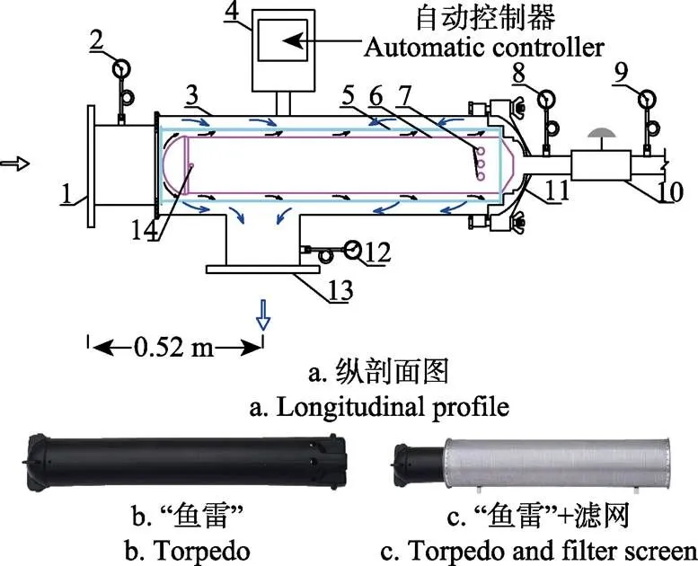
1.进水口 2.进水口压力表 3. 过滤器壳体(筒体) 4. 自动冲洗控制器 5. 滤网 6. 鱼雷 7.污物流入孔 8.自动排污阀进水口压力表 9. 自动排污阀出水口压力表 10. 自动排污阀 11.盖座 12. 出水口压力表 13. 出水口 14. 清水流出孔
1.2 试验材料
物理模型清水试验装置由蓄水池、搅拌池、搅拌电机、进水管、回水管、排污管,前过滤器、测试过滤器、冲洗控制器及检测设备组成,如图2所示。

1.蓄水池 2.搅拌池 3.搅拌电机 4.球阀 5.离心泵 6. 蝶阀7.压力表 8.流量计 9.测试过滤器 10.自动冲洗控制器 11. 回水管 12.排污管 13.进水管 14.排污球阀 15.前过滤器 16.自动排污阀
测试过滤器前端设置有前过滤器,主要目的是保证向测试过滤器提供清洁水。鱼雷网式过滤器由罐体、滤网、鱼雷、自动控制器等主要部分组成,其核心部件为鱼雷,立体图见图1b和1c。该过滤器的关键参数包括罐体长度1.031 m,直径0.254 m;滤网长度0.961 m,直径为0.2 m;进、出口直径均为0.2 m;鱼雷长度1.031 m,直径0.154 m;排污口直径0.05 m。滤网目数为0.178 mm(80目),孔隙率0.33,孔直径0.212 17 mm,丝径为 0.116 2 mm。
1.3 试验方法
试验在清水条件下进行,过滤器的额定设计流量为300 m3/h;从360 m3/h开始以30 m3/h为梯度逐步使进水口流量降到240 m3/h。进水流量调节至稳定后,读取对应流量下的过滤器进出口压力数值,并计算出对应流量的水头损失,根据所得结果得出过滤器流量-水头损失关系曲线。
2 数值计算方法
2.1 控制方程
数值模拟控制方程用雷诺时均方程(Reynolds- Averaged Navier-Stokes,RANS)方程及用RNG湍流模型描述如下:
式中u、u是、方向的流速,m/s;x是坐标,为时间,s;是密度,kg/m3;为流体压力,N/m2;μ为涡黏性系数,m2/s,μ=C·k2/;为单位质量流体的湍流波动能量,m2/s2;为单位质量流体的湍流波动率,m3/s3;G湍流动能平均速度梯度产出项;为雷诺应力,N/m2;其中:
式中为克罗奈克数;μ=μ+μ;为流体黏性系数,m2/s;式(3)~式(6)中各项经验常数取值为C=0.084 5,C2=1.68;σ=σ=1.393,,其中,,0=4.377,= 0.012。滤网用多孔介质阶跃模型来模拟,多孔介质相关参数表达式如下:
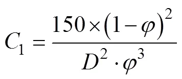
式中为渗透率,m2;1为阻力系数,m-2;2为惯性损失系数,m-1;为滤网孔直径,mm;为孔隙率,%。根据物理试验中采用的滤网参数,即滤网孔直径= 0.212 7 mm,孔隙率0.33,丝径0.116 2 mm,根据给定的参数值,可计算得到=6.63×10⁻¹¹m2,1=1.508× 10¹⁰m-2,2=137 711 m-1。
2.2 网格划分及计算方法
为减少数值模拟的计算工作量和保证计算精度,对过滤器的计算网格进行了优化。将过滤器的网格进行分块划分,网格结构见图3。除了鱼雷头部和末端及出水口段采用四面体非结构网格外,其余部分采用了六面体结构性网格,网格总数为227 354个,网格尺寸3~10 mm。研究的计算区域和控制方程的离散均采用有限体积法。压力-速度耦合采用SIMPLE算法,差分格式采用精度更高的二阶迎风格式。残差标准为1×10⁻³,迭代时间步长为0.000 1s。
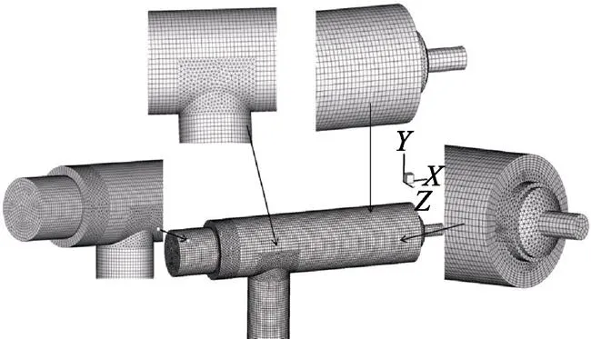
图3 网格划分图
2.3 边界条件
过滤器罐体内壁采用标准壁面函数法进行处理,过滤器进口设为流速进口,该设备的水流方向与轴正向一致,故可设置进口边界条件为=u,=0,=0x为鱼雷网式过滤器的进水口断面平均流速,在300 m3/h时u=2.654 m/s。出口设为压力出口,设定的压力值与试验出口压力一致,即出口压力出=179 000 Pa。
3 结果与分析
3.1 试验与数值模拟结果对比分析
通过试验得到不同流量下进出口压力降关系,并与数值模拟结果进行对比,如表1所示。
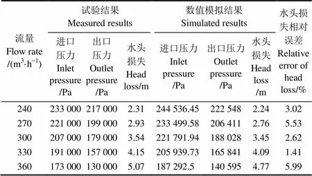
表1 试验与模拟结果对比
表1为物理试验与数值模拟结果的水头损失对比情况,二者相对误差最大为5.99%,小于10%。根据所得结果绘制出过滤器流量-水头损失关系曲线(如图4所示)。试验结果和模拟结果的指数相差不大(0.02),拟合公式中的系数相差0.000 01。计算结果和物理试验结果基本吻合,说明所选模型及参数合理。
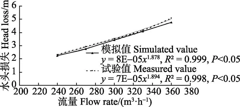
图4 鱼雷网式过滤器模拟水头损失和实测水头损失对比
3.2 数值模拟结果分析
3.2.1 过滤过程数值模拟
图5为过滤器不同平面平均速度矢量图。由图5可以看出,水流从进水管处均匀地流向鱼雷网式过滤器中,当水流流经鱼雷头部时,水流速度分布特性发生了改变,水流从鱼雷头部的下半部分流入下滤网内侧,通过滤网孔进行过滤,而鱼雷头部的上半部分水流则进入上滤网内侧进行过滤。当突然遇到出水口边界时,流速分布发生了巨大的变化,水流由沿轴正向运动快速转变为沿出水管右侧斜向下运动,从而造成出水管左侧的部分区域产生旋涡。流速由进水口的2~3 m/s增大为4~5 m/s,这主要是因为水流进入罐体后过水面积突然缩小而产生流速激增。水流沿着滤网内侧向下游流动过程中流速逐渐减小,并在末端形成低流速区。另外,水流通过滤网后做反向运动,由于水流受到滤网的阻力作用,使得水流通过滤网后流速下降;并在过滤器上部(=0.2~0.4 m)滤网外侧有旋转掺混,最后在出水口汇集。
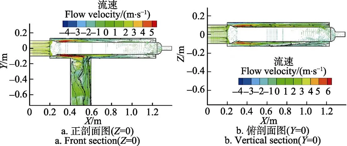
图5 流速矢量分布
图6为过滤器不同平面压力分布图。从图6可知进水管的压力大于出水管的压力。因罐体中滤网和鱼雷的存在,以及出水口边界条件的影响,当水流从进水管流动至出水管处时,会发生局部水头损失和沿程水头损失,故当位置水头和流速水头一定时,进水管的压力大于出水管压力;另外在=0.2~0.4 m处时,滤网上部的内、外压差较大,水流以很大的速度流动并经过滤网孔,从而造成滤网内、外压差较大,但=0.4 m以后上滤网的内、外压差较小,分布较均匀;=0.2~0.6 m处时,滤网下部内、外压差较大,且影响范围很大。这是因为水流从鱼雷头部的下半部分进入滤网,并经过滤网孔,且在=0.4~0.6 m处存在出水口边界,故滤网内、外压差较大,影响范围大,而到=0.6 m处以后,下滤网的内、外压差较小,分布较均匀。

图6 不同断面压力分布
3.2.2 鱼雷部件内部流速分析
鱼雷作为鱼雷网式过滤器核心部件,其内部设计为空心。在其末端设有8个直径为20 mm的圆孔,在其头部设有4个直径为10 mm圆孔。图7为鱼雷内部水流平均流速矢量图。从图7中可以看出,当过滤器开始工作时,水流从鱼雷尾部的小孔进入鱼雷内部,从鱼雷头部的小孔流出。水流在鱼雷内部掺混、流速减小,鱼雷内部的流速值为-1~1 m/s。可以看出水中的泥沙颗粒随着水流进入鱼雷内部,并在鱼雷内部沉淀。这使得滤网内部水流中含沙量减少,也就是说鱼雷起到过滤泥沙的作用,从而延长过滤时间。
图7 鱼雷内部速度矢量分布
Fig.7 Velocity vector distribution of interior torpedo
3.2.3 流速及压力模拟分析
图8表示水流流速沿轴的变化曲线。
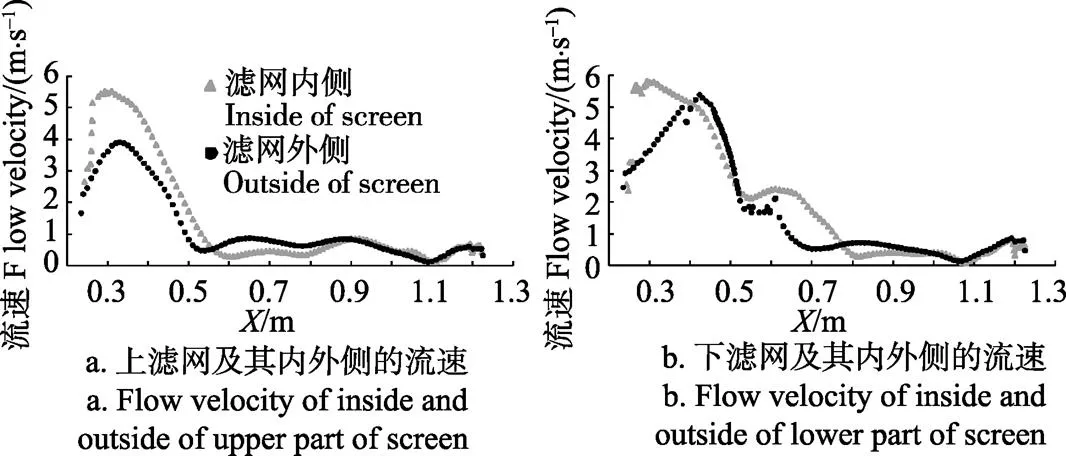
图8 水流流速沿X轴的变化曲线
从图8a中可得出2点:1)滤网上部内侧及外侧的水流流速沿轴的变化分3个阶段:①流速迅速增加阶段。滤网上部内侧及外侧的水流流速都是沿轴迅速增加,但增加幅度不一样,出现流速最大值及其在轴的位置有所差别。如滤网上部内侧的增加幅度大于滤网上部外侧,滤网上部内侧=0.29 m处水流流速最大,流速最大值为5.53 m/s;滤网上部外侧=0.33 m处水流流速最大,流速最大值却为3.9 m/s。由于罐体中鱼雷的存在,过水断面面积突然由大变小,造成滤网上部内、外侧速度迅速上升。②流速迅速减小阶段。滤网上部内侧在=0.3~0.60 m处流速沿轴迅速减小;滤网上部外侧在=0.3~0.55 m也沿轴迅速减小,但减小幅度不如滤网上部内侧。③流速缓慢减小阶段。滤网上部内侧和外侧流速分别在=0.60~1.2 m、=0.55~1.2 m处沿轴缓慢减小,减小幅度相差不大。2)当=0.2~0.6 m时,滤网上部内侧的水流流速比外侧水流流速大,但两者的流速差却沿轴越来越小,两者的最大流速差为4.1 m/s;当=0.6~1.2 m时,滤网上部内、外侧的水流流速相同,流速差几乎为0。从图8b中可得出以下2点:1)滤网下部内、外侧的水流流速沿轴的变化和滤网上部一样也包含3个阶段,但因出水口边界条件(=0.4~0.6 m)的影响,水流流速最大值发生的位置、最大流速值及流速的波动频率同滤网上部有所不同,尤其是滤网外侧,如滤网外侧的流速最大值发生在=0.42 m处,为5.4 m/s;2)=0.41~0.51 m时,滤网下部外侧流速大于内侧,因通过滤网孔的所有水流最终要汇集到出水管的出水口处,从而加大了该处的水流流速值,而其他区域范围滤网下部内侧流速大于外侧;同滤网上部一样,其内、外流速相差很大,最大流速差为2.28 m/s。
综上,过滤器过滤过程中,滤网内、外侧的水流流速沿轴方向分布都不均匀,如鱼雷尾部件附近的滤网,其内、外侧流速相差较小,故水的渗透率较小。由于鱼雷部件的加入,使得滤网内部分成2个高速区域(=0.2~0.6 m)和低速区域(=0.8~1.2 m)。当灌溉水进入过滤器后,在高速区域沿方向的流速很大,使得水中泥沙污物不能停留在滤网表面,而是把水中泥沙推向过滤器尾部,最后沉淀在低速区域。使得整个滤网堵塞不均匀,出水口附近的高速区域(=0.2~0.6 m)不易堵塞,过滤器的堵塞首先从过滤器尾部靠近排污口开始。只要发展到出水口附近才会出现压力差变大,由于过滤器清洗是以进出口压力差为标准进行判断的,因此选择最佳清洗压差需要深入研究。
图9表示压力沿轴的变化曲线。
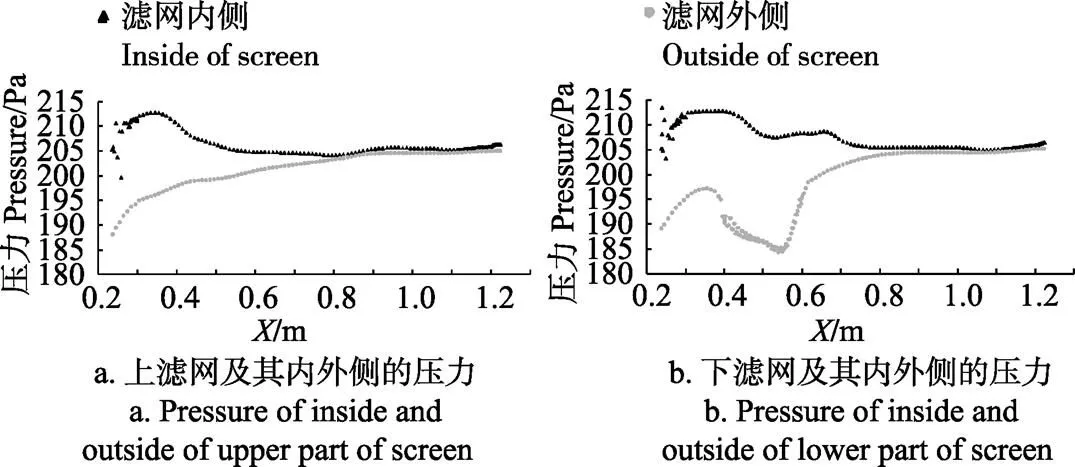
图9 压力沿X轴的变化曲线
从图9a中可得出2点:1)滤网上部内侧及外侧的压力沿轴变化有所不同,尤其是鱼雷头部位置(0.2~0.28 m)。滤网上部外侧的压力沿轴先缓慢增加,当增加至204 kPa(=0.86 m处)趋于稳定;滤网上部内侧压 力沿轴在=0.26~0.33 m时迅速增加,而在=0.33~0.55 m时缓慢减小,减小至205 kPa,压力在=0.55~ 1.2 m处虽有一些波动的,但基本趋于稳定。2)滤网上部内侧压力比外侧的大,但两者的压力差沿轴越来越小,两者的最大压力差为17 kPa左右,最小压差为0.5 kPa。从图9b中可得出以下2点:1)滤网下部内侧和外侧的压力沿轴变化规律及波动程度同滤网上部有所不同,除了受鱼雷头部影响外,出水口边界条件(= 0.40~0.60 m)对滤网下部的压力沿轴分布影响较大。如滤网下部外侧,其压力沿轴的变化可分为4个阶段,即①=0.2~0.35 m时,为压力缓慢增加阶段;②= 0.36~0.55 m时,为压力减小阶段;③=0.55~0.62 m时,为压力迅速增加阶段;④=0.62~1.2 m时,为压力稳定阶段。可见,鱼雷和出水口边界对滤网下部及其内、外侧的压力沿轴的变化影响很大,同时说明压力沿轴的波动幅度较大。2)滤网下部内侧压力比外侧的大,但两者的压力差沿轴越来越小,两者的最大压力差为23 kPa左右,最小压差为0.5 kPa。
综上,滤网内、外侧的压力沿轴方向分布都不均匀,这会导致滤网内、外侧压力差变大,尤其是在滤网下部出水口附近滤网内外侧压差很大,容易造成滤网变形,以及比滤网孔大粒径的污物进入管路系统,从而堵塞灌水器。因此,很有必要选用优质钢丝编制滤网,对过滤器滤网及时冲洗,并且确定最优排污压差。
4 结论与讨论
本文对鱼雷网式过滤器内的流场进行了数值模拟,主要得到以下结论:
1)水流从进水管进入鱼雷网式过滤器并流出出水管的运动状态,指出鱼雷、出水口边界条件对该过滤器的速度流场和压力场分布规律影响很大。尤其是鱼雷部件的影响是尤为突出,其不仅改变了过滤器内部流场分布,而且还起到吸收泥沙的作用。
2)滤网及其内、外侧的水流流速沿轴的变化包含3个阶段:①流速迅速增加阶段;②流速迅速减小阶段;③流速缓慢减小阶段。因鱼雷的存在,以及出水口边界条件的影响,滤网上部及其内、外侧的水流流速和压力沿轴的变化规律与滤网下部及其内、外侧不同。
3)滤网内外压场分布有很大的的差异,滤网内外压差在滤网进口很大,然后缓慢减小。两者的最大压力差为23 kPa左右,最小压差为0.5 kPa;
4)由于鱼雷部件的使用,使得过滤器内进水口附近的水流始终处于高速状态,但在尾部排污口附近形成低速区。得出整个滤网堵塞不均匀,过滤器的堵塞首先从滤网末端开始并向出水口方向发展,对后续滤网的冲洗排污产生重要影响,建议设置最佳排污压差值时需要慎重考虑;另外在出水口附近滤网内外侧压差很大,从而容易造成滤网变形、破坏;故降低鱼雷网式过滤器滤网内、外侧的压力差需要进一步的深入研究。
[1] 杨万龙,宋世良. 叠片式自动反冲洗过滤器的研制[J]. 中国农村水利水电,2005(1):115-117.
[2] 王栋,薛瑞清. 滴灌用水动活塞叠片式自动过滤装置的研制[J]. 节水灌溉,2010(3):15-18.Wang Dong, Xue Ruiqing. Study on terrace automatic filter equipment with piston driven by water for drip irrigation[J]. Water Saving Irrigation, 2010(3): 15-18. (in Chinese with English abstract)
[3] 王燕燕. 自清洗叠片过滤器的设计与研究[D]. 北京:北京化工大学,2010. Wang Yanyan. Design and Research of Self-cleaning Discs-type Filter[D]. Beijing: Beijing University of Chemical Technology, 2010. (in Chinese with English abstract)
[4] 刘焕芳. 自动清洗网式过滤器:中国,ZL200920164576. 6[P]. 2010-09-01.
[5] 王新坤,许颖,涂琴. 微灌系统过滤装置优化选型与配置[J]. 农业工程学报,2011,27(10):160-163. Wang Xinkun, Xu Ying, Tu Qin. Optimal selection and collocation of filter unit in micro-irrigation system[J]. Transactions of the Chinese Society of Agricultural Engineering (Transactions of the CSAE), 2011, 27(10): 160-163. (in Chinese with English abstract)
[6] 杨晓军,刘飞,吴玉秀,等. 新疆农田节水灌溉系统首部过滤设备选型探讨[J].中国农村水利水电,2014(5):76-80. Yang Xiaojun, Liufei, Wu Yuxiu, et al. A discuss on the first part filtration equipment selection in Xinjiang Agricultural water-saving irrigation system[J]. China Rural Water and Hydropower, 2014(5): 76-80. (in Chinese with English abstract)
[7] 刘飞,刘焕芳,宗全利,等. 新型自清洗网式过滤器结构优化研究[J]. 中国农村水利水电,2010,(10):18-21. Liu Fei, Liu Huanfang, Zong Quanli, et al.Research on the new type self-cleaning screen filter’s structural optimization[J]. China Rural Water and Hydropower, 2010, (10): 18-21. (in Chinese with English abstract)
[8] 郑铁刚,刘焕芳,宗全利. 微灌用过滤器过滤性能分析及应用选型研究[J]. 水资源与水工程学报,2008(3):36-45. Zheng Tiegang, Liu Huanfang, Zong Quanli. Analysis and research for the filtering quality and type-selecting of emitter in micro-irrigation[J]. Journal of Water Resources and Water Engineering. 2008(3): 36-45. (in Chinese with English abstract)
[9] 于旭永,刘焕芳,宗全利,等.自吸式全自动网式过滤器运行中存在问题及解决措施[J].节水灌溉,2013(8):51-53.
Yu Xuyong , Liu Huanfang, Zong Quanli, et al. Problems of solutions of the operation of self-cleaning screen filter[J]. Water Saving Irrigation,2013(8): 51-53. (in Chinese with English abstract)
[10] 张力,张凯,张杰武. 新型滴灌系统及附属设备的研发与应用[J]. 中国农村水利水电,2013(4):61-63.
[11] 宗全利,刘飞,刘焕芳,等. 大田滴灌自清洗网式过滤器的水头损失试验[J].农业工程学报,2012,28(16):86-92.
Zong Quanli, Liu Fei, Liu Huanfang, et al. Experiments on water head losses of self-cleaning screen filter for drip irrigation in field [J]. Transactions of the Chinese Society of Agricultural Engineering (Transactions of the CSAE), 2012, 28(16): 86-92. (in Chinese with English abstract)
[12] 张娟娟,徐建新,黄修桥,等.国内微灌用叠片过滤器研究现状综述[J].节水灌溉, 2015(3):59-6.
Zhang Juanjuan, Xu Jianxin, Huang Xiuqiao, et al. Research status and development trend of disc filter in micro-irrigation[J].Water Saving Irrigation, 2015(3):59-65. (in Chinese with English abstract)
[13] 宗全利,刘焕芳,郑铁刚,等.微灌用网式新型自清洗过滤器的设计与试验研究[J]. 灌溉排水学报,2010,29(1): 78-82.
Zong Quanli, Liu Huanfang, Zheng Tiegang, et al. The design and experimental study on new net self cleaning filter for micro-Irrigation[J].Journal of Irrigation and Drainage, 2010, 29(1): 78-82. (in Chinese with English abstract)
[14] 刘焕芳,刘飞,谷趁趁,等. 自清洗网式过滤器水力性能试验[J]. 排灌机械工程学报,2012,30(2):203-208. Liu Huanfang, Liu Fei, Gu Chenchen, et al. Experiment on hydraulic performance of self-cleaning screen filter [J]. Journal of Drainage and Irrigation Machinery Engineering, 2012, 30(2): 203-208. (in Chinese with English abstract)
[15] Yurdem H, Demir V, Degirmencioglu A. Development of a mathematical model to predict head losses from disc filters in drip irrigation systems using dimensional analysis[J]. Biosystems Engineering, 2008, 100(1): 14-23.
[16] Mailaphlli D R, Marques P A A, Thomas K J. Performance evaluation of hydrocyclone fiter of micro irrigation [J]. Engineering Agricultural, Jaboticabal, 2007, 27(2): 373-382.
[17] Duran-Ros M, Arbat G, Barragan J, et al. Assessment of head loss equations developed with dimensional analysis for microirrigation filters using effluents[J]. Biosystems Engineering, 2010(106): 521-526.
[18] Capra A, Scicolone B. Assessing dripper clogging and filtering performance using municipal wastewater[J]. Irrigation and Drainage, 2005(54): S71-S79.
[19] Duran-Ros M, Puig-Brgues J, Arbat G, et al. Performance and backwashing efficiency of disc and screen filters in micro irrigation systems[J]. Biosystem Engineering, 2009(103): 35-42.
[20] 王新坤,高世凯,夏立平,等. 微灌用网式过滤器数值模拟及结构优化[J]. 灌排机械工程学报,2013,31(8): 719-723. Wang Xinkun, Gao Shikai, Xia Liping, et al. Numerical simulation and structural optimizationof screen filter in micro-irrigation[J]. Journal of drainage and irrigation machinery engineering, 2013, 31(8): 719-723. (in Chinese with English abstract)
[21] 王栋蕾,宗全利,刘建军. 微灌用自清洗网式过滤器自清洗结构流场分析与优化研究[J]. 节水灌溉,2011(12):5-8. Wang Donglei, Zong Quanli, Liu Jianjun. Flow analysis and structure optimization of self-cleaning nets filter for micro-irrigation[J]. Water Saving Irrigation, 2011(12): 5-8. (in Chinese with English abstract)
[22] 宗全利,郑铁刚,刘焕芳,等. 滴灌自清洗网式过滤器全流场数值模拟与分析[J]. 农业工程学报,2013, 29(16): 57-63. Zong Quanli, Zheng Tiegang, Liu Huanfang, et al. Numerical simulation and analysis on whole flow field for drip self-cleaning screen filter[J]. Transactions of the Chinese Society of Agricultural Engineering (Transactions of the CSAE), 2013, 29(16): 57-65. (in Chinese with English abstract)
[23] 王志斌,陈文梅,褚良银,等. 旋流分离器中固体颗粒随机轨道的数值模拟及分离特性分析[J]. 机械工程学报,2006,42(6):34-39. Wang Zhibin, Chen Wenmei, Chu Liangyin, et al. Numerical simulation of particale motion trajectory in a hydrocyclone using a stochastic trajectory model[J]. Chinese Journal of Mechanical Engineering, 2006, 42(6): 34-39. (in Chinese with English abstract)
[24] Dai GQ, Li JM, Chen WD. Numerical prediction of the liquid flow within a hydrocyclone[J]. Chemical Engineering Journal, 1999, 74: 217-227.
[25] 刘新阳. 微灌用水力旋流器内水沙两相湍流数值模拟[D]. 武汉大学,2009. Liu Xinyang. Numerical Simulation of Water and Sediment Two-phase Flow in Hydrocyclone for Micro-irrigation[D]. Wuhan: Wuhan University, 2009. (in Chinese with English abstract)
[26] 阿力甫江·阿不里米提,虎胆·吐马尔白,马合木江·艾合买提,等. 直冲洗鱼雷网式过滤器内流场的数值模拟[J]. 节水灌溉,2014(10):6-10. Alipujiang A, Hudan T, Mahemujiang A, et al. Numerical simulation of flow field in torpedo filer[J]. Water Saving Irrigation, 2014(10): 6-10. (in Chinese with English abstract)
[27] 阿力甫江·阿不里米提,陶鸿飞,马英杰,等. 不同出水口位置下全自动鱼雷网式过滤器内部流场的数值模拟[J]. 灌溉排水学报,2015,34(12):47-51. Alipujiang A, Tao hongfei, Ma yingjie, et al. Numerical simulation of internal flow field in automatic screen filter with torpedo under different outlet positions[J]. Journal of Irrigation and Drainage, 2015, 34(12): 47-51. (in Chinese with English abstract)
[28] 阿力甫江. 阿不里米提. 8寸鱼雷除砂网式全自动冲洗过滤器:中国,CN201310567875.5[P]. 2015-05-27.
[29] 阿力甫江. 阿不里米提. 6寸鱼雷除砂网式全自动冲洗过滤器:中国,CN201310567509.X[P]. 2015-05-27.
[30] 阿力甫江. 阿不里米提. 5寸鱼雷除砂网式全自动冲洗过滤器:中国,CN201410755532.6[P]. 2015-04-22.
Numerical simulation on flow field of screen filter with torpedo in micro-irrigation
Alifujiang·Abulimiti1,2,3, Hudan·Tumaerbai1※, Mulati·Yusaiyin1,3, Mukeran·Awa3
(1830052; 2.8300133.830019)
In order to deeply understand the flow distribution of the torpedo screen filter, the Reynolds-averaged Navier-Stokes (RANS) equation and Re-Normalization Group (RNG)turbulence closure model were used to simulate the flow field of this filter system. To ensure the reliability of the numerical simulation, the physical experiment results were compared to the numerical simulation results, and the result showed that the maximum relative error between the head loss in the physical experiment and the numerical simulation was 5.99% when the filtering system was operated at a maximum flow rate of 360 m3/h, indicating reliability of the simulation method. The simulation results showed that the torpedo components and the boundary conditions of the outlet notably affected the distribution rules of both the velocity and the pressure fields for the filter, especially for the torpedo components. The distributions of the flow velocities of inside and outside of the screen along the-axis were not uniform during the filtering process. And the flow velocity distributions inside and outside of the filter screen along the-axis were divided into 3 stages: 1) a rapid increase; 2) a rapid decrease; and 3) a gradual decrease. The maximum velocities inside and outside of the screen and their spatial locations along the-axis were different. For the upper part of the screen, the inside flow velocity increased in a larger amplitude than did the outside flow velocity, and the flow velocity achieved its maximum (5.53 m/s) at thevalue of 0.29 m. The outside water flow velocity of the upper part of the screen achieved its maximum value (3.9 m/s) at thevalue of 0.33 m. When thevalue ranged from 0.2 to 0.6 m, the inside flow velocity of the upper part of the screen was larger than that of the outside; however, the difference in the flow velocity along the-axis continually decreased from the maximum difference of 4.1 m/s. For the lower part of the screen, the maximum flow velocity and its position of lower part of the screen was 5.4 m/s and 0.42 m, respectively. When thevalue was 0.41-0.51 m, the flow velocity of the water in the outside area of the lower part of the screen was larger than that of water in the inside area. Nonetheless, the flow velocities of water in the other inside of lower screen were higher than those of water in the outside, and the maximum difference in the flow velocity was 2.28 m/s. There was a notable difference in the pressure distributions along the inside and outside of the screen. The pressure of the inside along the-axis first rapidly increased, then gradually decreased, and finally stabilized. In contrast, the pressure of the outside along the-axis exhibited a greater variation; for example, the pressure rapidly decreases at the outlet, and the fluctuations along theaxis are relatively large. The pressure of the inside of the screen was larger than that of the outside; however, the pressure differences along the-axis continually decreased, and the maximum and minimum pressure differences between the two were approximately 23 and 0.5 kPa, respectively. This indicated that the screen clogging was not evenly distributed, and the screen clogging began at the downstream end of the screen and developed progressively upstream towards the outlet. This phenomenon significantly affected the cleaning process of the filter. Therefore, it is strongly suggested that in a practical application the optimum drainage differential pressure must be circumspectly considered.
flow fields; flow velocity; pressure; torpedo screen filter; numerical simulation; turbulence model
10.11975/j.issn.1002-6819.2017.03.014
S277.9+5
A
1002-6819(2017)-03-0107-06
2016-07-14
2016-10-10
国家自然科学基金资助项目“大规模滴灌条件下棉田土壤盐分积累过程与排盐模式研究”(51469033)(2015-2018)
阿力甫江·阿不里米提,男(维吾尔族),博士生,主要从事高效节水与水盐运移理论研究。乌鲁木齐 新疆农业大学水利与土木工程学院,830052。Email:2414655347@qq.com。
虎胆·吐马尔白,男,教授,博士生导师,主要从事高效节水与水盐运移理论研究。乌鲁木齐 新疆农业大学水利与土木工程学院。830052。Email:hudant@hotmail.com。
阿力甫江·阿不里米提,虎胆·吐马尔白,木拉提·玉赛音,木克然·阿娃. 微灌鱼雷网式过滤器全流场数值模拟[J]. 农业工程学报,2017,33(3):107-112. doi:10.11975/j.issn.1002-6819.2017.03.014 http://www.tcsae.org
Alifujiang·Abulimiti, Hudan·Tumaerbai, Mulati·Yusaiyin, Mukeran·Awa.Numerical simulation on flow field of screen filter with torpedo in micro-irrigation [J]. Transactions of the Chinese Society of Agricultural Engineering (Transactions of the CSAE), 2017, 33(3): 107-112. (in Chinese with English abstract) doi:10.11975/j.issn.1002-6819.2017.03.014 http://www.tcsae.org
