六足步行机器人腿部机构运动学分析
2016-12-19张金柱金振林陈广广
张金柱,金振林,2※,陈广广
(1. 燕山大学机械工程学院,秦皇岛 066004; 2. 上海交通大学机械系统与振动国家重点实验室,上海 200240)
六足步行机器人腿部机构运动学分析
张金柱1,金振林1,2※,陈广广1
(1. 燕山大学机械工程学院,秦皇岛 066004; 2. 上海交通大学机械系统与振动国家重点实验室,上海 200240)
为了提高农业自动化程度,拓宽农业机器人的应用范围,提高农业机器人对工作环境的适应性及工作的灵活性,该文介绍了一种六足步行机器人三自由度腿部机构。该机构由并联驱动机构和行走机构组成,既具有并联机构的特点,又具有很好的防护性。该文建立了驱动机构动平台线速度与角速度之间的关系矩阵和该腿部机构全雅可比矩阵,绘制了全雅可比矩阵条件数分布图,建立了并联驱动机构和腿部行走机构显式3×3×3形式Hessian矩阵。在满足步矩为300 mm、越障高度为200 mm的条件下,利用组合多项式的方法,对该腿部足端进行轨迹规划,并求出了足端轨迹函数。将该轨迹函数作为足端输入,分别绘制了机构驱动关节在摆动相的角速度、角加速度理论曲线和虚拟样机仿真曲线。分析曲线中的数据可得角速度、角加速度的理论与仿真结果相近度均可达到10-3mm,从而验证了理论分析的正确性。该研究为六足机器人的开发和控制提供了参考。
机器人;计算机仿真;运动学;雅可比矩阵;轨迹规划
0 引言
近年来在农业自动化领域,农业机器人的研究得到了众多学者的重视[1-5],但专门用于农业领域的机器人并不多见[6]。据中国农业主管部门调查发现,随着中国现代农业生产方式从粗放型向集约型的不断转变[7],农业从业人员迫切希望在更多的农业作业领域应用机器人。因此,农业机器人的多样化是农业机器人发展的趋势。
六足步行机器人作为农业机器人的一种,拥有稳定性好、运动灵活性好、占地面积小、对地面适应性好等特点[8],可作为对履带式和导轨式农业移动平台的补充,大大的扩展了机器人在农业领域的作业场合。并联结构腿作为六足机器人腿的一种,具有承载能力强、结构紧凑、驱动或电机靠近基座或者在基座上等特点,可使其作为步行机器人腿部机构。在并联腿的研究领域,相关学者[9-13]做了大量研究工作,并取得了丰硕的成果,上海交通大学高峰团队研制的“章鱼机器人”也采用并联结构腿。然而,上述机器人的腿部驱动或电机随腿部一起运动,很难进行腿部防护,使该类机器人易受雨天、雷电、风沙及意外撞击的影响,制约了其在农业领域的广泛应用。本文介绍的六足机器人采用的腿部机构为三自由度2RUS+RU+FD机构(其中R、U、S分别表示转动副、虎克铰、球副;FD表示平行四边形放大机构),并将该机构3个R副作为驱动副,以期提高六足机器人的防护特性,拓宽其应用领域。
低损伤、精细操作[14]是现代农业对农业机器人的要求。雅可比矩阵和Hessian矩阵是农业机器人实现上述工作指标的理论基础。目前,针对少自由度并联机构的雅可比矩阵和Hessian矩阵,国内外学者做了大量的研究工作[15-19],然而专门针对并联驱动的串并混联机构的全雅可比矩阵和Hessian矩阵的研究鲜有报道。本文在考虑动物的行走过程本质[20]的前提下,建立了2RUS+RU驱动机构动平台的线速度与角速度之间的关系矩阵、2RUS+RU驱动机构的统一量纲雅可比矩阵和腿部机构的全雅可比矩阵以及并联驱动机构和行走机构二者各自的3×3×3的Hessian矩阵,以期为六足步行机器人的腿部设计与精确控制提供参考。
1 腿部机构描述
本文所研究的腿部机构为一种六足步行机器人腿部机构,该机器人采用六条相同的机械腿,图1所示为该六足步行机器人整体结构示意图,图中所示行走方向为主运动方向,在该方向上机器人的基本运动要求为:步距300 mm,越障高度200 mm。此外,为了提高机器人腿部的灵活性,利用半球形足使其与地面以点接触的形式接触。
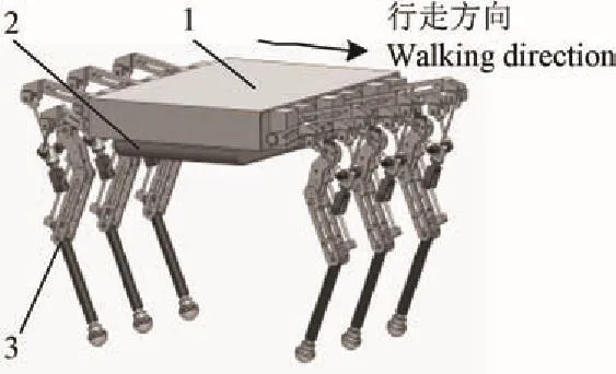
图1 六足步行机器人整体结构图Fig.1 Overall structure of six-legged warking robot
图2所示为该机器人腿部机构简图,由图2可知该腿部机构由驱动机构和行走机构串联而成,其中,驱动机构为2RUS+RU并联机构,行走机构为平行四边形机构(即FD机构),二者通过一个中间球副S连接。在2RUS+RU中,2条RUS支链相对于RU支链所在的平面对称布置,在初始状态下,RU支链和FD机构布置于同一竖直平面内。设机构的主要几何参数为RDiUi=mi(i=1,2,3),UiSi=li(i=1,2),UiG=l3,SiG=a,R4R1=l4,R1R3=l5,R1R2=l6,R1B=c,SB=lg,R5C=l7,GS=l33,RD1RD2=d,O0RD3=h1。定义:∥表示平行,⊥表示垂直。则机构中杆件和运动副的几何关系有l4∥l5,l5∥l7,l6∥R3R5,l4⊥S1S2,lg⊥l6。
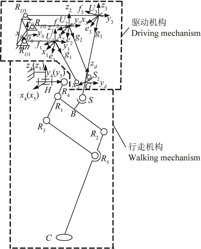
图2 六足步行机器人腿部机构简图Fig.2 Sketch map of leg mechanism of six-legged walking robot
坐标系建立方面,如图2所示,以RD1和RD2连线的中点O0为原点建立固定坐标系O0-x0y0z0,其中x0,y0,z0为坐标轴,x0∥RD1RD2,y0⊥RD1RD2,z0由右手螺旋定则确定;以G为坐标原点建立动坐标系G-xdydzd,xd,yd,zd为坐标轴,xd∥S1S2,yd⊥S1S2,zd∥l3;为方便各支链连杆姿态描述,以Ui为坐标原点建立各支链参考坐标系U-xiyizi(i=1,2,3),其中xi,yi,zi为坐标轴,yi∥mi,zi⊥mi且zi在竖直平面内方向向上,xi由右手螺旋定则确定;同时,以Ui为坐标原点建立各支链连杆连体坐标系Ui-eifigi(i=1,2,3),其中ei,fi,gi为坐标轴,fi与相应支链虎克铰远离杠杆的转动轴线重合,gi∥li,ei由右手螺旋定则确定;以H为原点建立参考坐标系H-x4y4z4和动参考坐标系H-x5y5z5,有x4∥x0,x5⊥l4且x5⊥l6,y4∥y5∥y0,z4和z5由右手螺旋定则确定。
2 机构的速度分析
2.1 2RUS+RU驱动机构速度分析
2.1.1 2RUS+RU驱动机构速度伴随性分析
利用旋转变换矩阵T来表示动坐标系G-xdydzd相对于固定坐标系O0-x0y0z0的位姿变化。由图2可知,动坐标系经过如下变化

式中TG为动坐标系相对定坐标系的齐次变换矩阵;xdt, ydt, zdt为在变化过程中动坐标系的x, y和z轴。θp3表示转动副RD3相对初始位置的转角,α1, β1分别为虎克铰U3的2个转轴相对于竖直位置的转角,rad;h1为O0RD3的竖直距离,mm;l3为连杆U3G的长度,mm。且有如下关系

由机构自由度组成可以看出,α,β为并联驱动机构动平台XY欧拉角(即动坐标系先处于如图2中初始位置,然后绕动坐标系的x轴旋转α角,再绕动坐标系的y轴旋转β),rad。对于G点位置矢量,由坐标变换得

式中G=[x0y0z0]T为动平台参考点G在固定坐标系中的位置矢量。
由式(1)~式(3)位置关系得

式中m3为杠杆RD3U3的长度,mm;x0,y0,z0分别为G点的三维横纵坐标,mm;θp3表示转动副RD3相对初始位置的转角,rad;为书写方便,文中规定sβ=sinβ,cβ=cosβ,sα=sinα,cα=cosα,cθp3=cosθp3,sθp3=sinθp3。由式(4)可以看出,姿态和位置并不独立,它们之间存在一定的伴随关系。

对式(4)求导,整理得式中v为动平台末端线速度,mm/s;γ并联机构绕z轴的欧拉角,rad。
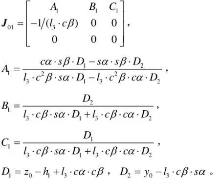
由于机构的角速度与欧拉角角速度之间的关系[21]为
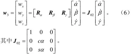
式中J01为动平台线速度与欧拉角角速度之间的关系矩阵;w3为动平台末端角速度矢量,wx、wy、wz分别为w3的3个坐标分量,rad/s;Rα、Rβ、Rγ分别为欧拉角α、β、γ的转轴。
由此得动平台末端线速度v和角速度w3之间的关系为

式中J02⋅ J01为2RUS+RU驱动机构动平台线速度与角速度之间的关系矩阵。
2.1.2 2RUS+RU驱动机构雅可比矩阵的建立
根据几何关系,建立矢量方程为

式中G为G点在固定坐标系中的位置矢量;ui,RDi和gi(i=1,2,3)分别表示支链i的虎克铰中心点Ui、转动副中心点RDi(i=1,2,3)在固定坐标系O0-x0y0z0中的位置矢量和连杆方向矢量;Li(i=1,2,3)为i支链连杆在固定坐标系O0-x0y0z0中的长度矢量;li为i支链连杆杆长,mm;ni=[0 cθpisθpi]T(i=1,2,3)为驱动杠杆的单位方向矢量;θpi为转动副RDi(i=1,2,3)相对于初始位置的转角,rad;mi(i=1,2,3)为杠杆i的杆长,mm;ai(i=1,2)分别为杆SiG的长度矢量。
对式(8)、式(9)两式分别对时间求导,整理得

联合式(7)~式(11)得并联驱动机构雅克比矩阵为

式中J0为并联驱动机构的速度雅克比矩阵;nit=[0 cθp3sθp3]T为ni求导所得。
又由于点S和点G之间的速度关系为

式中l33为杆GS在固定坐标系中的长度矢量,l33为杆GS的长度,mm;vsp为点S在固定坐标系中的速度矢量;I 为3×3单位矩阵;3ˆg表示g3的反对称矩阵。
由式(13)得

式中J1为点S和点G之间速度映射矩阵。
2.2 行走机构雅可比矩阵求解
根据图2中点C和S在各个坐标系中的几何关系得
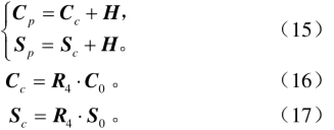
式中Cp,Sp,Cc,Sc,S0,C0分别表示C和S点在固定坐标系、参考坐标系、动参考坐标系中的位置矢量;B0为B点在动参考坐标系中的位置矢量;R4=Rot(y4, θ3), H=[0 lylz]T;y4为参考坐标系H-x4y4z4的坐标轴;θ3为行走机构相对初始位置绕y4轴转过的角度,rad;ly、lz分别为H点在固定坐标系中沿y轴和z轴方向坐标,mm。
在动参考坐标系中,得点C和θ1,θ2之间的位置关系

式中θ1,θ2分别为杆件R4R1和R1R2相对于动参考坐标系H-x5y5z5中的y5轴转过的角度,rad;l4、l5、l6、l7分别为杆件R4R1、R1R3、R1R2、R5C的长度,mm;xc0、yc0、zc0分别为点C在动参考坐标系中的坐标,mm。
在动参考坐标系中,得θ1,θ2和点B之间的位置关系

式中c为杆件R1B 的杆长,mm;xb0、yb0、zb0分别为点B在动参考坐标系中的坐标,mm。
在动参考坐标系中,得点S和点B之间的位置关系

式中xs0、ys0、zs0分别为点S在动参考坐标系中的坐标,mm;lg为杆件SB的杆长,mm。
式(15)两端分别对时间求导得

式中vcp, vsp, vcc, vsc分别为点C和点S在固定坐标系和参考坐标系中的速度矢量。
为了方便vcc提取,由式(16)得

式中xcc、zcc为速度矢量vcc的x轴和y轴方向分量,mm。
式(16)~式(20)两端分别对时间求导,构造得

式中vyc0、vzc0、vys0、vzs0分别表示点C和点S在动参考坐标系中速度矢量沿着y轴和z轴方向的分量,mm/s;1θ˙、2θ˙、3θ˙分别为角θ1、θ2和θ3对时间的导数,rad/s。

则由式(21)~式(23)得行走机构的速度关系为

2.3 腿部机构全雅可比矩阵及其条件数
腿部机构全雅可比矩阵为输入转动副RDi的转动角速度与足端点C在固定坐标系中的速度vcp之间的映射关系。由式(12)~式(14)和式(24)得腿部机构全雅可比矩阵为

式中J为腿部机构全雅克比矩阵。
依据文献[22]中雅克比条件数的定义,可知雅克比矩阵条件数随足端点C的位置变化而变化。为了说明雅可比矩阵在评价运动学性能方面的有效性[23],给定一组机构的几何参数如下(单位为mm):d=276,h1=70,a=100,l1= l2=200,l3=250,l33=120,m1=m2=200,m3=370,c=370,l4=l5=200,l6=300,l7=450,ly=190,lz=55,lg=46.5。基于上述全雅可比矩阵J,参照腿部越障和步矩要求,给定转动副的转动角度在[-45°,45°]范围内转动时,全雅可比矩阵J的条件数k(J)在足端点C的z坐标(相对于固定坐标系)为−700 mm时随足端点C的x坐标和y坐标变化的分布规律如图3所示,此外,足端点C的z坐标为−600 、−800 mm时腿部全雅可比矩阵J的条件数k(J)随x坐标和y坐标变化的分布规律与图3类似。由此可知,腿部速度全雅可比矩阵条件数k(J)在工作空间内连续分布,在工作空间的中心区域条件数k(J)的值较小,且变化平缓,说明在此区域机构的灵活性较好,满足机器人步距300 mm,越障高度200 mm的主体运动要求。

图3 足端点的z坐标为−700 mm时的全雅可比矩阵条件数分布图Fig.3 Distribution diagram of conditional number of entire jacobian matrix (z coordinate of foot endpoint is −700 mm)
3 腿部机构加速度分析
3.1 并联驱动机构加速度分析
对式(10)和式(11)两端分别对时间求导得
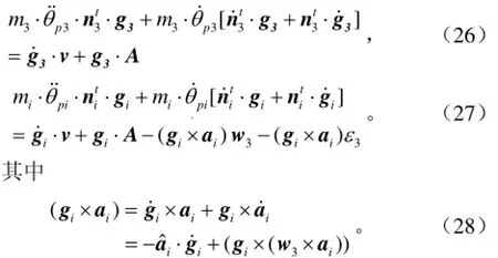
由式(8)、式(9)中矢量关系有

由式(29)两端对时间求导得

则由式(26)~式(30)得

将式(31)变形,写为

其中

为并联驱动机构的3×3×3形式的Hessian矩阵,式中的各项因子可由式(31)求得。
3.2 腿部行走机构加速度分析
对于行走机构,对式(23)的两端对时间求导得

将式(33)变形,写为

利用HXij表示上式中HXi(i=1~4)的第j(j=1~3)个元素,该元素为三维列矢的3×3矩阵,式中各项因子可由式(33)求得。结合设计过程可知,以上速度和加速度模型为控制模型的建立和控制系统的搭建提供了参考。
4 腿部机构运动学仿真验证
4.1 单腿足端轨迹规划
多足机器人的步态规划对机器人运动的灵活性和平稳性有很大影响[24-25],文中以六足机器人为例。根据对六足昆虫行走方式的研究[26-27],发现六足昆虫的行走方式大都为三角步态,在此步态下,腿部的主要运动(前进后退、下蹲起立)及腿部载重和快速奔跑时主要承载力都分布在腿部的矢状面,腿部冠状面的运动主要为平衡、转弯、受冲击时的左右移动[28]。因此,本文以机器人直线行走(矢状面内的运动)为例,针对有障碍物的地面,为减少机器人运动过程中机身震动,提高运动稳定性,使其重心始终保持水平运动,以轨迹平顺、落地平稳及满足越障要求为目标,对腿部足端进行轨迹规划;考虑设计要求为越障高度H=200 mm,步距S=300 mm的条件下,为了更加方便的描述轨迹曲线,建立轨迹坐标系A-xyz如图所示,其中坐标原点与A点重合,y轴方向由A指向D,z轴竖直向上,x轴由右手螺旋定则确定。图4为直线行走时的腿部位姿及足端轨迹示意图。
为了让机器人在行走的过程碰撞少,平顺性好,把轨迹摆动相分为3段,分别为线段AEB,BC,CFD。其中AEB可以避免在起步的过程中与足端近前方的突起相碰撞,BC段为匀速直线运动,提高了电机输入的稳定性,CFD段可以增加落地的平稳性。

图4 腿部行走位姿及足端轨迹示意图Fig.4 Schematic diagram of walking pose of leg and trajectory of foot
综合考虑该腿部机构运动性能和机器人的行走速度要求,设定该机器人单腿行走周期T=4 s,其中摆动相时间为TswinD=2 s,支撑相时间为Tstance=2 s。为了确保机器人在运动过程中平稳无冲击,且具有较好的起落特性,设定足端点在摆动相轨迹上各点的状态量如表1所示。
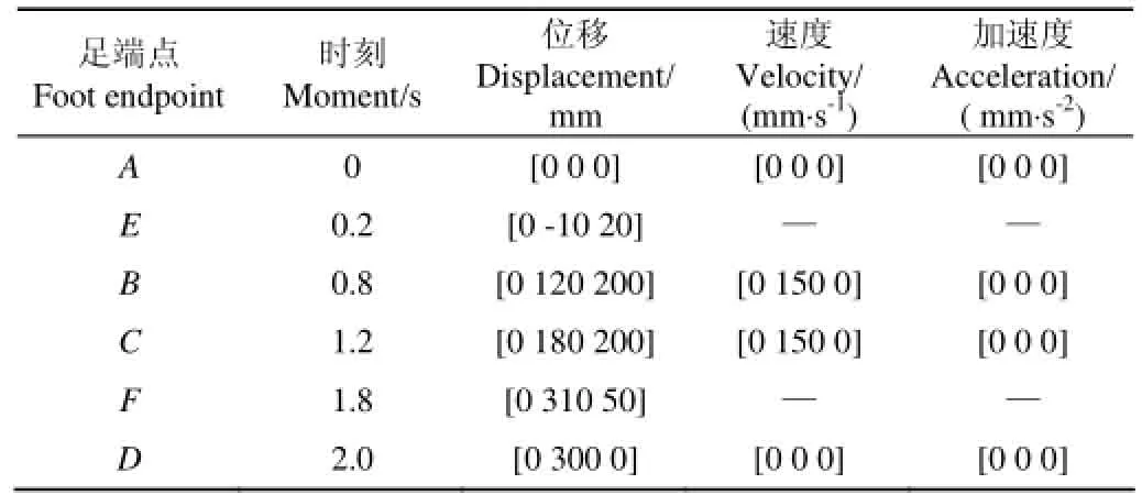
表1 足端点在摆动相轨迹上各点的状态量Table 1 State quantity of foot endpoint in trajectories of swing phase
设线段AEB、CFD的多项式表达式均为

式中g(t)=[x(t) y(t) z(t)]T,ai=[aixaiyaiz]T。
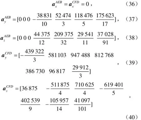
由上述设定状态量得AEB和CFD段的曲线都为6次多项式曲线,为了表达简洁,规定多项式系数向量组成为

式中a为轨迹多项系数组成的向量。
将足端点在摆动相轨迹上各点的状态量带入表达式(34)中得各段多项式的系数向量为
BC段为匀速运动,则得轨迹表达式为

式中x(t),y(t),z(t)分别为足端点的3个坐标分量。
4.2 基于上述轨迹的逆运动学仿真
利用表1中提供的几何参数,将上述摆动相的轨迹函数作为理论速度模型和仿真模型的足端输入,得到腿部的驱动转动副的角速度、角加速度随时间的变化曲线如图5所示。
经过对图5的分析表明,当该腿部机构的足端按给定的运动规律运动时,利用上述建立的速度、加速度模型计算出的驱动关节的角速度、角加速度与利用ADAMS教学版软件中的函数控制法(即将上述所得轨迹函数作为足端的控制输入函数)进行运动仿真的结果吻合且精确度可达到10-3,从而说明了上述腿部速度、加速度模型的正确性。同时从仿真结果可知,驱动关节的角速度最大值小于60 °/s(约0.33π rad/s)、角加速度的最大值小于220 °/s2(约1.22π rad/s2),表明该腿部机构在按照所规划轨迹运动过程中所需驱动转速和转矩较小,对驱动是有利的,由此表明了轨迹规划的合理性。上述研究结果为控制和驱动电机的选取提供了参考。

图5 角速度及角加速度理论、仿真结果Fig.5 Theory and simulation results of Angular velocity and angular acceleration
5 结论
1)建立了2RUS+RU机构的速度关系矩阵、腿部机构3×3形式的全雅可比矩阵以及腿部各组成机构显式3×3×3形式Hessian矩阵,绘制了雅克比矩阵条件数分布规律。该分布规律表明:2RUS+ RU+FD在工作空间内的运动灵活性较好,满足腿部越障高度为200 mm、步距为300 mm的主体运动要求。
2)理论计算结果和仿真结果具有很好的一致性且精确度可达到10-3mm,从而验证了理论模型的正确性。同时,从仿真结果中的驱动关节角速度和角加速度变化曲线可以看出,驱动关节的角速度最大值小于0.33π rad/s、角加速度的最大值小于1.22π rad/s2,所需驱动转速和转矩较小表明了轨迹规划的合理性。
本文研究的成果为该腿部机构的进一步研究提供了参考,为拓展农业机器人的应用范围及扩大六足机器人的应用领域提供了参考。
[1] Shigehiko H, Kenta S. Evaluation of a strawberry-harvesting robot in a field test[J]. Bio Systems Engineering, 2010, 105(2): 160-171.
[2] Kanae T, Tateshi F, Akira A, et al. Cherry-harvesting robot[J]. Compute Electron Agriculture, 2011, 63(1): 65-72.
[3] 纪超,冯青春,袁挺,等. 温室黄瓜采摘机器人系统研制及性能分析田[J]. 机器人,2011,33(6):726-730. Ji Chao, Feng Qingchun, Yuan Ting, et al. Development and performance analysis on cucumber harvesting robot system in greenhouse[J]. Robot, 2011, 33(6): 726-730. (in Chinese with English abstract)
[4] 牛雪梅,高国琴,刘辛军,等. 三自由度驱动冗余并联机构动力学建模与试验[J]. 农业工程学报,2013,29(16):31-41. Niu Xuemei, Gao Guoqin, Liu Xinjun, et al. Dynamics modeling and experiments of 3-DOF parallel mechanism with actuation redundancy[J]. Transactions of the Chinese Society of Agricultural Engineering (Transactions of the CSAE), 2013, 29(16): 31-41. (in Chinese with English abstract)
[5] Tang Jinglei, Jing Xu, He Dongjian, et al. Visual navigation control for agricultural robot using serial BP neural network[J]. Transactions of the Chinese Society of Agricultural Engineering (Transactions of the CSAE), 2011, 27(2): 194-198.唐晶磊,景旭,何东健,等. 基于串行BP网络的农业机器人视觉导航控制[J]. 农业工程学报, 2011, 27(2): 194-198. (in English with Chinese abstract)
[6] 崔冰艳,金振林. 农业机器人新型肘关节的静力学性能分析[J]. 农业工程学报,2011,27(3):122-125. Cui Bingyan, Jin Zhenlin. Analysis of statics performance for a novel elbow joint of agricultural robot[J]. Transactions of the Chinese Society of Agricultural Engineering (Transactions of the CSAE), 2011, 27(3): 122-125. (in Chinese with English abstract)
[7] 杨邦杰,裴志远,周清波,等. 我国农情遥感监测关键技术研究进展[J]. 农业工程学报,2002,18(3):191-194. Yang Bangjie, Pei Zhiyuan, Zhou Qingbo, et al. Key technologies of crop monitoring using remote sensing at a national scale: Progress and problems[J]. Transactions of the Chinese Society of Agricultural Engineering (Transactions of the CSAE), 2002, 18(3): 191-194. (in Chinese with English abstract)
[8] 荣誉,金振林,曲梦可. 三自由度并联机械腿静力学分析与优化[J]. 农业工程学报,2012,28(20):41-49. Rong Yu, Jin Zhenlin, Qu Mengke. Statics analysis and optimal design of 3-DOF parallel mechanical leg[J]. Transactions of the Chinese Society of Agricultural Engineering (Transactions of the CSAE), 2012, 28(20): 41-49. (in Chinese with English abstract)
[9] Sugahara Y, Carbone G, Hashimoto K, et al. Experimental stiffness measurement of WL-16RⅡbiped walking vehicle during walking operation[J]. Journal of Robotics and Mechatronics, 2007, 19(3): 272-280.
[10] 王洪波,徐桂玲,胡星,等. 四足并联腿步行机器人动力学[J]. 机械工程学报,2012,48(23):76-82. Wang Hongbo, Xu Guiling, Hu Xing, et al. Dynamics of quadruped walking robot with parallel leg mechanism[J]. Journal of Mechanical Engineering, 2012, 48(23): 76-82. (in Chinese with English abstract)
[11] 崔冰艳. 仿生机器人并联关节/运动单元的性能分析与设计[D]. 秦皇岛:燕山大学,2011:83-125. Cui Bingyan. Performance Analysis and Design for Parallel Joint/kinematical Unit of Bionic Robot[D]. Qinhuangdao: Yanshan University, 2011: 83-125. (in Chinese with English abstract)
[12] 程刚. 并联式仿生机械腿结构设计及动力学研究[D]. 北京:中国矿业大学,2008. Chen Gang. Study on Structure Design and Dynamic Performance of the Parallel Bionic Robot Leg[D]. Beijing: China University of Mining and Technology, 2008. (in Chinese with English abstract)
[13] 荣誉,金振林,崔冰艳. 六足农业机器人并联腿构型分析与结构参数设计[J]. 农业工程学报,2012,28(15):9-14. Rong Yu, Jin Zhenlin, Cui Bingyan. Configuration analysis and structure parameter design of six-leg agricultural robot with parallel-leg mechanisms[J]. Transactions of the Chinese Society of Agricultural Engineering (Transactions of the CSAE), 2012, 28(15): 9-14. (in Chinese with English abstract)
[14] 张铁中,杨丽,陈兵旗,等. 农业机器人技术研究进展[J].中国科学,2010,40(增刊):71-87. Zhang Tiezhong, Yang Li, Chen Bingqi, et al. Research progress of agricultural robot technology[J]. Science China, 2010,40(Supp.): 71-87. (in Chinese with English abstract)
[15] 李剑锋,费仁元,范金红,等. 具有大位置空间的3自由度并联机构运动性能分析[J]. 机械工程学报,2007,43(8):53-59. Li Jianfeng, Fei Renyuan, Fan Jinhong, et al. Kinematic performance analysis of 3-DOF parallel mechanism with large positional workspace[J]. Chinese Journal of Mechanical Engineering, 2007, 43(8): 53-59. (in Chinese with English abstract)
[16] Joshi S, Tsai L W. Jacobian analysis of limited-DOF parallel manipulators[J]. ASME Journal of Mechanical Design, 2002, 124(2): 254-258.
[17] Kim S G, Ryu J. New dimensionally homogeneous Jacobian matrix formulation by three end-effector points for optimal design of parallel manipulators[J]. IEEE Transactions on Robotics and Automation, 2003, 19(4): 731-736.
[18] 刘海涛. 少自由度机器人机构一体化建模理论、方法及工程应用[D]. 天津:天津大学,2010:39-58. Liu Haitao. Unified Parameter Modeling of Lower Mobility Robotic Manipulators: Theory, Methodology and Application[D]. Tianjin: University of Warwiek, 2010: 39-58. (in Chinese with English abstract)
[19] 胡波. 基于约束力/矩的少自由度并联机构和串并联机构理论研究[D]. 秦皇岛:燕山大学,2010:16-41. Hu Bo. Theoritical study of Limited-DOF Parallel Manipulators and Serial-parallel Manipulators Based on Constrained Force/torque[D]. Qinghuangdao: Yanshan University, 2010: 16-41. (in Chinese with English abstract)
[20] 尹文英,宋大祥,杨星科,等. 六足动物(昆虫)系统发生的研究[M]. 北京:科学出版社,2008:1-77.
[21] 胡波,宋春晓,张庆玲,等. 2(2-UPR+SPR)串并联机构雅可比矩阵的建立[J]. 中国机械工程,2015,26(7):853-858. Hu Bo, Song Chunxiao, Zhang Qingling, et al. Jacobian matrix establishment of 2(2-UPR+SPR) serial-parallel manipulator[J]. Chinese Journal of Mechanical Engineering, 2015, 26(7): 853-858. (in Chinese with English abstract)
[22] 熊有伦,丁汉,刘恩沧. 机器人学[M]. 北京:机械工业出版社,1993:97-114.
[23] 张艳伟,韦斌,王南,等. 空间转动 3-SPS-S 并联机构运动学性能分析[J]. 农业机械学报,2012,43(4):212-215,207. Zhang Yanwei, Wei Bin,Wang Nan, et al. Kinematic performance analysis of 3-SPS-S spatial[J]. Transactions of the Chinese Society of Agricultural Mechinery, 2012, 43(4): 212-215, 207. (in Chinese with English abstract)
[24] 张赫. 具有力感知功能的六足机器人及其崎岖地形步行控制研究[D]. 哈尔滨:哈尔滨工业大学,2013:49-62. Zhang He. Research on Force Sensing Based Hexapod Robot and Control for Walking on Uneven Terrain[D]. Harbin: Harbin Institute of Technology, 2013: 49-62. (in Chinese with English abstract)
[25] 陈甫. 六足仿生机器人的研制及其运动规划研究[D]. 哈尔滨:哈尔滨工业大学,2009:65-80. Chen Fu. Development of Hexapod Biomimetic Robot and Research on Its Motion Planning Issue[D]. Harbin: Harbin Institute of Technology, 2009: 65-80. (in Chinese with English abstract)
[26] 尹文英. 有关六足动物(昆虫)系统分类中的争论热点[J].生命科学,2001,13(2):49-53. Yin Wenying. On the hotly debated points in phylogeny of Hexapoda[J]. Chinese Bulletin of Life Seienees, 2001, 13(2): 49-53. (in Chinese with English abstract)
[27] 李斌,何斌,苏永清. 湿吸型仿生六足机器人的设计[J].华中科技大学学报:自然科学版,2008,36(增刊1):210-212. Li Bin, He Bin, Su Yongqing. Design of hexapod bionic robot on wet adhesion[J]. Huazhong Univ. of Sci. &Tech.: Natural Science Edition. 2008, 36(Supp.l): 210-212. (in Chinese with English abstract)
[28] 田兴华,高峰,陈先宝,等. 四足仿生机器人混联腿构型设计及比较[J]. 机械工程学报,2013,49(6):81-88. Tian Xinghua, Gao Feng, Chen Xianbao, et al. Mechanism design and comparison for quadruped robot with parallel-serial leg[J]. Journal of Mechanical Engineering, 2013, 49(6): 81-88. (in Chinese with English abstract)
Kinematic analysis of leg mechanism of six-legged walking robot
Zhang Jinzhu1, Jin Zhenlin1,2※, Chen Guangguang1
(1. College of Mechanical Engineering, Yanshan University, Qinhuangdao 066004, China; 2. State Key Laboratory of Mechanical System and Vibration, Shanghai Jiao Tong University, Shanghai 200240, China)
In order to increase the automation level of agricultural operations, broaden the application scope of agricultural robot, and improve the ability of adapting to the different working environment and flexible work, a novel three-degree-of-freedom leg mechanism used in the six-legged walking robot is introduced. This leg mechanism comprised a drive mechanism based on 2RUS+RU parallel manipulator and a traveling mechanism based on parallelogram mechanism. The motor of drive mechanism is fixed on body frame. This leg mechanism has not only the advantage of parallel mechanism, but also a good protectiveness. In this paper, kinematic analysis and simulation of leg mechanism of six-legged walking robot is accomplished. Firstly, based on the intrinsic relation between the angular velocity and the angular velocity of Euler angles of the dynamic platform, the relationship matrix between linear velocity and angular velocity of driving mechanism is established. Based on that, the entire Jacbian matrix in the 3×3 form of the leg mechanism is deduced by using the relationship matrix derivative method, and the explicit Hessian matrix in the 3×3×3 form of the parallel drive mechanism and the leg walking mechanism is obtained, which also adopts the method of derivative matrix. Secondly, with the rationed rotation angle of the revolute joint ranging in [-45°, 45°], a distribution diagram of condition number of the integral Jacobian matrix is drawn. The condition number of integral Jacobian matrix is changed slowly and smaller in the central region of the workspace in this diagram, so that the mechanism flexibility is good in this area and can meet the requirements of the robot movement. Lastly, under the conditions that were step increment of 300 mm and crossing obstacle height of 200 mm, the trajectory planning of the foot end is accomplished and the track function of the foot end is presented based on the method of combined polynomial, which can make the robot stable and free from impact and have a good landing performance in the process of motion. Under the condition of the geometrical parameters of the leg mechanism, the simulation model of the robot's leg is established and the track function of the foot end is presented when the six-legged walking robot walks straight. The function of the trajectory is as input. The velocity and acceleration curves of driver deputy based on the analytical solutions and virtual prototype are described. Through the data analysis in curves, the accuracy of angular velocity and angular acceleration based on the theory and simulation results both can reach 10-3mm, which indicates that the theoretic analysis is correct and feasible. In addition, the simulation results show that the maximum of angular velocity of drive joint is less than 0.33π rad/s and the maximum of angular acceleration of drive joint is less than 1.22π rad/s. Therefore, the driving speed and torque of leg mechanism are both smaller in the course of the planned trajectory movement, which is favorable to drive. Accordingly, the rationality of the trajectory planning is confirmed. The results can provide the theoretical reference for the development and control of the hexapod robot.
robots; computer simulation; kinematics; Jacobian matrix; trajectory planning
10.11975/j.issn.1002-6819.2016.09.007
TP242
A
1002-6819(2016)-09-0045-08
张金柱,金振林,陈广广. 六足步行机器人腿部机构运动学分析[J]. 农业工程学报,2016,32(9):45-52.
10.11975/j.issn.1002-6819.2016.09.007 http://www.tcsae.org
Zhang Jinzhu, Jin Zhenlin, Chen Guangguang. Kinematic analysis of leg mechanism of six-legged walking robot[J]. Transactions of the Chinese Society of Agricultural Engineering (Transactions of the CSAE), 2016, 32(9): 45-52. (in Chinese with English abstract) doi:10.11975/j.issn.1002-6819.2016.09.007 http://www.tcsae.org
2015-09-06
2016-03-10
机械系统与振动国家重点实验室课题资助项目(MSV201506);河北省高等学校科学技术研究项目(QN2015185)
张金柱,男,博士生,主要研究方向为多足步行机器人技术及其应用。秦皇岛 燕山大学机械工程学院,066004。Email:ysuzhangjz@126.com
※通信作者:金振林,男,教授、博士研究生导师,主要研究方向为并联机器人技术及应用。秦皇岛 燕山大学机械工程学院,066004。Email:zljin@ysu.edu.cn
