VoxLink-Combining sparse volumetric data and geometry for efficient rendering
2016-07-19DanielKaukerMartinFalkGuidoReinaAndersYnnermanandThomasErtlcTheAuthor06ThisarticleispublishedwithopenaccessatSpringerlinkcom
Daniel Kauker,Martin Falk(),Guido Reina,Anders Ynnerman,and Thomas Ertl○cThe Author(s)06.This article is published with open access at Springerlink.com
Research Article
VoxLink-Combining sparse volumetric data and geometry for efficient rendering
Daniel Kauker1,Martin Falk2(),Guido Reina1,Anders Ynnerman2,and Thomas Ertl1
○cThe Author(s)2016.This article is published with open access at Springerlink.com
AbstractProcessing and visualizing large scale volumetric and geometric datasets is mission critical in an increasing number of applications in academic research as well as in commercial enterprise.Often the datasets are,or can be processed to become,sparse. In this paper,we present VoxLink,a novel approach to render sparse volume data in a memory-efficient manner enabling interactive rendering on common,offthe-shelf graphics hardware.Our approach utilizes current GPU architectures for voxelizing,storing,and visualizing such datasets.It is based on the idea of perpixel linked lists(ppLL),an A-buffer implementation for order-independent transparency rendering.The method supports voxelization and rendering of dense semi-transparent geometry,sparse volume data,and implicit surface representations with a unified data structure.The proposed data structure also enables efficient simulation of global lighting effects such as reflection,refraction,and shadow ray evaluation.
Keywordsray tracing;voxelization;sparse volumes;GPGPU;generic rendering
1 Introduction
Nowadays,datasets obtained from measurements,modeling,simulations,or other sources grow larger and larger in size.Regardless of their origin,these large datasets have to be processed and visualized,pushing the limits of available hardware._In most
1VISUS,UniversityofStuttgart,70569Stuttgart,Germany.E-mail:D.Kauker,kauker@visus.unistuttgart.de;G.Reina,reina@visus.uni-stuttgart.de;T. Ertl,ertl@visus.uni-stuttgart.de.
2Immersive Visualization Group,Link¨oping University,601 74 Norrk¨oping,Sweden.E-mail:M.Falk,martin. falk@liu.se();A.Ynnerman,anders.ynnerman@liu.se.
Manuscript received:2015-12-01;accepted:2015-12-09 cases,however,the original raw data contains much information which is of no interest in the subsequent processing or visualization steps.This uninteresting data can be filtered out beforehand in the preprocessing step,for example by applying a transfer function or threshold filters.
Inthispaper,wepresentourresearchon rendering and storing sparse data with the VoxLink approach-a spatial data structure based on linked voxels.We extend the concept of per-pixel linked lists(ppLL)[1],using it for voxelization,voxelbased rendering,and the visualization of sparse volumedata.Meshobjectsarevoxelizedby intersecting the voxel position with the triangles,and implicit representations like spheres are voxelized by evaluating samples at the voxel position[2].In addition,continuous volumetric data can be sampled as well.In Fig.1,four exemplary scenarios are depicted in which our method can be utilized.
To summarize the contribution,our method is able to render voxelized scenes-including global rendering effects-at interactive frame rates.For sparse volume data,we are able to reduce the required memory footprint,allowing the inspection of sparse high resolution volumes even on low-end graphic devices.
Incontrastandasextensionstoexisting approaches,VoxLink can render meshes,volumes,and implicit surfaces by storing the voxels internally in linked lists.It displays volumes combined with rasterized data and uses ray tracing for rendering and visualizing global lighting effects.
2 Related work
Order-independenttransparency(OIT). When rendering a scene containing semi-transparentobjects,the correct result requires a consistent depth ordering of all objects.Depth peeling[3]utilizes the rendering pipeline of the GPU for correct sorting but requires multiple rendering passes to do so.The A-buffer presented by Carpenter avoids the problem of multiple rendering passes by storing all potentially visible fragments per pixel during rendering and then sorting and blending them [4]. In 2014,Lindholm et al.[5]presented a hybrid volume-geometryrenderingalgorithmandtwo optimizations for current A-buffer implementations. Yang et al.[1]introduced per-pixel linked lists (ppLL)as an efficient GPU-based implementation of the A-buffer.The linked list technique allows for OIT rendering,constructive solid geometry (CSG)effects,depth-of-field effects[6],and even distributed rendering with semi-transparent models and object-space decomposition[7].We extend the linked list approach of the A-buffer in our work so it not only contains the information of a particular view but comprises the entire scene.
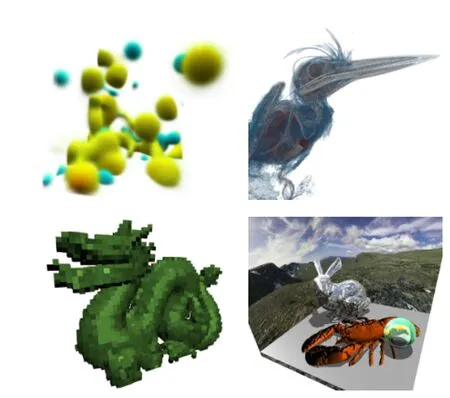
Fig.1 Example applications of our VoxLink approach:sparse volume representation of data from geostatistics and CT scans(top row),voxelized triangle meshes(bottom left),and global lighting effects for combined voxel data,implicit geometry,and volume data (bottom right).
Voxelization.The method of voxelization has long been used for voxel-based graphics systems[8]and to speed up ray tracing[9].Karabassi et al.[10]utilized the depth buffer of the GPU to voxelize non-convex objects and their surfaces.In 2000,Fang and Liao[11]presented a voxelization approach for CSG models,evaluating multiple slices along the view direction.Eisemann et al.[12]voxelized polyhedral objects in a single rendering pass on the GPU.GigaVoxels[13]is a voxel-based framework for real-time rendering of large and highly detailed volumetric scenes.These works are specialized to voxelizing either volumes or geometric objects while VoxLink can voxelize and visualize both data types. K¨ampe et al.[14]evaluated directed acyclic graphs instead of octrees to store the voxels in hierarchical levels for polygonal models.
Sparse volume rendering.Volume ray casting was first presented in 1988[15-17].In recent GPU-based approaches,the volumetric data is stored in a 3D texture and the volume rendering is performed within a single pass[18].For large,sparse datasets,naive storage often exceeds available GPU memory so advanced schemes exploiting sparsity have to be used.VDB(volumetric,dynamic grid)[19]is a framework for sparse,time-varying volumetric data that is discretized on a grid.This kind of data is used for animations and special effects in movies. Teitzel et al.[20]presented an approach to render sparse grid data by interpolating the sparse grid and in fact turning it into a volume.K¨ohler et al.[21]used adaptive hierarchical methods to render sparse volumes,effectively partitioning the whole volume into smaller volumes which are then used for volume ray casting.Gobetti et al.[22]presented an alternative single-pass approach for rendering out-of-core scalar volumes.For additional state of the art,we refer to Balsa et al.[23]and Beyer et al.[24].Other methods for storing sparse data are the compressed row storage(CRS)or compressed sparse row(CSR)patterns[25].Here,sparse matrices are compressed by removing the entries which contain zeros.Our approach adopts these notions of sparse matrices and extends it to 3D by relying on linked lists.Instead of storing all volume data,we pre-classify the volume data with a given transfer function and store only non-zero voxels.
Nießner et al.[26]used layered depth images (LDIs)[27],a concept similar to the VoxLink approach.Instead of using three orthographic projections and linked lists of voxels,they used n orthographic LDIs to store the scene's geometric data.Frey et al.[28]extended the LDI approach to volumetric depth images generating proxy data for displaying volume datasets.B¨urger et al.[29]proposed orthogonal frame buffers as an extension to LDIs to allow surface operations like recoloring or particle flow on rendered meshes.Reichl et al.[30]used a hybrid of rasterization and ray tracingtechnologies to render meshes.
3 From pixel to voxel-per-voxel linked lists
Renderingsemi-transparentscenesinasingle rendering pass is possible when employing the A-buffer approach[4].The A-buffer is aligned with the screen and each rendered fragment is stored in a list at its respective pixel location on the screen. To improve memory efficiency and account for local variations in depth complexity,ppLLs[1]can be used instead of pre-allocated memory blocks.After all fragments have been gathered in lists,the lists are sorted according to fragment depth.The final image is obtained by blending the sorted fragments based on their opacity.Since the A-buffer is created for a particular camera setting,its contents have to be updated when the view point is changed.The A-buffer also reflects the camera projection.Thus,the contents of the A-buffer describe only parts of the scene.
In contrast,we use orthographic projections along the three coordinate axes to capture the entire scene in a view-independent manner.We extend the 2D ppLL concept to per-voxel linked lists which allows us to combine the results of the three individual views in a single buffer-the VoxLink buffer.This buffer stores the voxelized scene in a memory-efficient way which can be reconstructed in the subsequent rendering step.Since the VoxLink buffer is not view-dependent,it is created in a preprocessing step(Fig.2)and has to be updated only when the scene changes.By using three orthogonal cameras we are able to rasterize the entire scene. This is due to the fact that if an object is not visible in one view,e.g.,a plane parallel to the viewing direction yields no fragments for that particular direction,it will be visible in one of the other views. Thus,the scene is fully rasterized and the final voxel volume will include each rendered fragment.Please note that the depth test is disabled to capture all depth layers of the scene.
From a conceptual point of view,we define the bounding volume with a given volume resolution to enclose the scene via an axis-aligned bounding box. One axis of the bounding volume is chosen to be the predominant axis for storing our voxel linked lists-without loss of generality let it be the z-axis. We further refer to this as VoxLink space.Using an orthographic camera along one of the major coordinate axes,we can transform each rendered fragment into VoxLink space by a simple coordinate swizzle.The bounding volume itself is subdivided into multiple bricks.For reasons of simplicity,the brick resolution is set to 1×1×1 unless otherwise noted.The voxels represent spatially extended pixels which can either be filled or empty.Our VoxLink approach only stores filled voxels by utilizing the linked-list concept.
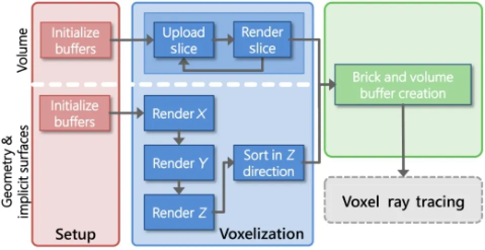
Fig.2 The pre-processing step for creating the sparse VoxLink buffer.Geometry and implicit surfaces are voxelized for each of the three coordinate axes whereas the per-voxel buffer is set up in one pass for sparse volumes.The final rendering stage is identical.
3.1Algorithm
Our VoxLink algorithm consists of two stages: pre-processing and rendering.During setup,the necessary buffers are created and initialized.For bothgeometricandvolumetricdata,asingle VoxLink buffer,i.e.,one A-buffer based on per-voxel linked lists,is sufficient.
3.1.1Geometry
Geometric objects,i.e.,mesh-based models,are voxelized in three steps.First,we render an orthographic projection of the scene for each of the major coordinate axes.During the rendering of one view,all fragments are transformed into a common coordinate system,VoxLink space,to match the predominant axis of the VoxLink buffer-the growth direction of the buffer.Each fragment is inserted into the respective per-voxel list.If a voxel entry does not exist for that position,the entry is created and added to the A-buffer,the fragment data,i.e.,surface normal and material ID,is stored,and a pointer links the entry to the fragment data.In case the entry already exists,the fragment data is appended to the fragment list of the voxel.
After rendering the scene into the VoxLink buffer,the buffer contents have to be sorted.As in the ppLL approach,each list is sorted according to depth along the predominant axis independently.
3.1.2Implicit geometry Besides rasterized polygons,voxelization can also process implicit object representations that are typically used for ray casting,e.g.,to visualize particle datasets[31].Parameters like sphere center and radius are embedded into the bounding volume and intersecting voxels are updated with a reference to the respective object[2].
3.1.3Volume data
Volume data can be transformed into a VoxLink buffer.Thevolumeisprocessedalongthe predominant axis in slices that are one voxel thick to keep the memory requirements down.On the GPU,we perform a pre-classification of the volume slice by applying the transfer function for alpha-thresholding thereby discarding transparent voxels.The remaining voxels are added to the respective voxel lists.Since the volume is sliced along the same axis we use for the VoxLink buffer,a sorting step is not necessary.The scalar value as well as the volume gradient is stored in the fragment data of each voxel.The gradient of the density volume is computed by means of central differences.The transfer function can be changed interactively by the user,affecting the data stored in the VoxLink buffer during rendering.Only if adjustments to the transfer function affect discarded data,i.e.,by assigning a non-zero opacity to previously transparent voxels,is the VoxLink buffer updated;the pre-classification is performed within 3-5 seconds.
In the last step of VoxLink buffer generation,the brick states are updated.A brick is marked as occupied if it contains at least one filled voxel. Brick occupancy is used during the rendering stage to support empty-space skipping.Note that the VoxLink buffer holds only individual non-empty bricks and information on empty space is encoded indirectly.
3.1.4Voxel ray tracing
The final rendering is obtained by voxel ray tracing within the bounding volume.Initial rays starting at the bounding volume are created for each pixel. Figure 3 shows a scene containing a semi-transparent bunny and exemplary primary rays(orange)and secondary rays(teal).A lookup in the brick volume determines whether the local area is completely empty(white cells)or whether there is a populated voxel(blue cells).In the first case,the ray can fast-forward to the next brick(indicated by dashed lines).Otherwise,each voxel within this brick has to be traversed to compute its contribution.The contribution of a voxel,i.e.,its color,is obtained by applying the transfer function to volumetric data and evaluating the illumination model using material IDs and normals for meshes and implicit geometry.
Rays are traversed by projecting the direction vector onto the voxel boundary,thereby entering the next voxel.Similarly,empty-space skipping is performed by projecting the direction vector onto the next non-empty brick.Within a brick we employ a generic ray-voxel traversal with a slight modification.Finding the next voxel along the principal direction of the VoxLink space is straight forward,i.e.,the next list element.To find a voxel in a neighboring list,we first identify the respective list and traverse it from its beginning until we arrive at the correct depth.If no stored information is available at this position,the voxel is empty and we can proceed with the next.Otherwise,the color value is computed for contributing fragments using the stored normal.The color value is then blended with the respective screen pixel utilizing front-toback blending.Secondary rays can be generated and traversed as well to achieve shadowing,reflection,or refraction.Early-ray termination is carried out once a ray leaves the bounding volume or the accumulated opacity exceeds a threshold.
4 Implementation details
We utilize the OpenGL rendering pipeline and GLSL shaders for voxelization and subsequent ray tracing. The data layout of the lists is adjusted to benefit from cache coherency during ray tracing.
4.1Data structures
Our proposed data structure is depicted in Fig.4. The top part shows the bricking of the physical space and the linked voxels.In the bottom part,the data structures and buffers are shown;these are stored in GPU memory.All links are realized as indices into particular buffers,i.e.,pointers referring to the respective linked lists.The global header,a 2D buffer,covers the front face of the bounding volume,which is perpendicular to the predominant axis. The voxels are stored in the voxel buffer as linked lists and each element consists of a fragment index,the fragment depth transformed to the predominant axis,and a pointer to the next element.
The fragment index refers to the fragment buffer,which holds material IDs and normals used for deferred shading.The material ID is used for lookup in the material buffer holding all materials.Both mesh normals and volume gradients are stored in 16 bit polar coordinates.
To support empty-space skipping,we subdivide the bounding volume of the scene into multiple bricks of size n.Each brick has a unique brick header representing n2entry indices.The combined brick headers of the first layer represent exactly the same information as the global header.Thus,the global header can be discarded during rendering.
5 Rendering
After the VoxLink buffer has been created by either voxelizing geometric objects or embedding sparse volume data,the final image is obtained by ray tracing.In the following,we point out some data-dependent peculiarities.
5.1Sparse volume rendering
Depending on the volume data and the associated transfer function,typically only a low percentage of voxels is of interest(see Table 3).All other density values can be omitted since their content is invisible,e.g.,surrounding air.
The rendering of the sparse volume data itself maps well to the proposed rendering algorithm.The main difference is,however,that changes of the transfer function are somewhat limited.Since we rely on a pre-segmentation,the transfer function can only be adjusted interactively for all densities occurring in the sparse volume.Voxels which were discarded during voxelization cannot be made visible without a re-computation of the sparse volume.
5.2Global effects rendering for geometry
With the availability of an in-memory representation of the whole scene additional global effects are feasible.Adding support for secondary rays enables shadows,refraction,and reflection.We extend the algorithm described in Section 3.1 by performing the ray traversal in a loop(see Fig.2,dashed line)and adding an additional ray buffer for dynamically managing rays generated during the rendering phase. Besides ray origin and direction,the ray buffer holds the accumulated opacity and the pixel position of the primary ray from the camera.The explicitly stored pixel position allows us to process primary and secondary rays independently of the final pixel position while contributing to the correct pixel.To account for correct blending the accumulated opacity is propagated as well.
5.2.1Opacity transport
Figure 5 depicts an opacity-value transportation scenario where voxel A is refractive as well as reflective.The refraction ray hits voxel B and thereflectionrayhits C.Thestandardcolorblending equation for front-to-back compositing is not applicable since rays can split.However,if we split the contribution of the rays and propagate the alpha value with them,the equation can be rewritten yielding the correct color as
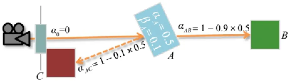
Fig.5 Correct color blending for split rays.The ray is split in voxel A and directly traversed to voxel B while the ray going to voxel C is stored for the next iteration.
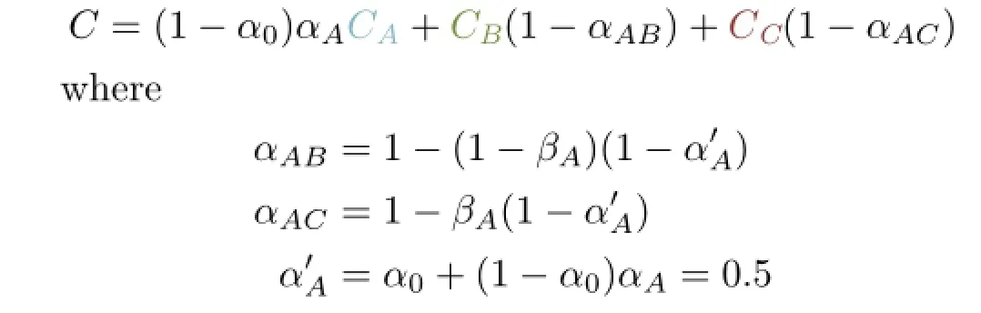
and βAdenotes the reflection coefficient of A.This principle is applied at each ray split by propagating the new opacity,and hence yields proper compositing of the final image.
5.2.2Ray traversal
The ray traversal step of the algorithm is adjusted for the iterative ray storage to take care of potential ray splits,depending on the material.Storing the rays causes memory writes using atomic counter operations and after each pass the CPU starts the next ray batch with the respective number of shaders derived from the atomic counter holding the number of active rays.If the material at the intersection point has either a reflective component or a refractive component,but not both,the current ray direction is adjusted accordingly and no split occurs.In the case of reflection and refraction,one ray is continued directly and the other is stored in the ray buffer for the next iteration.Whenever a ray hits a fragment,a new shadow ray is created which targets a light source.
To keep the shader executions from diverging too much,a ray is only iterated for a fixed number of steps n.After all rays have either finished or reached their iteration count in the current pass,only active and newly created rays are traced in the subsequent ray traversal-pass during the current frame.
6 Results and discussion
A performance evaluation was carried out on an Intel Xeon E5-2637 machine with 128GB of RAM and an NVIDIA Quadro K6000 graphics card.A viewport of size 1000×1000 was used for all measurements. The frame rates were determined by averaging the frame rates of a 360°rotation around the y-axis followed by a 360°rotation around the x-axis.With these two rotations the entire scene is covered.Since the per-voxel linked lists are generated along the z-axis,a rotation around this axis will have only minor effects on performance due to rather similar bounding volume traversals for this direction.
Figure 6 depicts the three scenes used in the evaluation.The dragon model features a nonreflective,non-refractive material.The window panes in the house scene are refractive.The bunny scene contains a refractive Stanford bunny and a reflective implicit sphere.Performance was measured for a plain rendering of the voxelized dragon and with global effects enabled for all scenes(denoted by ray tracing).Results are shown in Table 1.Please note that measurements in Table 1 include only the rendering;the one-time costs of voxelization are omitted.Information on voxelization can be found in Section 6.1.For all scenes,rendering is possible at high interactive frame rates.
To investigate the influence the view direction has on voxel traversal,we set up a scene containing a single sphere.Again,the frame rate was recorded while the scene was rotated around the y-axis and the x-axis.The results for different bounding volume resolutions as well as varying brick sizes are shown in Fig.7.Since the sphere always has the same appearance for every view direction,we can conclude that the variations are due to voxel lookup.The evaluation shows that while a brick size of 8 works best for bounding volumes of size 256 and 512,for a volume resolution of 1024,a brick size of 16 yields the best performance.All lines share the same features with slight variations.At y rotations of 90°and 270°for example,the spikes indicate the highest performance is achieved for that particular view of the scene,as this allows for the most performancefriendly traversal of the per-voxel linked lists.
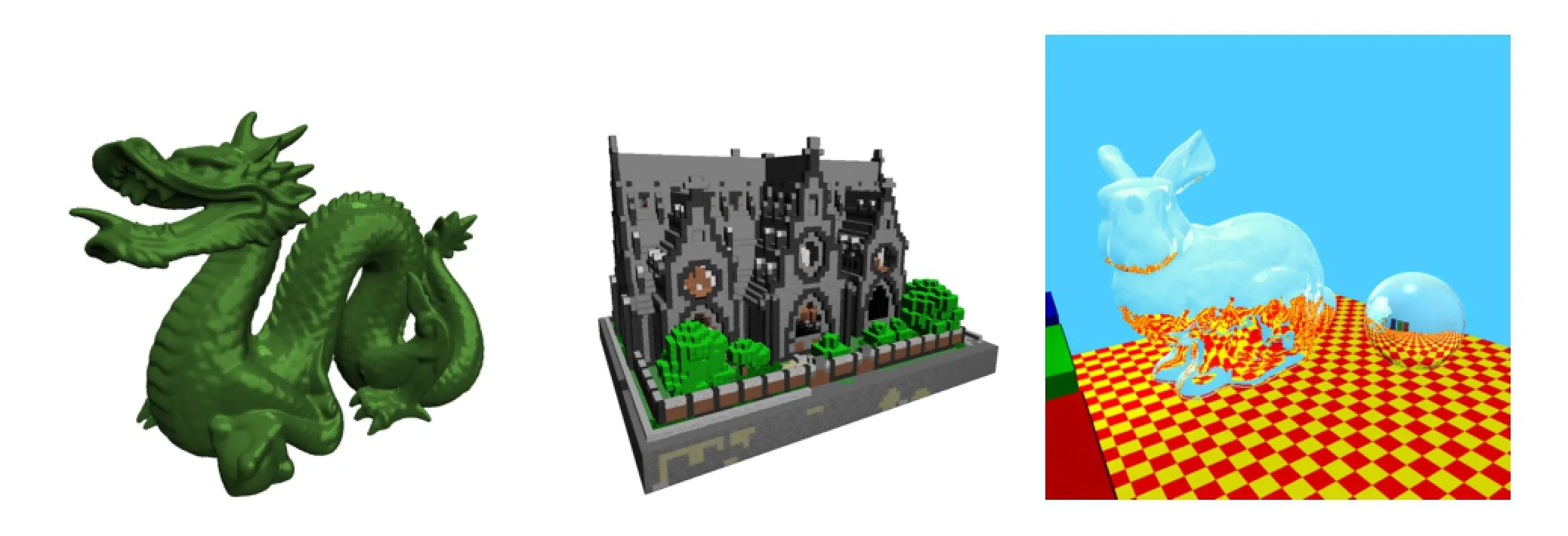
Fig.6 Dragon,house,and bunny scenes as used in the evaluation.Performance measurements are shown in Table 1.
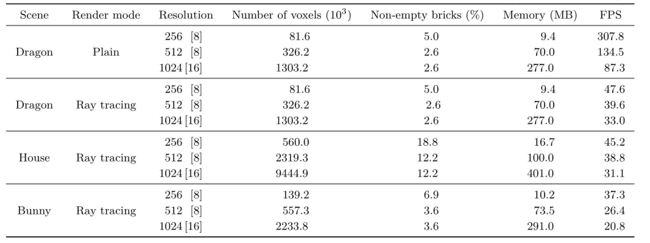
Table 1 Results of the performance measurements for our test scenes.Columns denote the resolution of the bounding volume with brick size in brackets,number of non-empty voxels,percentage of non-empty bricks,memory footprint,and frame rate(frames per second,FPS)
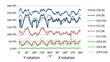
Fig.7 Ray-casted sphere rotated around the y-axis and x-axis for 360°at different bounding volume resolutions and brick sizes (denoted in brackets).
6.1Voxelization
As mentioned before,the voxelization of static scenes has to be done only once in the beginning. Ifweconsider,however,dynamicscenes,the per-voxel linked lists have to be recomputed all the time.Table 2 shows the combined results of voxelization and rendering for our three test scenes when voxelization is performed every frame.__________ This demonstrates that our approach is capable of voxelizing and rendering a scene at interactive frame rates except in the cases which combine high volume resolutions with global effects.
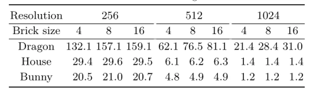
Table 2 Voxelization combined with rendering for different volume resolutions and brick sizes.Measurements given in FPS
While the approach performs well for the dragon,even for large sizes,the performance for the house and bunny scenes drops dramatically.This is due tothe high depth complexity of the scenes,particularly in the xz-plane,and the related costs for voxelization caused by axis-aligned floors and walls.In all cases,similar frame rates were obtained for brick sizes of 8 and 16.Although this seems contradictory to our findings in Fig.7 at first,the explanation is rather straightforward.The rendering process does not have too big an impact on the overall performance of one frame and the benefits of using the optimal brick size for rendering are canceled out by the additional costs of voxelization.
6.2Sparse volumes
To illustrate the applicability of our approach in combination with volume rendering,we chose two large-scale CT datasets of animals and two large datasets from the field of geostatistics.In Fig.8,the volume rendering results are shown for these datasets.The datasets are not inherently sparse by themselves,but they all contain large regions which are not of particular interest.For the CT scans of the animals(Figs.8(b)and 8(c))this applies to the air surrounding the specimen.Other volume densities representing,e.g.,tissue and bone structures are conserved and separated by applying a simple transfer function.The resolution of the animal datasets is 10243at 8 bits per data point.
Thegeostatisticsdatacomprisesavolume datasetwhichrepresentsscatteredmeasuring points interpreted into a volume dataset through a geostatistical method called Kriging[32].It is in a data-sparse format through low-rank Kronecker representations[33].A domain size of 10243and double precision were used in the simulation for computing the Kronecker volumes.We converted the data to 32 bit floating point values before voxelization and uploading into GPU memory to match our data structures.Despite the conversion no significant loss in the dynamic range could be detected when compared with the original results. Although the entire domain of the dataset actually contains data,domain experts are only interested in the data outside the 95%confidence interval of the standard deviation N(µ=0,σ2=1).This turns the volume datasets into sparsely occupied volumes.Figure 8(a)shows the data outside the confidence interval thereby illustrating the sparsity of the data itself.The depiction in Fig.1(top left),in contrast,shows the rendering of one Kronecker dataset with low opacities,generating a fluffy surface.
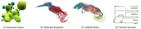
Fig.8 Datasets used in the evaluation of sparse volume rendering and their respective transfer functions.
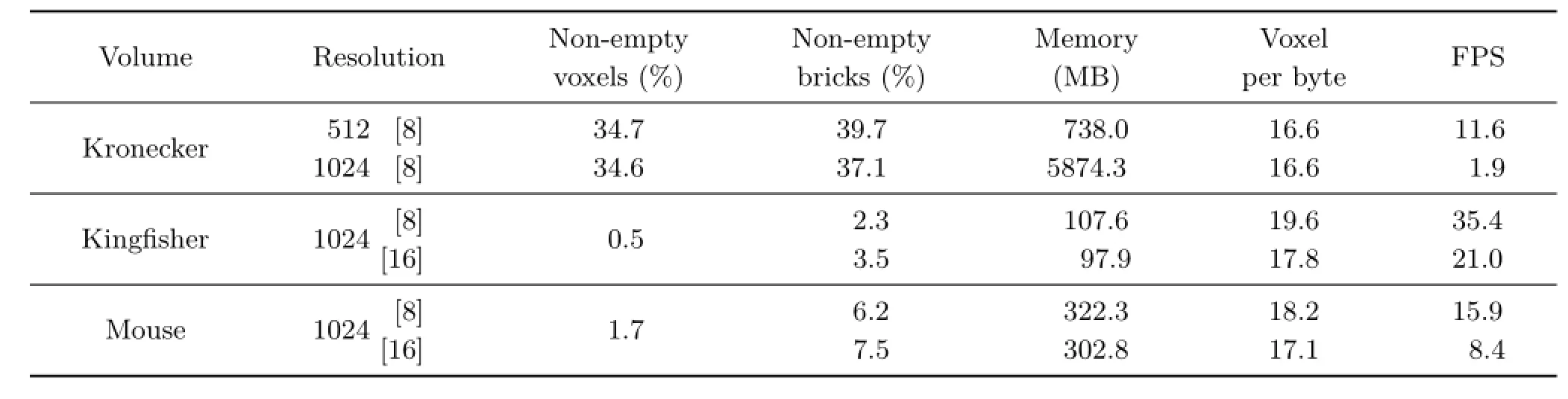
Table 3 Results for the volume datasets regarding memory usage and rendering performance.The columns denote the resolution of the bounding volume with brick size in brackets,percentage of non-empty voxels,percentage of non-empty bricks,total amount of memory,number of voxels stored per byte,and the frame rate
The generation of the per-voxel linked list is carried out on the GPU for all volume datasets as described in Section 3.1.The computation is noninteractive but takes only 2.6 s for a 10243volume dataset.Table 3 shows the results of the volumebenchmarks.The interesting parts in the Kronecker dataset still occupy a large part,34%,of the volume,resulting in a comparatively large memory footprint. The volume occupancies for the CT scans are in a range of 0.5%to 1.8%,excluding air surrounding the specimen(60%to 80%)and some of the internal tissue while keeping the main features visible.Our approach delivers interactive frame rates for most of the test cases.Naturally,higher numbers of voxels result in lower average frame rates.This also directly impacts the memory footprint but still delivers low memory footprints compared to the original dataset.
6.3Global effects rendering
In Table 1,rendering performance is shown for scenes with global effects enabled.Since the inclusion of refraction and reflection requires an additional ray buffer,the frame rate for the dragon scene drops to a mere 15%and 35%for bounding volume resolutions of 256 and 1024,respectively.At higher volume resolutions the actual costs of ray traversal outweigh the impact of the ray buffer.
With shadow rays enabled,the performance drops to about a third due to the increase in the number of rays as well as storing the shadow rays in the additional ray buffer.We also tested different upper limits n of ray steps per rendering iteration without noticing a significant difference in performance between 256,512,and 1024 steps.
6.4Distinction of existing systems
AsstatedintherelatedworkinSection2,other systems with similar capabilities have been presented before.Table 4 compares recent work in this area to VoxLink.In contrast to the other systems,VoxLink natively supports volumes and surface representations.Each system uses a different memory scheme to store the depth images or voxels.Here,we use the ppLL concept and extend it to voxels in a double layered scheme for fast empty space clipping.The octree and directed acyclic graphs used in GigaVoxels[13]and voxel DAGs[14]could be a subject for future work to incorporate in our scheme for further speed up. In contrast to the rasterization-based mechanism of VoxLink,GigaVoxels uses a direct voxelization scheme and voxel DAGs is built from sparse voxel octrees,created from depth peeling.Apart from VDI[28]which uses proxy geometry for rendering,all schemes use some sort of ray casting or ray tracing. The methods based on the orthogonal fragment buffer[29,30]also create the OFBs by rasterization and can display them via ray tracing,but can render mesh-based models only.
6.5Limitations
In its current state,our implementation has several shortcomings which are partly due to the inherent nature of voxels and partly due to unoptimized code. For voxelization,the biggest performance issue is the slow speed for updates in every frame for some scenes(see Table 2).This,however,could partly be overcome by inserting the fragments immediately into distinct bricks instead of the global buffer.Thus,only fragments in the individual bricks have to be sorted which should improve overall performance.In principle,our approach could be easily extended to handle explicit triangle meshes instead of voxelized geometry by referencing the triangle vertices per voxel but this would result in a larger memory footprint.
Another limitation is that reflection,refraction,and shadow generation for geometry relies on the voxel representation.Thus,VoxLink cannot keep up with other ray-tracing programs,e.g.,NVIDIA OptiX,either in terms of computation time or in terms of image quality.
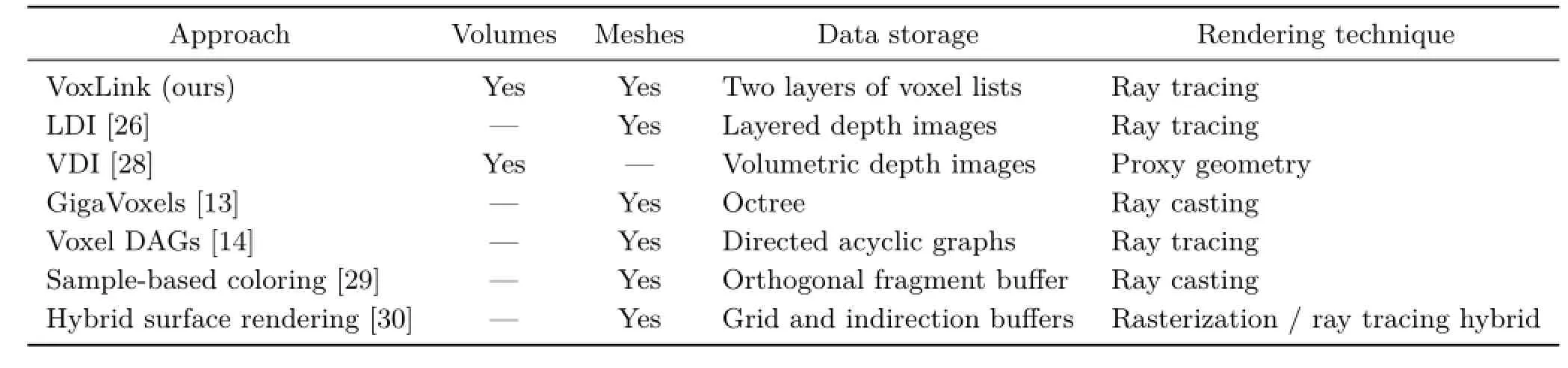
Table 4 Comparison of our VoxLink approach and similar works in terms of renderable data,storage,and rendering technique
7 Future work
For future research,we want to optimize ray traversal further by employing adaptive space subdivision methods like Octrees,BSP trees,or kd-trees instead of uniform bricks.This might also lead to a reduced memory footprint,thus making the approach more suitable for even larger volumes.Additionally,the implementation of proper level-of-detail mechanisms could improve the performance for large proxy geometries.By achieving a higher performance in the rendering phase,the number of secondary rays can be increased and,thus,enable effects like caustics,sub-surface scattering,or diffuse mirroring. The memory footprint could be reduced further by using a tighter bounding box scheme which is aligned and fitted to the sparse data,eliminating empty space within the bricks.
In their work,Kauker et al.[7]used per-pixel linked lists for distributed and remote rendering. As our approach uses similar data structures,it might be possible to also extend it to make use of multiple distributed rendering engines.As in their approach where they compared different instances of a molecule,our approach could be used for a comparison of different volumes.
8 Conclusions
In this paper,we presented VoxLink,an approach to use per-voxel linked lists for rendering sparse volume data as well as voxelization and rendering of geometry,including reflection and refraction,at interactive frame rates.Our method adapts the ppLL approach and extends it to store the entire scene in three dimensions.
Experimental results show that VoxLink reduces the memory footprint of sparse volume data while still providing interactive performance.VoxLink,to our knowledge,is the only approach that can handle arbitrary representations using voxelization.
Acknowledgements
Theenvironmentmapsusedaretheworkof Emil Persson and are licensed under the Creative CommonsAttribution3.0UnportedLicense. ThisworkispartiallyfundedbyDeutsche Forschungsgemeinschaft(DFG)as part of SFB 716 project D.3,the Excellence Center at Link¨oping and Lund in Information Technology(ELLIIT),and the Swedish e-Science Research Centre(SeRC).
References
[1]Yang,J.C.;Hensley,J.;Gr¨un,H.;Thibieroz,N.Realtime concurrent linked list construction on the GPU. Computer Graphics Forum Vol.29,No.4,1297-1304,2010.
[2]Falk,M.;Krone,M.;Ertl,T.Atomistic visualization of mesoscopic whole-cell simulations using ray-casted instancing.Computer Graphics Forum Vol.32,No.8,195-206,2013.
[3]Everitt,C.Interactiveorder-independent transparency.Technical Report.NVIDIA Corporation,2001
[4]Carpenter,L.The A-buffer,an antialiased hidden surface method.In:Proceedings of the 11th Annual Conference on Computer Graphics and Interactive Techniques,103-108,1984.
[5]Lindholm,S.;Falk,M.;Sund´en,E.;Bock,A.;Ynnerman,A.;Ropinski,T.Hybrid data visualization basedondepthcomplexityhistogramanalysis. Computer Graphics Forum Vol.34,No.1,74-85,2014.
[6]Kauker,D.;Krone,M.;Panagiotidis,A.;Reina,G.;Ertl,T.Rendering molecular surfaces using orderindependent transparency.In:Proceedings of the 13th Eurographics Symposium on Parallel Graphics and Visualization,33-40,2013.
[7]Kauker,D.;Krone,M.;Panagiotidis,A.;Reina,G.;Ertl,T.Evaluation of per-pixel linked lists for distributed rendering and comparative analysis. Computing and Visualization in Science Vol.15,No. 3,111-121,2012.
[8]Kaufman,A.;Shimony,E.3Dscan-conversion algorithms for voxel-based graphics.In:Proceedings of the 1986 Workshop on Interactive 3D Graphics,45-75,1987.
[9]Yagel,R.;Cohen,D.;Kaufman,A.Discrete ray tracing.IEEE Computer Graphics and Applications Vol.12,No.5,19-28,1992.
[10]Karabassi,E.-A.;Papaioannou,G.;Theoharis,T. Afastdepth-buffer-basedvoxelizationalgorithm. Journal of Graphics Tools Vol.4,No.4,5-10,1999.
[11]Liao,D.;Fang,S.Fast CSG voxelization by frame bufferpixelmapping.In:ProceedingsofIEEE Symposium on Volume Visualization,43-48,2000.
[12]Eisemann,E.;D´ecoret,X.Single-pass GPU solid voxelization for real-time applications.In:Proceedings of Graphics Interface,73-80,2008.
[13]Crassin,C.GigaVoxels:A voxel-based rendering pipeline for efficient exploration of large and detailed scenes.Ph.D.Thesis.Universite de Grenoble,2011.
[14]K¨ampe,V.;Sintorn,E.;Assarsson,U.High resolution sparse voxel DAGs.ACM Transactions on Graphics Vol.32,No.4,Article No.101,2013.
[15]Drebin,R.A.;Carpenter,L.;Hanrahan,P.Volume rendering.In:Proceedingsofthe15thAnnual Conference on Computer Graphics and Interactive Techniques,65-74,1988.
[16]Levoy,M.Display of surfaces from volume data.IEEE Computer Graphics and Applications Vol.8,No.3,29-37,1988.
[17]Sabella,P.A rendering algorithm for visualizing 3D scalar fields.In:Proceedings of the 15th Annual Conference on Computer Graphics and Interactive Techniques,51-58,1988.
[18]Stegmaier,S.;Strengert,M.;Klein,T.;Ertl,T.A simple and flexible volume rendering framework for graphics-hardware-based raycasting.In:Proceedings of the 4th Eurographics/IEEE VGTC Conference on Volume Graphics,187-195,2005.
[19]Museth,K.VDB:High-resolution sparse volumes with dynamic topology.ACM Transactions on Graphics Vol.32,No.3,Article No.27,2013.
[20]Teitzel,C.; Hopf,M.; Grosso,R.; Ertl,T. Volume visualization on sparse grids.Computing and Visualization in Science Vol.2,No.1,47-59,1999.
[21]K¨ahler,R.;Simon,M.;Hege,H.-C.Interactive volume rendering of large sparse datasets using adaptive mesh refinement hierarchies.IEEE Transactions on Visualization and Computer Graphics Vol.9,No.3,341-351,2003.
[22]Gobbetti,E.;Marton,F.;Guiti´an,J.A.I.A singlepass GPU ray casting framework for interactive outof-core rendering of massive volumetric datasets.The Visual Computer Vol.24,No.7,797-806,2008.
[23]Rodr´ıguez,M.B.;Gobbetti,E.;Guiti´an,J.A. I.;Makhinya,M.;Marton,F.;Pajarola,R.;Suter,S. K.State-of-the-art in compressed GPU-based direct volume rendering.Computer Graphics Forum Vol.33,No.6,77-100,2014.
[24]Beyer,J.;Hadwiger,M.;Pfister,H.A survey ofGPU-basedlarge-scalevolumevisualization. In:ProceedingsofEurographicsConferenceon Visualization,2014.Availableathttp://vcg.seas. harvard.edu/files/pfister/files/paper107camera_ready. pdf?m=1397512314.
[25]Koza,Z.;Matyka,M.;Szkoda,S.;Miroslaw,L.Compressed multirow storage format for sparse matrices on graphics processing units.SIAM Journal on Scientific Computing Vol.36,No.2,C219-C239,2014.
[26]Nießner,M.;Sch¨afer,H.;Stamminger,M.Fast indirect illumination using layered depth images.The Visual Computer Vol.26,No.6,679-686,2010.
[27]Shade,J.;Gortler,S.;He,L.-w.;Szeliski,R.Layered depth images.In:Proceedings of the 25th Annual Conference on Computer Graphics and Interactive Techniques,231-242,1998.
[28]Frey,S.;Sadlo,F.;Ertl,T.Explorable volumetric depth images from raycasting.In:Proceedings of the 26th Conference on Graphics,Patterns and Images,123-130,2013.
[29]B¨urger,K.;Kr¨uger,J.;Westermann,R.Sample-based surface coloring.IEEE Transactions on Visualization and Computer Graphics Vol.16,No.5,763-776,2010.
[30]Reichl,F.;Chajdas,M.G.;B¨urger,K.;Westermann,R.Hybridsample-basedsurfacerendering.In: Proceedings of Vision,Modelling and Visualization,47-54,2012.
[31]Reina, G.Visualizationofuncorrelatedpoint data.Ph.D.Thesis.Visualization Research Center,University of Stuttgart,2008.
[32]Kitanidis, P.K.IntroductiontoGeostatistics: Applications in Hydrogeology.Cambridge University Press,1997.
[33]Nowak,W.;Litvinenko,A.Kriging and spatial design accelerated by orders of magnitude:Combining lowrank covariance approximations with FFT-techniques. Mathematical Geosciences Vol.45,No.4,411-435,2013.
DanielKauker received his Ph.D. degree(Dr.rer.nat.)from the University of Stuttgart in 2015.His research interests are distributed computation andvisualization,genericrendering approaches,and GPU-based methods.

MartinFalkisapostdoctoral researcherintheImmersive VisualizationGroupatLink¨oping University.He received his Ph.D.degree (Dr.rer.nat.)from the University of Stuttgart in 2013.His research interests arevolumerendering,visualizations inthecontextofsystemsbiology,large spatio-temporal data,glyph-based rendering,and GPU-based simulations.
GuidoReinaisapostdoctoral researcher at the Visualization Research Center of the University of Stuttgart (VISUS).He received his Ph.D.degree in computer science(Dr.rer.nat.)in 2008 from the University of Stuttgart,Germany.His research interests include large displays,particle-based rendering,and GPU-based methods in general. A

nders Ynnerman received his Ph.D. degreeinphysicsfromGothenburg University in 1992.Since 1999 he has held a chair in scientific visualization at Link¨oping University and is the director of the Norrk¨oping Visualization Center-C.He is a member of the Swedish Royal Academy of Engineering Sciences and aboard member of the Foundation for Strategic Research. He currently chairs the Eurographics Association and is an associate editor of IEEE TVCG.His research interests include large-scale datasets in visualization and computer graphics,direct volume rendering including data reduction and volumetric lighting techniques,besides immersive visualization techniques.
Thomas Ertl is a full professor of computer science at the University of Stuttgart,Germany,and the head of the Visualization and Interactive Systems Institute(VIS)and the Visualization Research Center(VISUS).He received his M.S.degree in computer science from the University of Colorado at Boulder and Ph.D.degree in theoretical astrophysics from the University of T¨ubingen.His research interests include visualization,computer graphics,and human computer interaction.He has served on and chaired numerous committees and boards in the field.
Open AccessThe articles published in this journal aredistributedunderthetermsoftheCreative Commons Attribution 4.0 International License(http:// creativecommons.org/licenses/by/4.0/), whichpermits unrestricted use,distribution,and reproduction in any medium,provided you give appropriate credit to the original author(s)and the source,provide a link to the Creative Commons license,and indicate if changes were made.
Other papers from this open access journal are available free of charge from http://www.springer.com/journal/41095. To submit a manuscript,please go to https://www. editorialmanager.com/cvmj.
杂志排行
Computational Visual Media的其它文章
- Saliency guided local and global descriptors for effective action recognition
- An interactive approach for functional prototype recovery from a single RGBD image
- Decoding and calibration method on focused plenoptic camera
- High-resolution images based on directional fusion of gradient
- Quality measures of reconstruction filters for stereoscopic volume rendering
- Comfort-driven disparity adjustment for stereoscopic video