Reverse time migration based on normalized wavefield decomposition imaging condition
2016-07-16YUJianglongHANLiguoZHOUYanandZHANGYongsheng
YU Jianglong, HAN Liguo, ZHOU Yanand ZHANG Yongsheng
1.CollegeofGeo-ExplorationScienceandTechnology,JilinUniversity,Changchun130026,China;2.DrillingDivision,CNPCOffshoreEngineeringCorporation,Tianjin300280,China
Reverse time migration based on normalized wavefield decomposition imaging condition
YU Jianglong1, HAN Liguo1, ZHOU Yan1and ZHANG Yongsheng2
1.CollegeofGeo-ExplorationScienceandTechnology,JilinUniversity,Changchun130026,China;2.DrillingDivision,CNPCOffshoreEngineeringCorporation,Tianjin300280,China
Abstract:With the increasing complexity of prospecting objectives, reverse time migration (RTM) has attracted more and more attention due to its outstanding imaging quality. RTM is based on two-way wave equation, so it can avoid the limits of angle in traditional one-way wave equation migration, image reverse branch,prism waves and multi-reflected wave precisely and obtain accurate dynamic information. However, the huge demands for storage and computation as well as low frequency noises restrict its wide application. The normalized cross-correlation imaging conditions based on wave field decomposition are derived from traditional cross-correlation imaging condition, and it can eliminate the low-frequency noises effectively and improve the imaging resolution. The practical procedure includes separating source and receiver wave field into one-way components respectively, and conducting cross-correlation imaging condition to the post-separated wave field. In this way, the resolution and precision of the imaging result will be promoted greatly.
Key words:reverse time migration; low-frequency noises; imaging condition; wave field decomposition
1 Introduction
The research on reverse time migration began in 1980s (Whitmore, 1983; McMechan, 1983; Baysaletal.,1983; Chang & McMechan, 1986). It is based on two-way wave equation, reversely extrapolating seismic data in time domain (Zhou & Zhao, 2009). Compared with other methods, it can provide a better imaging result. When source wave fields are extrapolated, they will be saved at every time step, so reverse time migration requires a large amount of storage and computation. On the other hand, if the cross-correlation imaging condition is applied in RTM, lots of low-frequent noises will emerge in the near surface layers, which can reduce the imaging resolution. At present, there are three methods eliminating the low-frequent noises: (1) amending the wave equation, such as non-reflection acoustic wave equation (Baysaletal., 2012); (2) filtering the imaging results, such as high pass filter and Laplace filter (Guoetal.,2013; Chen & Wu, 2012); (3) improving the imaging conditions, such as Poynting vector imaging condition (Yoon & Marfurt, 2006; Wang B Letal.,2013), and wave field decomposition imaging conditions.
In order to reduce the requirement of storage, the technique of reconstruction of original wave field is applied in reverse time migration. In the process of source wave field extrapolation, the boundary wave fields are stored at every time step, the full wave fields of last two time steps are also stored. These stored wave fields will be used as boundary and initial conditions in reconstruction of original wave fields (Tang & Wang, 2012; Symes, 2007; Feng & Wang, 2012). In order to suppress the low-frequent noises, the normalized cross-correlation imaging conditions based on wave field decomposition are applied. In the process of extrapolation of source and receiver wave fields, wave fields are divided into upward wave fields and downward wave fields at every node, then these divided wave fields can be imaged respectively. Using this method, the low-frequency noises will be eliminated effectively and the imaging resolution will be improved enormously (Xuetal., 2012a; Xuetal., 2012b).
2 Reverse time extrapolation based on acoustic wave equation
2-D acoustic wave equation is as following:
(1)
Whereμis the wave field,νis the velocity.
The finite difference equation of 2-order time and 2N-order space is as following:
(2)
Where Δx and Δz are the space step lengths, Δt is the time step length,Nis half of the order numbers,iandkare the discrete point numbers in space,nis the discrete point numbers in time,cmis the differential coefficients.
Stabilization condition of Eq.(2) is:

(3)
With Perfectly matched layer (PML), some absorbing damped layers are added to the boundary of the research region, so wave fields become weaker proportionally when waves enter the absorbing damped layers, and no reflective waves arise (Berenger, 1994; Engquist & Majda, 1977; Wang W Hetal.,2013; Huetal., 2013; Yang & Wang, 2013; Wangetal., 2014).
The governing equation of perfectly matched layer is:

(4)
WhereA(x,z) is the absorbing damped factor.
The high-order finite difference equation based on PML is:
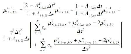
(5)
Use cosine damped factor:
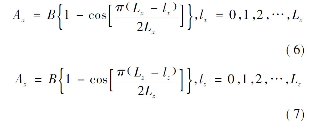
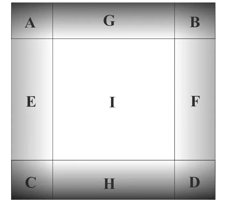
Fig.1 Sketch of perfectly matched layer
WhereAxandAzare the damped factors atxandz, respectively;Bis the damped range factor,B=300;LxandLzare the lengths of layers at x and z, respectively. In Fig.1, the damped factor isAx+Azin A, B, C and D;Ax= 0,Az> 0in G, H;Az= 0,Ax> 0 in E, F.
3Traditional imaging conditions
There are three imaging conditions in reverse time migration: excitation time imaging condition, cross-correlation imaging condition and the amplitude ratio of upgoing and downgoing waves imaging condition. Excitation time imaging condition includes storing the first-arrival travel time as the imaging time of every node, then the amplitude of receiver wave field extrapolations at the imaging time is the value of the node (Tianetal.,2002; Wangetal., 1999; Liu, 1993; Wangetal.,1997; Schneideretal., 2012; Zhangetal., 2006; Asakawa, 1993; Chang & McMechan, 1986). Because of the difficulty of obtaining the accurate travel time, excitation time imaging condition needs much more researches. Currently, cross-correlation imaging condition is the most popular imaging condition, it does not need to store the first-arrival travel time, its equation is:
(8)
Where Image(x,z) is the imaging value,μs(x,z,t) is the source wave field,μr(x,z,t) is the recei-ver wave field, the value at every node equals to the sum of the zero-lag cross-correlation between source wave field and receiver wave field at time step (Kaelin & Guitton, 2006; Chattopadyay & McMechan, 2008; Zhang & Sun, 2009). In order to get the more accurate migration results, the source-normalized cross-correlation imaging condition is presented (Changetal., 2014; Qin & McGarry, 2013). The equation is:
(9)
4Imaging condition based on wave decomposition
When the angle between source wave field vector and recei-ver wave field vector is large, the low-frequencies noises will emerge. Because RTM takes advantage of two-way wave equation, when source wave field and receiver wave field meet with impedance interface, they will be divided into downgoing wave and upgoing wave, respectively. The cross-correlation imaging condition includes:
(1) the cross-correlation between the downgoing wave of source wave field and downgoing wave of receiver wave field;
(2) the cross-correlation between downgoing wave of source wave field and upgoing wave of recei-ver wave field;
(3) the cross-correlation between upgoing wave of source wave field and downgoing wave of receiver wave field;
(4) the cross-correlation between upgoing wave of source wave field and upgoing wave of receiver wave field.
Where conditions (1) and (2) are the expected results, because the angle between source wave field vector and receiver wave field is small, conditions (3) and (4) are the low-frequent noises (Duetal.,2013).
Using wave field decomposition imaging condition, the wave field is divided into upgoing wave and downgoing wave at each underground reflective point.
S(x,z)=Sd(x,z)+Su(x,z)
(10)
R(x,z)=Rd(x,z)+Ru(x,z)
(11)
WhereS(x,z) andR(x,z) are the source wave field and the receiver wave field, respectively, subscriptddenotes the downgoing wave field, subscriptudenotes the upgoing wave field. The cross-correlation imaging condition is performed between conditions (1) and (2):
(12)
In order to improve the precision, Eq.(12)becomes:
(13)
Where
Su(x,z)=FFT-1{S+(t,kz)}

(a) Downgoing and upgoing wave of sources wavefield;(b) downgoing and upgoing wave of receiverswavefield.Fig.2 Sketch of wave propagation of source and receiver wavefield in RTM
(14)
(15)

Source wave field normalization:
(16)
Receiver wave field normalization:
(17)
5 Examples
In order to validate the efficiency of this method, horizontally layered model and complex Marmousi model are tested respectively.
5.1Horizontally layered model
Fig.3 is the simple horizontally layered model with size 350×500. The velocities of three layers are 1 500 m/s, 2 000 m/s and 2 500 m/s, respectively. Fig.4 is the RTM result of middle-excitated single shot recording. The recording time is 2.5 s and the number of receivers is 381.
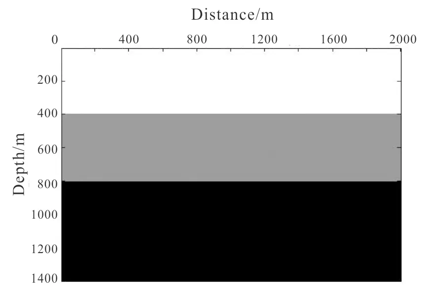
Fig.3 Horizontally layered model
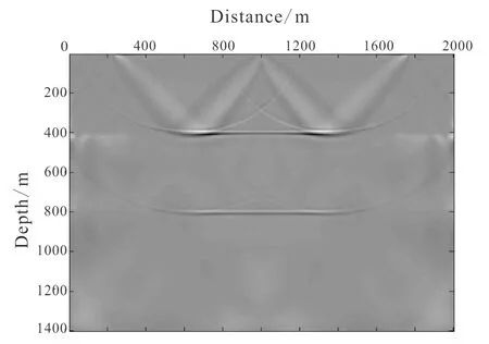
Fig.4 Result of RTM on horizontally layered model
Fig.4 is the result of RTM on horizontally layered model by using conventional source-normalized cross-correlation imaging condition. Fig.5 is the result of RTM on horizontally layered model by using source-normalized and receiver-normalized cross-correlation imaging conditions based on wave field decomposition. In Fig.4, there are some obvious low-frequent noises in the shallow layers, which will disturb the imaging resolution severely. In Fig.5, source-norma-lized and receiver-normalized cross-correlation imaging conditions based on wave field decomposition are applied in reverse time migration. The low-frequency noises in the shallow layers are suppressed to some extent, and the resolution is advanced. It is meaningful for complicated structure imaging.

(a) Result of RTM with source-normalized cross-correlation imaging condition based on wave field decomposition; (b) result of RTM with receiver-normalized cross-correlation imaging condition based on wave field decomposition.Fig.5 Results of RTM on horizontally layered model
5.2Marmousi model
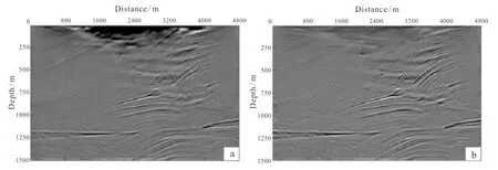
Fig.6 is the Marmousi mode with size 300×600. The horizontal sampling length is 8 m, and the vertical sampling length is 5 m. The time sampling length is 0.5 ms and the recording time is 3.5 s. The number of shots is 119 and the number of receivers is 561. We use the finite difference equation of 2-order time and 16-order space to carry out reverse time migration. Fig.7 is the result of reverse time migration by using conventional source-normalized cross-correlation imaging condition, and Fig. 8 is the results of reverse time migration by using source-normalized and receiver-normalized cross-correlation imaging conditions based on wave field decomposition.
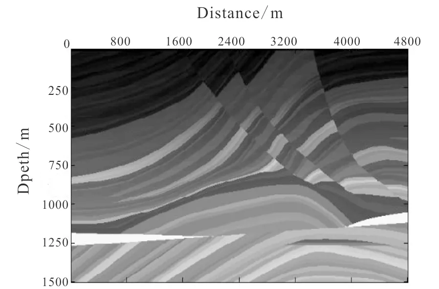
Fig.6 Marmousi model
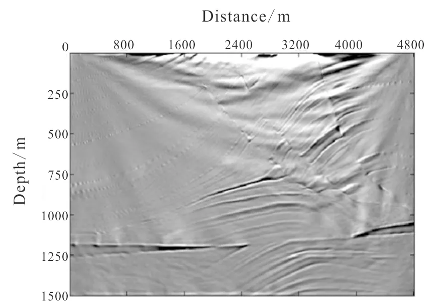
Fig.7 RTM result on Marmousi model
In Fig.7, there are lots of low-frequent noises in the shallow layers, and these noises affect the precision severely. In Fig.8a, the shallow low-frequent noises are suppressed effectively, and faults and other complex structures become clearer in the imaging result. In Fig.8b, the noises in the near surface layers are suppressed mostly, structures in the near surface layers become much clearer, the resolution is also advanced greatly.
6Conclusions
More and more attentions are paid to reverse time migration because of its advantages of imaging high dip angle structures and other complex models. However the low-frequent noises in the near surface limit its industrial application. Source-normalized and receiver-normalized cross-correlation imaging conditions based on wave field decomposition are able to suppress the shallow low-frequency noises effectively, and improve the imaging precision which is important to image complex structures. Because single filtering method could not suppress the low-frequent noises effectively, the combination of multiple filtering metho-ds should be thought seriously in the future research.
(a) Result of RTM with source-normalized cross-correlation imaging condition based on wave field decomposition;(b) result of RTM with receiver-normalized cross-correlation imaging condition based on wave field decomposition.Fig.8 Results of RTM on Marmousi model
References
Asakawa E. 1-993. The interpolation in travel time of seismic ray tracing.OilGeophysicalProspectingTranslationCollections, (4):1-9.
Baysal E, Kosloff D D, Sherwood J W C. 2012. A two-way nonreflecting wave equation.Geophysics, 49(2): 132-141.
Baysal E, Kosloff D D, Sherwood J W C. 1983. Reverse time migration.Geophysics, 48(11): 1514-1524.
Berenger J P. 1994. A perfectly matched layer for the absorption of electromagnetic waves.JournalofComputationPhysics, 114(2): 185-200.
Chattopadhyay S, McMechan G A. 2008. Imaging condition for prestack reverse time migration.Geophysics, 73(3): 81-89.
Chang H M, He B S, Yang J J,etal. 2014. The normalization weighting cross-correlation imaging condition in reverse time migration.CoalGeologyofChina, 26(1):51-55. (in Chinese with English abstract)
Chang W F, McMechan G A. 1986. Reverse time migration of offset vertical seismic profiling data using the excitation time imaging condition.Geophysics, 51(1): 67-84.Chen K, Wu G C. 2012. Reverse time migration Laplacian ope-rator filtering modification algorithm.OilGeophysicalProspecting, 47(2): 249-255. (in Chinese with English abstract)
Du Q Z, Zhu Y T, Zhang M Q,etal. 2013. The strategic research in elimination of low-frequent noises of prestack reverse time migration.Geophysics, 56(7): 2391-2401.(in Chinese with English abstract)
Engquist B B, Majda A. 1977. Absorbing boundary conditions for the numerical simulation of waves.MathematicsofComputation, 31(1): 629-651.
Feng B, Wang H Z. 2012. Reverse time migration with source wavefield reconstruction strategy.JournalofGeophysicsandEngineering, 9(1): 69-74.
Guo N M, Feng X M, Li H S. 2013. High-order Laplacian operator method in the elimination of RTM low-frequent noise.GeophysicalProspectingforPetroleum, 52(6): 642-649. (in Chinese with English abstract)
Hu h, Liu Y K, Chang X,etal. 2013. Analysis and application of boundary treatment for the computation of reverse time migration.ChineseJournalofGeophysics, 56(6): 2033-2042. (in Chinese with English abstract)
Kaelin B, Guitton A. 2006. Imaging condition for reverse time migration//SEG Technical Program Expanded Abstracts, 25(1): 2594-2598.
Liu Q L. 1993. Ray tracing in seismic first arrival wave.GeophysicalProspectingforPetroleum, 32(2): 14-20.(in Chinese with English abstract)
McMechan G A.1983. Migration by extrapolation of time dependent boundary values.GeophysicalProspecting, 31(3): 413-420.
Qin T L, McGarry R. 2013. True amplitude common shot acoustic reverse time migration//SEG Technical Program Expanded Abstracts, 52-58.
Schneider W A, Ranzinger K A, Balch A H,etal. 2012. A dynamic programming approach to first arrival travel time computation in media with arbitrarily distributed velocities.Geophysics, 57(1): 39-50.
Symes W W. 2007. Reverse time migration with optimal checkpointing.Geophysics, 72(5): 213-221.
Tang C, Wang D L. 2012. Reverse time migration based on wave field reconstruction and wave field decompostion.GlobalGeology, 31(4): 803-811.(in Chinese with English abstract)
Tian X F, Zhang F X, Cao X L. 2002. Elastic wave reverse time migration and imaging condition.CoalGeologyofChina, 14(2): 58-61. (in Chinese with English abstract)
Wang B L, Gao J H, Chen W C,etal. 2013. Extracting efficiently angle gathers using Poynting vector during reverse time migration.Geophysics, 56(1): 262-268.(in Chinese with English abstract)
Wang W H, Ke X, Pei J Y. 2013. Application investigation of perfectly matched layers absorbing boundary condition.ProgressinGeophysics, 28(5): 2508-2514.(in Chinese with English abstract)
Wang H Z, Xie H B, Ma Z T. 1997. The computation of seismic wave travel time using finite difference.JournalofTongjiUniversity, 25(3): 318-321.(in Chinese with English abstract)
Wang H Z, Fang Z M, Xu Z T,etal. 1999. The computation of seismic wave travelling time.OilGeophysicalProspecting, 34(2): 155-163.(in Chinese with English abstract)
Wang K Y, Zhou Y, Liu D,etal. 2014. Absorbing boundary condition in finite difference wave equation forward mode-ling simulation.ContemporaryChemicalIndustry, 43(5): 752-755.(in Chinese with English abstract)
Whitmore N D.1983.Iterative depth migration by backward time propagation//SEG Technical Program Expanded Abstracts, 382-385.
Xu X R, Wang X W, Wang Y C,etal. 2012a. Study and application of imaging condition for reverse time migration based on wave fields separation.ProgressinGeophysics, 27(5): 2084-2090. (in Chinese with English abstract)
Xu X R, Wang Y C, Hu Z D,etal. 2012b. Wave field separation based reverse time migration imaging condition and its application in Junggar basin.NaturalGasGeoscience, 23(3): 602-606. (in Chinese with English abstract)
Yang H X, Wang H X. 2013. A study of damping factors in perfectly matched layers for the numerical simulation.AppliedGeophysics, 10(1): 63-70. (in Chinese with English abstract)
Yoon K, Marfurt K J. 2006. Reverse time migration using the Poyting vector.ExplorationGeophysics, 37(1):102-107.
Zhang M G, Cheng B J, Li X F,etal. 2006. A fast algorithm of shortest path ray tracing.ChineseJournalofGeophy-sics, 49(5): 1467-1474.(in Chinese with English abstract)
Zhang Y, Sun J. 2009. Practical issues in reverse time migration: true amplitude gathers, noise removal and harmonic source encoding. http://www.cgg.com/technicalDocuments/cggv_0000002133.pdfZhou R H, Zhao J X.2009. Reverse-time migration and its ima-ging conditions.InnerMongoliaPetrochemicalIndustry, (3):23-26. (in Chinese with English abstract)
doi:10.3969/j.issn.1673-9736.2016.02.05
Article ID: 1673-9736(2016)02-0095-07
Received 23 October 2015, accepted 2 December 2015
杂志排行
Global Geology的其它文章
- Geochronology and geochemistry of Dongxigao diorite porphyries: implications for Late Neoarchean tectonic evolution of eastern North China Craton
- Genesis of lower strain S-L-type tectonites in Daqingshan area, Inner Mongolia
- Petrogenesis of Paleoproterozoic diorite porphyries in Luojiazhuang, western Shandong: constraints from LA-ICP-MS zircon U-Pb geochronology and geochemistry
- Comparison of finite difference and pseudo-spectral methods in forward modelling based on metal ore model of random media
- Study of formation boundary and dip attribute extraction based on edge detection technology
- Subsurface sandstone mapping by combination of GPR and ERT method
