Developments in the understanding of gas-solid contact efficiency in the circulating fluidized bed riser reactor:A review☆
2016-05-29ChengxiuWangJesseZhu
Chengxiu Wang ,Jesse Zhu ,2,*
1 State Key Laboratory of Heavy Oil Processing,China University of Petroleum,Beijing 102249,China
2 Department of Chemical&Biochemical Engineering,The University of Western Ontario,London,Ontario N6A 5B9,Canada
1.Introduction
Fluidization is a process which involves the flow of solid particles in contact with liquid,gas,or both gas-liquid flow.Regimes for gas-solid fluidization may include particulate,bubbling,slugging(abnormal state),turbulent,fast fluidization and pneumatic transport[1,2].In a fast fluidized bed,solids must be continuously fed into the bed(the riser)at or near the bottom and the entrained solidsby the high velocity gas flow are captured at the top and sent back to the bottom of the riser through a recirculation system outside of the riser to maintain an“uninterrupted”solid circulation.Therefore,the fast fluidization and the corresponding fast fluidized bed was referred to as“continuous fluidization”and “circulating fluidized bed”,respectively[3,4].Bene fits of circulating fluidized bed reactors include significantly reduced gas and solid backmixing,improved contact efficiency,and continuous process coupled with higher product capability[3-5].
Industrial applications of circulating fluidized beds(CFBs)started in the 1950s[6],and rapidly expanded in the last five decades.It is clear to see that tw o main w aves of tremendous developments of CFBs associated with fluid catalytic cracking(FCC)and circulating fluidized bed combustion(CFBC).As discussed by Zhu and Bi[7],there are many distinctive differences in the operating conditions of these two industrial processes.Somekey differences are listed in Table 1.It shows that typical FCCunitsoperateat agasvelocity ranging from 6 to 28 m·s-1and asolid circulation rate(Gs)of 400-1200 kg·m-2·s-1,while typical CFBC reactors operate at low er gas velocity from 5 to 9 m·s-1and much lower Gsfrom 10 to 100 kg·m-2·s-1,resulting in much lower solid holdup in CFBC reactors.Moreover,bed geometry,solid inventory and solid feeding device are also significantly different between FCC and CFBC.

Table 1 Typical operating conditions of FCC and CFBC units[7]
In reviewing the research history,the earlier reported studies throughout the 1970s to early 1990s almost entirely focused on hydrodynamics of CFBs operating with low solid circulation rate of 100 kg·m-2·s-1concentrating on operating conditions used for CFB coal combustion while little research was published for the FCC riser except for an earlier report from Shell[8].Previous experiments have clearly demonstrated that a CFB reactor with low solid flux is hydrodynamically characterized by an extremely non-uniform flow structure,with a dense bottom region and dilute upper region in the axial direction[9,10]and a ‘core-annulus’ flow structure in the radial direction[2,11].This non-uniform flow structure and the relatively dilute solid concentration(usually less than 10%)result in many disadvantages,such as serious gas by-passing through the core dilute region and extensive back mixing of solids in the wall region,consequently resulting in lower gross gas solid contact efficiency and poor selectivity of chemical reactions[12,13].Also,there are a reduction in heat transfer coefficients between heat transfer surfaces and suspension and somewhat greater temperature gradient than in dense beds[4,11].These limitations as suggested by the previous researchers greatly affect the application of CFBs'to processes with slow reaction rates or requiring high heat transfer rates.
To raise the attention of the CFB working community,Bi and Zhu[14]proposed the concept of HDCFB/HFCFB(high density/ flux circulating fluidized bed)in contrast to LDCFB/LFCFB(low density/ flux circulating fluidized bed).It was pointed out that although many commercial CFB setups are operating under high density conditions such as FCC,majority of the fundamental studies had been carried out in relatively low density circulating fluidized beds(LDCFB)and there had been little reported fundamental effort on the high density circulating fluidized bed(HDCFB).Such high density includes both high flux and high holdup with the criterion of solid circulation rate reaching 200 kg·m-2·s-1and the average solid holdup of 10%as the boundary to demarcate the tw o conditions[15,16].
Studies on HDCFB were first carried out in the late 1990s.Recently,high density circulating fluidized beds have become one of the focal points in the field of CFB systems.[10,16-18]Numerous studies under high solid flux have shown that the hydrodynamics are quite different in comparison with low flux and low density CFB risers operated with Gs< 200 kg·m-2·s-1[15,19-25].Fig.1 show s a typical flow structure in high density circulating fluidized bed.Some key findings include:
(1)In the axial direction,the average solid holdup for HDCFB is up to 10%-30%with the densest solid holdup up to almost 40%at the bottom section of the riser,much higher than LDCFB with solid holdup usually lower than 1%in the developed region.In addition,a fairly uniform axial pro files of solid holdup is achieved across the w hole bed under extremely high solid circulation rate of 1000 kg·m-2·s-1,at higher solid holdup.
(2)In the radial direction,local solid concentration under HDCFB is also much higher than that under LDCFB.As show n in Fig.1,the radial solid distribution becomes steeper with higher flux.Work by other researchers[27]also show ed that the dow n flow of particles in the wall region almost disappeared under high density conditions leading to a reduction of axial gas dispersion under HDCFB.Based on the securrent studies,it can beconcluded that in HDCFB reactors,more favorite hydrodynamics with high solid flow rates and more uniform dense suspension along the axial direction may result in improved reactor performance with better gas-solid contacting efficiency and higher conversion per unit volume and will be very useful for applicationsre quiring higher solid/gas feed ratios and uniform solids and gas residence time,and processes where high gas-solid contacting efficiency is crucial[28,29].The contact efficiency between gas and solids is closely related to the hydrodynamics and mass and heat transfer behaviors in the CFB reactor,and it has a significant influence on the overall system performance.
Until now,most of the research concentrate on hydrodynamics as summarized by several authors.While several hundreds of papers have been published on the hydrodynamics of fluidized beds,few er results(all summarized in Table 2)have been reported on the gas solid contacting.The contact efficiency of gas-solid in acirculating fluidized bed is not well understood,partially due to measurement difficulties and the lack of a rigorous definition for the contact efficiency.A clear understanding of the gas-solid contacting will help in the design of CFB reactors.This paper attempts to present efforts made in developing fundamental understanding of gas-solid contact efficiency in CFB reactors,especially in HDCFB reactors.
2.Experimental Testing Methods
In a general sense,contact efficiency is related to gas bypassing due to the nonuniform structure especially the nonuniform flow structure in the radial direction in both LDCFB and HDCFB reactors.As described by Dry et al.[12],in a CFB reactor,not all the gas fed into the reactor would come into close contact with the solids:some of the reactant gas would experience intimate contact with the dispersed particles,and some may emerge at the outlet of the reactor without having made substantial contact with any solidsat all.Of the gas which does come in to close contact with the solids,a fraction would be converted and the rest would exhaust unchanged.The contact efficiency then can be defined based on the conversion of aspecial speciesunder carefully chosen conditions.Gas-phase conversion measured across there actor would re flect acombination of hydrodynamic and reaction behaviors.The technique developed so far for measuring the contact efficiency can be divided into two categories:the indirect method using gas-solid heat transfer testing and the direct method using catalytic ozone decomposition as a model reaction,as show n in Table 2.
The former is a reasonable w ay because heat transfer is largely controlled by the gas and solid contacting behavior.The results of heat transfer between gas and solids can be used to characterize the gassolid contacting efficiency and the mass transfer performance.Therefore,earlier studies on contact efficiency were almost all conducted using heat loss from a pulse of hot gas[12,34,38].Typical apparatus and the testing probe is schematized in Fig.2 and detailed information can be found in the related papers.
The latter is more attractive because it employs real chemical reaction to evaluate the reactant conversion in CFBs and the chemical reaction itself can supply direct information on reactor performance.A carefully chosen chemical reaction is the key success for this method.Because of its simplicity in reaction kinetics(very close to first-order reaction),negligible heat effect of reaction due to the low concentrations involved,and the availability of a simple and accurate measurement method,a heterogeneous catalytic reaction—ozone decomposition catalyzed by ferric oxide—was very often employed as a model reaction to investigate reaction coupled with mass transfer in fluidized bed reactors[30,36].Atypical ozonegeneration and measurement system is shown in Fig.3.The underlying theory was elaborated by Ouyang et al.[45]and Li et al.[41].
3.Contact efficiency by Heat Transfer Measurement Method
3.1.Definition of gas-solid contact efficiency
For the heat transfer method,gas temperatures were usually measured by a rapid-response thermocouple.Assuming that the heat loss to the CFB w all can be negligible,an energy balance across a given section of the reactor gives:
Heat loss from the gas stream=Heat transferred to the solids phase (1)

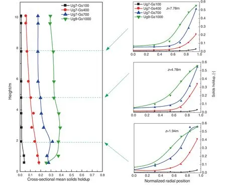
Fig.1.Characteristics of flow structure at extremely high flux/density conditions[26].
w here cpgis the specific heat of gas,ρgis the gas density,A is the crosssection area of the bed,Tg,1is the gas temperature at the top of a given riser and Tg,2is the gas temperature at the bottom of a given bed section,hgsis the heat transfer coefficient between gas and solids,α is the surface to volume ratio of a particle,is the average gas temperatureis the average solid temperature and ΔZ is the height of a given bed section.Rearranging the above equation gives:
The left hand side of the above equation is then the “driving force”for interfacial heat transfer.Considering the analogy between heat and mass transfer,the same driving force can also be used to characterize gas-solid mixing.Based on the above,the contact efficiency between the gas and solids is defined as:


Table 2 Facility description for contact efficiency experiments
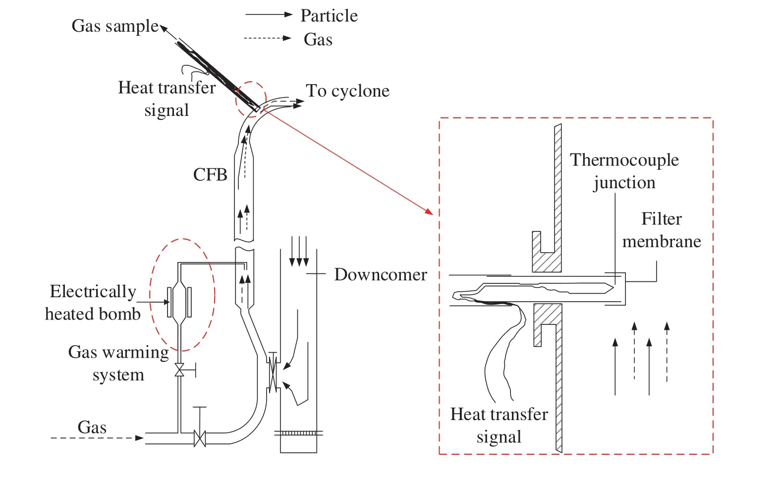
Fig.2.Schematic of the designs of the heat transfer measurement technique[12].

Fig.3.Schematic of the designs of the ozone decomposition measurement[41,42].
3.2.Key results of contact efficiency by heat transfer measurements
One of the tw o plenary lectures on the heat transfer measurement were delivered by Dry et al.[12,34].The most striking results of their work conducted in a CFB riser of 0.09 mm i.d.with 7.2 m high are shown in Fig.4.
The magnitude of the contact efficiency is from 0.01%to 0.18%.The trends in Fig.4(a)with gas velocity and solid circulation rate suggest that an increase in solid holdup is associated with a less contact efficiency.This seems reasonable since the effects of particle aggregation would be expected to strengthen as solid circulation rate increases and the aggregated particles are likely to provide less effective surface area to the main reactant gas stream.Pro files of the contact efficiency v.s.solid holdup are shown in Fig.4(b)and the conclusions are generally the same for Fig.4(a),as might be anticipated.To investigate the particle-size/aggregation effects on the reactor performance,Dry et al.[34]extended their research to study the effect of particle size on gas solid contact in CFBs using heat transfer measurement.
Fig.5 shows the contact efficiency for three kinds of solid particles.As noted in this figure,the magnitude of these efficiencies is low,0.03%-3%.In all cases,contact efficiency decreases as solid holdup increases.Contact efficiency is also lower at lower superficial gas velocity.This is reasonable in terms of lower turbulence magnitudes permitting higher degrees of aggregate formation and hence greater levels of shielding.Compared to the results with different particle size distributions,the overall trend is clear:the coarser the solids the more surface-efficient it becomes through less participation in aggregated cluster formation.Dry et al.[34]mentioned that this is analogous to bubbling beds showing improved gas-solid contact as coarser particles are used—the permeability of the dense phase increases as particle size increases,leading to more“slow”bubbles and higher contact efficiency(above a certain particle size limit).In the CFB case it appears that this trend is mirrored,with coarser particles leading to more permeable clusters and(hence)greater surface efficiency.

Fig.4.Typical results of contact efficiency in the CFB riser[12].

Fig.5.Effects of particle size on gas-solid contact efficiency[34].
4.Contact efficiency by Catalytic Ozone Decomposition Reaction
As mentioned in Section 2,the catalytic decomposition of ozone in a CFB reactor can directly provide information on reactor performance and therefore,recent research on gas-solid contacting and mixing usually employs this “hot-model”method.Compared to the indirect heat transfer measurement discussed above,using ozone decomposition reaction can easily map a detailed distribution of ozone concentration at each position,both axially and radially in the CFB reactor.
4.1.Axial distribution of ozone concentration
Ouyang et al.[36]comprehensively investigated the ozone decomposition in a CFB riser and obtained the axial ozone concentration profiles at different radial positions under different operating conditions as shown in Fig.6.Ozone concentrations in all figures are presented in the form of“dimensionless concentration”which is defined by dividing the actual ozone concentration by initial concentration at the riser inlet.

Fig.6.Typical axial pro file of ozone concentration in the CFB riser[36].
The data suggest that there exists a strong axial gas and solid mixing flow in the riser reactor from flatness of the axial ozone concentration pro file in the fully developed region.They also show that the ozone concentrations at all radial positions increase to a maximum because of influences of the gas and solid mixing within the entrance acceleration zone.In addition,internally recycling catalyst and the externally circulating catalyst stream merge with fluidization gas stream at the bottom dense region and result in torrent gas-solid flow.This indicates that a dense layer of solids may happen near the w all forming an annuluscore pattern.
4.2.Radial distribution of ozone concentration
Typical experimental results are shown in Fig.7,which depicts the radial ozone concentrations pro files at three different axial positions presented in two papers,i.e.,Ouyang et al.[36]and Schoenfelder et al.[37].

Fig.7.Typical radial pro file of ozone concentration in the CFB rise[36,37].
As show n in the figure,ozone concentration is different at different radial positions:the concentration in the central region is much higher than that in the near w all region.The suggested reason for such a radial concentration pro file in the CFB riser is that in the w all region higher solid holdup results in higher reaction rates as compared to those in the dilute core region[46].The ozone concentration difference between the core and w all regions decreases with an increase in the axial position,which corresponds to a decrease in solid holdup.These data indicate that the trend of the radial ozone concentration pro files is essentially dominated by the flow structure,which is represented by the axial and radial solid holdup pro files,showing strong correlation between flow structure and local conversion.
From the above discussion,it is clear to see that the distribution of ozone concentration is nonuniform in the radial distribution resulting from the nonuniform solid flow across the cross-section of the CFB system.To homogenize radial variations and improve gas-solid interphase contact,Jiang et al.[32]installed the effect of baffles,to study their effect on the radial ozone concentration pro file,with introducing four ring-type baffles located at 1.08,2.39,3.60,4.82 m above the distributor in their 0.102 m diameter and 6.32 m high CFB riser.Radial ozone concentration pro files inside the riser are show n in Fig.8.When compared with those without baffles,for a similar gas velocity and solid circulation rate,the radial ozone concentration pro files at all five axial locations are flatter.For a reactor system with baffles,the lateral mixing of gas and the downward flow of solids in the w all region enhances the solid exchange between the w all region and the core region,thus reducing the recirculation of gas reactant,which is either adsorbed on the catalyst or entrained in clusters.Therefore,the contact between the reactant and catalyst solidscan beenhanced.Whereas,in a system without baffles,solid holdups are higher in the w all region and lower in the center region,givingparabolic ozone concentration pro files at different axial heights,which persist over the entire height of the riser[32].

Fig.8.Effects of baffles on ozone concentration in the CFB riser[32].
4.3.Ozone distribution pro files in the HDCFB riser
The above section shows the ozone distribution in CFBs most of which were obtained in LDCFB with low solid flux of less than 200 kg·m-2·s-1.To investigate the ozone decomposition in HDCFB reactor,Zhu's research group put much effort to systematically carry out experiments to examine the gas-solid mixing and contacting in HDCFB reactors[29,43,44,47-49].Most recently,Wang et al.[43,44,47]completed are search with high solid circulation rate up to 800 kg·m-2·s-1.
The axial ozone concentration pro files with the corresponding solid holdup pro files under different operating conditions in the riser are show n in Fig.9.It is show n that the ozone concentration always decreases with increasing distance from the distributor.For all the operating conditions,the axial distribution pro files of the ozone concentration have a similar trend:except for the entrance region of the column where the ozone concentration decreases quickly,the ozone concentrations change more gradually and even have almost no change along the axial elevations.
In addition,there is a clear difference in the axial distributions of ozone concentration between low and high solid concentrations.When Gsis low(Gs=100 kg·m-2·s-1),the axial pro files has a more uniform axial distribution with a very short entrance-section(less than 2 m)w here the ozone concentration drops sharply.Above this region,the ozone concentration remains relatively constant.When Gsis higher than 200 kg·m-2·s-1,the dramatic decrease of ozone concentration covers much longer length which can be up to 6 m for Gsof 800 kg·m-2·s-1,leading to higher ozone conversion.The obvious reason is that the average solid holdup is much higher for high solid flux conditions than that for low solid flux cases.Under high solid concentration conditions,there would be more opportunity of contacting between gas and solids so that the reactant can be converted as much as possible.It can also be seen that low superficial gas velocities and/or high solid circulation rates lead to low ozone concentration(i.e.high ozone conversion)and vice versa which is similar to the results reported by Jiang et al.[32]in the LDCFB riser discussed in the above sections.
Typical radial distribution pro files of the ozone concentration at different axial positions under Ugof 7 m·s-1and Gsof 300 and 700 kg·m-2·s-1in the riser column are show n in Fig.10.
The figure show s that the distribution of the ozone concentration is not uniform along the radial direction,consistent with those pro files in Fig.7 obtained in LDCFB reactors.The ozone concentration decreases with an increase in solid circulation rate for the same superficial gas velocity of 7 m·s-1.This is due to the solid holdups increase with increasing solid circulation rate.Under the high density operating conditions,the total gas-solid contacting area for reaction and mass transfer between gas and solids will also increase leading to significant rise of the ozone conversion.Therefore,ozone concentration becomes much lower as solid circulation rate increases.It is also to see that the radial distribution of the ozone concentration becomes more uniform with reduced Gsdue to the increased radial uniformity of the solid flow structure.
The conversion of ozone reactant reflects the combined effects of hydrodynamics and the chemical reaction itself.To gain better understanding of the CFB reactor performance,Wang et al.[43]studied the dependence of the overall conversion on the solid holdup and the dimensionless kinetic rate constant(i.e.the Damköhler number kr′=krεs(1-εs)H/Ug).
It is clear from Fig.11 that the conversion of ozone increases with the solid holdup,as has been con firmed by other researchers[12,32,42].There appears to be a linear relationship between total ozone conversion and mean solid holdup as shown in Fig.11.The influence of solid holdup on ozone conversion is nearly the same for Ug=5 m·s-1and 7 m·s-1with almost the same slope of the fitting lines.On the other hand,effects of solid holdup on ozone conversion is more significant under high superficial gas velocity(Ug=9 m·s-1).Higher solid holdup under higher superficial gas velocity plays a significant role in overall conversion.The reason is that at low superficial gas velocity,the increase of solid holdup probably leads to the increase of formation of clusters.The gas-solid mass transfer within the clusters is not as good as that between dispersed particles and the gas flow.Under high superficial gas velocity conditions,the high gas velocity can break down the clusters in addition to enhance the gas-solid contacting efficiency.Therefore,the overall conversion of reactant can be increased rapidly with solid holdup under high superficial gas velocity.
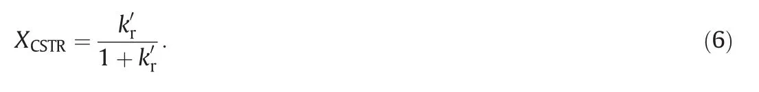
To study the relationship of overall ozone conversion and the Damköhler number,researchers usually chose two typical ideal reactor models:the plug- flow reactor(PFR)and the continuous stirred-tank reactor(CSTR)as the bases to evaluate the riser performance[32,45,47].Formulas for the conversion in PFR and CSTR can be derived as follows.
Plug flow reactor

Continuous stirred-tank reactor
As show n in Fig.12,it is noted that the overall conversion increases with increasing Damköhler number which is consistent with that of solid holdup as has been discussed in details in the above sections.

Fig.9.Ozone concentration in axial direction at extremely high density conditions[43].

Fig.10.Characteristics of flow structure at extremely high flux/density conditions[47].
Comparing the experimental overall conversion with the results calculated based on the two model reactors,it is obvious that the experimental conversion is not only less than that of PFR but also less than that of CSTR except w hen the Damköhler number is low.The results are similar to w hat had been reported by Ouyang et al.[45]in an LDCFB riser.The possible interpretation is that the reactor performance is related to the nature of the hydrodynamics in CFB system.There is a two-phase flow structure in CFB riser:a dilute phase of individually dispersed particles and/or small solid aggregates dominating in the center and a dense phase due to extensive particle aggregation becoming more significant toward the wall.In the wall region,the solid holdup is higher but with less reactant pass through this region compared to that in the center region.Thus,the reactants merely pass through the center of the bed,the “under-converted region”,and while less reactants pass though the w all region,“over-converted”region.This “gas bypassing”effect causes the reduction of the contact efficiency leading to lower overall conversion.Therefore,the experimental overall conversion in the riser is less than that of PFR or even less than that of CSTR[43].

Fig.11.Reactor performance in CFB riser at various operating conditions[43].

Fig.12.Reactor performance in CFB riser at various operating conditions.
4.4.Contact efficiency based on ozone reaction testing
To quantify the gas-solid contact using ozone decomposition reaction,Jiang et al.[32]proposed a concept of contact efficiency,α,representing the fraction of the external surface area of catalysts available for the diffused ozone reactant from the gas phase based on an ideal plug flow model reactor.For the first order reaction,the contact efficiency,α can be calculated as follow:

where εsis the cross-sectional average solid holdup.The lower value of α,the poor the reactor performance indicating that the CFB reactor deviates from an ideal plug flow reactor with negligible axial dispersion.
In order to determine “local”contact efficiency at different levels,it is assumed that the CFB riser consist of a series of plug- flow reactors.Based on this assumption,the riser was divided into ten compartments,bounded by the axial measurement points.In each compartment,particles are considered to be completely mixed and distributed uniformly.Considering a compartment with d z in height,a mathematical model based on the material balance for the reactant in the compartment can be developed:
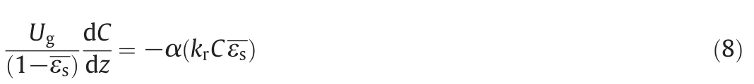
Thus,
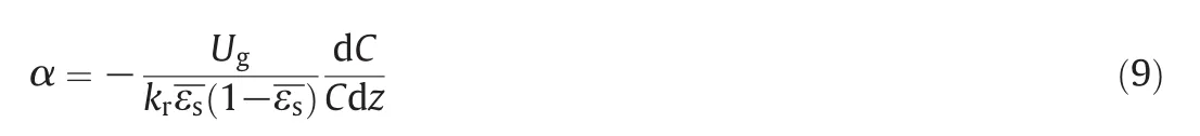
where εsis the cross-sectional average solid holdup and α is the contact efficiency at a height of z.The value of contact efficiency ranges from 0 to 1,with a larger value indicating more efficient gas-solid contacting and a better reactor performance nearly to the plug flow.
Fig.13 shows the axial distribution of“local”contact efficiency reported by Wang et al.[47].In general,the contact efficiency in the riser is below 1 and decreases from the reactor inlet towards the outlet as also reported by other researchers[31,41,42].Contact efficiency is much higher near the distributor probably due to the significant gas-solid turbulence and mixing in this region.Moreover,with increasing Ug(such as from 7 m·s-1to 9 m·s-1at constant Gs=600 kg·m-2·s-1)and/or decreasing Gs(such as from 600 kg·m-2·s-1to 100 kg·m-2·s-1at fixed Ug=9 m·s-1),the contact efficiency in the riser reactor increases.

Fig.13.Characteristics of flow structure at extremely high flux/density conditions[47].
This is not surprising since the particle distribution becomes more uniform with higher Ugand/or lower Gs,leading to a better gas solid contact.
Wang et al.[43]and other researchers[42]also investigated the relationship between contact efficiency and Damköhler number in the CFB reactors shown in Fig.14.It is seen that the overall contact efficiency decreases gradually with Damköhler number.Gas-solid contact efficiency obtained in this work is comparable to the results reported in the literature[41,42,45].Based on these data,an empirical correlation between overall contact efficiency and Damköhler number is derived as:


Fig.14.Characteristics of flow structure at extremely high flux/density conditions.
5.Future Research Needs
While many studies on contact efficiency have been carried out and much better understanding of CFB contact efficiency has been achieved recently,there are still many areas where further research is needed:
(1)As discussed,few studies have been conducted with high solid flux and high solid holdup in the circulating fluidized bed riser,more data and much detailed picture of both flow structure and the reactant distribution is needed to allow the development of the realistic and predictive reactor models of high density CFB reactors.
(2)Most studies did so far have employed FCC or sand particles.Systematic work with varying particle properties is needed to broaden know ledge of the contact efficiency of CFB reactors.
(3)Most data reported in the literature are from risers smaller than 100 mm in the diameter.More data from large scale units would be desirable.
(4)The available experimental data mostly reported the global hydrodynamic properties—such as averaged solid holdup and averaged particle velocity—with few measurements of microscopic properties such as the cluster size and solid holdup inside the clusters.The results are thus clouded by uncertainties about the actual contacting behavior between gas(reactant)and particles insides the CFB reactors.This field sorely needs experimental procedures capable of marking detailed measurements of cluster properties to relate the contacting performance to the cluster and other microscopic behavior.
6.Conclusion Remarks
Based on the papers review ed and discussed in this review,some conclusive remarks may be made as follows:
(1)Definition for gas-solid contact efficiency in a circulating fluidized bed based on indirect and direct measurement method have been presented,and the key results are introduced.
(2)Gas-solid contact efficiency is affected by operating conditions.Contact efficiency increases with increasing superficial gas velocity and/or decreasing solid circulation rate.
(3)Contact efficiency is also influenced by particle size distribution.Improved gas-solid contact as coarser particles(above a certain particle size limit)is used with coarser particles leading to more permeable clusters and(hence)greater surface efficiency.
(4)Solid holdup affects the overall ozone conversion with various trends in LDCFB and HDCFB riser.There is much more significant influence of solid holdup on overall reactant decomposition under higher superficial gas velocity and/or lower solid circulation rate.
(5)The values of calculated overall conversion are to some extent smaller than those obtained based on the two ideal model reactors(plug flow reactor and continuous stirred tank reactor)indicating that hydrodynamics affects the reactor performance in the CFB riser.The CFB riser is far away from an ideal plug flow reactor.
Nomenclature


Subscripts

[1]J.Yerushalmi,N.Cankurt,Further studies of the regimes of fluidization,Powder Technol.24(2)(1979)187-205.
[2]Y.Yerushalmi,A.A.Avidan,High velocity fluidization,in:J.F.Davidson,R.Clift,D.Harrison(Eds.),Fluidization,Academic Press,New York,1985.
[3]J.R.Grace,J.Baeyens,Gas fluidization technology,in:D.Geldart(Ed.),Gas Fluidization Technology,John Wiley&Sons Ltd 1986,pp.415-463.
[4]J.R.Grace,High-velocity fluidized bed reactors,Chem.Eng.Sci.45(8)(1990)1953-1966.
[5]K.Lim,J.Zhu,J.Grace,Hydrodynamics of gas-solid fluidization,Int.J.Multiphase Flow 21(1995)141-193.
[6]T.Shingles,A.F.McDonald,Commercial experience with Synthol CFB reactors,in:P.Basu,J.F.Large(Eds.),Circulating Fluidized Bed Technology II,Pergamon Press 1988,pp.43-50.
[7]J.X.Zhu,H.T.Bi,Distinctions between low density and high density circulating fluidized beds,Can.J.Chem.Eng.73(5)(1995)644-649.
[8]D.Van Zoonen,Measurements of Diffusional Phenomena and Velocity Pro filesin a Vertical Riser,Proceedings of Symposium on the Interaction between Fluids and Particles,Instn.Chem.Engrs.1962,pp.64-71(London).
[9]Y.Li,M.Kw auk,The dynamics of fast fluidization,Fluidization.,Springer,1980.537-544.
[10]D.-R.Bai,Y.Jin,Z.-Q.Yu,J.-X.Zhu,The axial distribution of the cross-sectionally averaged voidage in fast fluidized beds,Powder Technol.71(1)(1992)51-58.
[11]D.Bai,J.-X.Zhu,Y.Jin,Z.Yu,Internal recirculation flow structure in vertical up flow gas-solids suspensions Part I.A core-annulus model,Powder Technol.85(2)(1995)171-177.
[12]R.Dry,I.Christensen,C.White,Gas-solids contact efficiency in a high-velocity fluidised bed,Powder Technol.52(3)(1987)243-250.
[13]R.Dry,Radial particle size segregation in a fast fluidised bed,Powder Technol.52(1)(1987)7-16.
[14]H.Bi,J.Zhu,Static instability analysis of circulating fluidized beds and concept of high-density risers,AIChE J.39(8)(1993)1272-1280.
[15]A.S.Issangya,D.Bai,H.T.Bi,K.S.Lim,J.Zhu,J.R.Grace,Suspension densities in a highdensity circulating fluidized bed riser,Chem.Eng.Sci.54(1999)5451-5460.
[16]J.R.Grace,A.S.Issangya,D.Bai,H.Bi,J.Zhu,Situating the high-density circulating fluidized bed,AIChE J.45(10)(1999)2108-2116.
[17]A.S.Issangya,J.R.Grace,D.Bai,J.Zhu,Further measurements of flow dynamics in a high-density circulating fluidized bed riser,Powder Technol.111(1)(2000)104-113.
[18]J.Liu,J.R.Grace,X.Bi,Novel multifunctional optical- fiber probe:II.High-density CFB measurements,AIChE J.49(6)(2003)1421-1432.
[19]F.Wei,X.Wan,Y.Hu,Z.Wang,Y.Yang,Y.Jin,A pilot plant study and 2-D dispersion-reactor model for a high-density riser reactor,Chem.Eng.Sci.56(2)(2001)613-620.
[20]F.Wei,H.Lin,Y.Cheng,Z.Wang,Y.Jin,Pro files of particle velocity and solids fraction in a high-density riser,Powder Technol.100(2)(1998)183-189.
[21]J.R.Grace,Re flectionson turbulent fluidization and dense suspension up flow,Powder Technol.113(3)(2000)242-248.
[22]J.Pärssinen,J.-X.Zhu,Particle velocity and flow development in a long and high- flux circulating fluidized bed riser,Chem.Eng.Sci.56(18)(2001)5295-5303.
[23]J.Pärssinen,J.X.Zhu,Axial and radial solids distribution in a long and high- flux CFB riser,AIChE J.47(10)(2001)2197-2205.
[24]M.A.Van Der Hoef,M.Van Sint Annaland,J.A.M.Kuipers,Computational fluid dynamics for dense gas-solid fluidized beds:A multi-scale modeling strategy,Paper presented at IACRE182004,2005.
[25]A.Yan,J.Zhu,Scale-up effect of riser reactors(1):axial and radial solids concentration distribution and flow development,Ind.Eng.Chem.Res.43(18)(2004)5810-5819.
[26]C.Wang,J.Zhu,S.Barghi,C.Li,Axial and radial development of solids holdup in a high flux/density gas-solids circulating fluidized bed,Chem.Eng.Sci.108(2014)233-243.
[27]J.Z.Liu,J.G.Grace,H.T.Bi,H.Morikawa,J.Z.Zhu,Gas dispersion in fast fluidization and dense suspension up flow,Chem.Eng.Sci.54(22)(1999)5441-5450.
[28]H.Y.Zhu,J.Zhu,Comparative study of flow structures in a circulating-turbulent fluidized bed,Chem.Eng.Sci.63(11)(1999)2920-2927.
[29]X.Qi,H.Zhu,J.Zhu,Demarcation of a new circulating turbulent fluidization regime,AIChE J.55(3)(2009)594-611.
[30]C.Fryer,O.E.Potter,Experimental investigation of models for fluidized bed catalytic reactors,AIChE J.22(1)(1976)38-47.
[31]J.Grace,G.Sun,In fluence of particle size distribution on the performance of fluidized bed reactors,Can.J.Chem.Eng.69(5)(1991)1126-1134.
[32]P.Jiang,H.Bi,R.H.Jean,L.S.Fan,Baffle effects on performance of catalytic circulating fluidized bed reactor,AIChE J.37(9)(1991)1392-1400.
[33]H.Bi,P.Jiang,R.-H.Jean,L.S.Fan,Coarse-particle effects in a multisolid circulating fluidized bed for catalytic reactions,Chem.Eng.Sci.47(12)(1992)3113-3124.
[34]R.Dry,C.White,Gas-solid contact in a circulating fluidized bed:the effect of particle size,Pow der Technol.70(3)(1992)277-284.
[35]S.Pagliolico,M.Tiprigan,G.Rovero,A.Gianetto,Pseudo-homogeneous approach to CFB reactor design,Chem.Eng.Sci.47(9)(1992)2269-2274.
[36]S.Ouyang,J.Lin,O.Potter,Ozone decomposition in a 0.254 m diameter circulating fluidized bed reactor,Powder Technol.74(1)(1993)73-78.
[37]H.Schoenfelder,M.Kruse,J.Werther,Two-dimensional model for circulating fluidized-bed reactors,AIChE J.42(7)(1996)1875-1888.
[38]J.-X.Zhu,Y.Ma,H.Zhang,Gas-solids contact efficiency in the entrance region of a co-current down flow fluidized bed(downer),Chem.Eng.Res.Des.77(2)(1999)151-158.
[39]O.Bolland,R.Nicolai,Describing mass transfer in circulating fluidized beds by ozone decomposition,Chem.Eng.Commun.187(1)(2001)1-21.
[40]C.Fan,Y.Zhang,X.Bi,W.Song,W.Lin,L.Luo,Evaluation of downer reactor performance by catalytic ozone decomposition,Chem.Eng.J.140(1)(2008)539-554.
[41]D.Li,J.Zhu,M.B.Ray,A.K.Ray,Catalyticreaction in a circulating fluidized bed downer:ozone decomposition,Chem.Eng.Sci.66(20)(2011)4615-4623.
[42]D.Li,A.K.Ray,M.B.Ray,J.Zhu,Catalytic reaction in a circulating fluidized bed riser:ozone decomposition,Powder Technol.242(2013)65-73.
[43]C.Wang,G.Wang,C.Li,S.Barghi,J.Zhu,Catalytic ozone de composition in ahigh density circulating fluidized bed riser,Ind.Eng.Chem.Res.53(16)(2014)6613-6623.
[44]C.Wang,S.Barghi,J.Zhu,Hydrodynamics and reactor performance evaluation of a high flux gas-solids circulating fluidized bed downer:Experimental study,AIChE J.60(10)(2014)3412-3423.
[45]S.Ouyang,X.G.Li,O.Potter,Circulating fluidized bed as a catalytic reactor:experimental study,AIChE J.41(6)(1995)1534-1542.
[46]P.Jiang,R.H.Jean,H.T.Bi,L.S.Fan,Ozone decomposition in a catalytic circulating fluidized bed reactor,in:P.Basu,M.H.,M.Hasatani(Eds.),Circulating Fluidized Bed Technology III,Pergamon Press 1990,pp.557-562.
[47]C.Wang,J.Zhu,S.Barghi,Performance evaluation of high density riser and downer:Experimental study using ozone decomposition,Chem.Eng.J.262(2015)478-489.
[48]A.Yan,W.Huang,J.J.Zhu,The influence of distributor structure on the solids distribution and flow development in circulating fluidized bed s,Can.J.Chem.Eng.86(6)(2008)1023-1031.
[49]H.Zhu,J.Zhu,Gas-solids flow structures in a novel circulating-turbulent fluidized bed,AIChE J.54(5)(2008)1213-1223.
杂志排行

Chinese Journal of Chemical Engineering的其它文章
- Scoping biology-inspired chemical engineering☆
- Review on the nanoparticle fluidization science and technology☆
- Multi-functional forward osmosis draw solutes for seawater desalination☆
- Bio-inspired enantioseparation for chiral compounds☆
- Process engineering in electrochemical energy devices innovation☆
- In-situ design and construction of lithium-ion battery electrodeson metal substrates with enhanced performances:A brief review☆