Overview on the Development of Autonomous Underwater Vehicles(AUVs)
2016-05-16,
,
(1.Shipbuilding Engineering Department,Military Technical College,Cairo,Egypt;2.College of Shipbuilding Engineering,Harbin Engineering University,Harbin 150001,China)
Overview on the Development of Autonomous Underwater Vehicles(AUVs)
ALAAELDEEN M.E.Ahmed1,DUAN Wen-yang2
(1.Shipbuilding Engineering Department,Military Technical College,Cairo,Egypt;2.College of Shipbuilding Engineering,Harbin Engineering University,Harbin 150001,China)
Autonomous underwater vehicles(AUVs)became an interesting research area because of their emerging applications in oceanographic survey.The wave glider is a surface unmanned vehicle (SUV)which uses the power of the ocean to propel itself:a technological leap from typical AUVs powered by motors and buoys with expensive mooring systems.In this paper,the most effective types of AUVs is discussed.The history of the development of each type is presented first and the technical aspects are also discussed.And the wave glider as a new type of underwater robotics used in marine sector will be briefly discussed to give a complete overview of the past,present and future of the AUVs development.The purpose of studying wave glider is to discuss the efficiency and functionality of it to replace many AUVs for a variety of applications.The results of study demonstrate that the wave glider is applicable in many fields of applications.Wave glider offers a cheaper,more economical and environmentally sound method of monitoring the seas compared to other AUVs and also has no need for ship time,mooring lines and at-sea servicing.
autonomous underwater vehicle(AUVs);underwater gliders;wave glider
0 Introduction
Oceans cover over 71%of the planet’s surface but the majority of the ocean is yet to be explored through traversing the oceans to record data to keep track of meteorological and oceanographic phenomenon.A new way to explore the oceans is needed.With improvements to the current exploratory systems,a safer and more efficient method can be achieved.However, new technology is being designed to explore the dark seas and unmanned vehicles have been successful by using computers and technological advancements.
Autonomous Underwater Vehicles(AUVs)are remarkable machines that revolutionized the process of gathering ocean data.Their major breakthroughs resulted from successful developments of complementary technologies to overcome the challenges associated with autonomous operation in harsh environments.During the last decades,AUVs have gone through remarkable developments.In the late eighties and early nineties,the first prototypes required an extraordinary effort and ingenious engineering solutions to compensate for the technological limi-tations in terms of computational power,batteries,and navigation sensors.The initial developments continued steadily and by the end of the last century,AUVs have gradually moved from the controlled academic environment into challenging operational scenarios,covering scientific,commercial and military applications.
Most of the advances in AUV capabilities aimed at reaching new application scenarios and decreasing the cost of ocean data collection,by reducing ship time and automating the process of data gathering with accurate geo location.The design of AUVs is governed by a complex tradeoff between the critical requirements of the planned missions and the main constraints on fabrication,assembly and operational logistics.The current pursuit of efficiency has pushed the concept of specific vehicles for specific tasks,frequently to take advantage of modular designs to accelerate the assembly time(Caccia et al,2000)[1].
Underwater robotics is a peculiar field of knowledge,bringing together specific complementary knowledge in mechanical,electrical engineering and in computer science.In the last decade,with the improvements in computational power,battery technology and miniaturization of electronic systems,AUVs had become less cumbersome and more applicable to be used as test beds for new techniques for data processing.The access to operational vehicles was further facilitated and more prototypes became accessible for testing new algorithms and solutions as smaller,lighter and less expensive equipments have become available(Correia et al,1991)[2].
The wave glider is a surface vehicle with an attached sub-surface wing system.The wing system is composed of six individual wings that adjust to the current,speed and direction of passing waves.This system propels the surface component forward,negating the need for a motor.Wave glider can be programmed to travel or to keep station at a certain location which is helpful in the need for replacement of buoys with expensive mooring systems.Wave glider has instruments on the surface component that can be customized for Acoustic Doppler Current Profiler(ADCP)and Conductivity,Temperature and Depth of the Ocean(CTD)measurements,passive monitoring of marine life and other commercial and defense applications.The instruments are powered by solar panels on the surface component,making the wave glider a self-sustaining vehicle which transmits data to land in real-time sequence,allowing for accurate and easy monitoring of the vehicle’s trip and the data collected(Hine et al,2007)[3].In this paper,background history of AUVs is provided in Chapter 1,technology of AUVs is discussed in Chapter 2,Chapter 3 describes the unlimited energy autonomy,the technology of underwater gliders is presented in Chapter 4,while Chapter 5 provides overview for wave glider and finally Chapter 6 presents the conclusion.
1 AUVs historical background
Gathering data from the seas had been a focus since 1872.The HMS Challenger by Captain George Nares set out between 1872 and 1876 to gather information on ocean temperature, currents,marine life and seafloor geology.The Challenger’s first voyage set off from Englandand traveled through the Atlantic Ocean around the ape of Good Hope.It traveled though the Antarctic Circle,Indian Ocean,and the Pacific visiting New Zealand,Australia,and the Hawaiian Islands before returning back to England in 1876 as shown in Fig.1.

Fig.1 Challenger expedition(The route of HMS Challenger,2015)
The Challenger discovered the Marianas Trench and the Mid-Atlantic Ridge.It also revealed the first outline of the Atlantic Ocean.From data provided by the Challenger,scientists were able to map some of the currents and temperature distributions.The discoveries of the Challenger paved the way for studying the oceans and led many other countries to take interest and start other expeditions.Mathew Fontaine Maury,an American scientist,studied thousands of ships’logs and charts.He published the wind and current chart of the North Atlantic.From this data,charts of the ocean currents and wind patterns allowed captains to plan the best routes for travel.
In the late 1800s into the 1900s,Prince Albert of Monaco used a similar method to figure out what happened to the Gulf Stream as it approached Europe.He determined that the Gulf Stream splits in the northeastern Atlantic.One branch heads toward Ireland and Great Britain,while another part of the Gulf Stream heads south past Spain and Africa,and then back west(Dive and Discover,2005)[4].
Technology has led to a new era in ocean exploration in which no need for ships.Long term observation can be taken using many sensors and instruments to make continuous measurements of many ocean properties.The data can then be transmitted to scientists through underwater cables linked to moored buoys and transmitted to satellites in real time.The three most common methods of getting data are remotely operated vehicles(ROVs),AUVs and buoys. The use of these instruments has greatly increased the reach of oceanographers in the line of research and knowledge of the oceans.
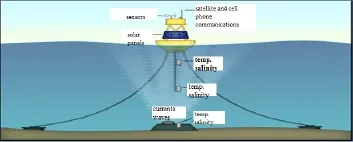
Fig.2 Data buoy(Data buoy types,2015)
One of the most common systems for obtaining data is the buoys as shown in Fig.2. They measure and transmit data automatically and transmit them in real time through different systems.The observations from buoys have led to significant advances in modeling and understanding global weather and climate systems on every space and time scale.Buoys are one of the most cost effective means for obtaining meteorological and oceanographic data.Two types of buoys exist,depending on the needed application,Drifting and moored data buoys can be used(Data Buoy Types,2015)[5].
There are many different types of them depending on the applications and measurements needed in different areas of the ocean.They have been used since the 1970s and are stillbeing used until now.Lagrangian drifter is a type of drifting buoys which measures the velocity of currents at the depth of its drogue while also collecting surface and other subsurface measurements.
Moored buoys are normally relatively large,stationary and expensive platforms.They can vary from a few meters in height and breadth,to over 12 meters.Measurements from the mooring include surface variables(wind,air and sea surface temperature,salinity,air pressure),as well as subsurface temperatures down to a depth of 500 plus meters,and also serving maritime safety needs.The buoys are very difficult to deploy due to their size and they also require a robust mooring system to keep them from setting adrift during times of large waves and stormy conditions.
The AUV definition comes from the oil and gas industry.The oil industry developed the first conceivable untethered underwater vehicle which was a self-propelled torpedo in 1868. The more traditional history began in 1960 with Dimitri Rebikoff’s Sea Spook.The next AUVs created were the Applied Physics Laboratory’s Self Propelled Underwater Research Vehicles developed in 1963 and 1973,followed by the Unmanned Arctic Research Submersible (UARS)in 1972.After 1973 AUV developments were slow until the late 1980s when significant advances in energy,computing,and navigation were developed(Bellingham,1994)[6].

Fig.3 AUV on mission(www.nauticalcharts. noaa.gov/csdl/AUV.)
AUVs are programmable robotic vehicles that drift,cruise or glide through the ocean.The AUVs can be programmed to go anywhere and record data throughout the entire journey or only at certain points.Some AUVs can make their own decisions based on the data received and interpreted along the way.They are very simple to deploy and easy to control from a ship or land-based control center.AUVs communicate periodically through underwater beacons or real-time via satellite as shown in Fig.3, (AUV lab.MIT Sea grant,2012)[7].The main reason for using AUVs is that they are the most effective way to obtain a large series of data.As result of their low cost and high level of safety,AUVs usually offer the best or only option for many missions.They are the newest technology for obtaining data and much advancement is still underway.
AUVs have not been proven to be cost effective at deep depths.Three AUVs have gone to depth more than 6 000 meters,including the Naval Ocean Systems Center’s Underwater Search System(AUSS),the French vehicle EPAULARD, and the Soviet Union’s MT-88.The deep water AUV systems proved to be too expensive regarding equipment and operational costs due to the complexity and size required to reach those depth.A large portion of research and development in the United States has been formilitary purposes as shown in Fig.4.Vehicles weighing an excess of 6 metric tons have been built.They cost millions of dollars and require large support vessels and have limited handling capabilities.
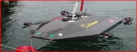
Fig.4 Military AUV(www.marineinsight. com/marine/AUV)
Small AUVs were previously thought of as impractical because they did not have the capacity,durability or range that was required.In recent years,the scientific community has seen a need for small,high performance,low cost AUVs.The lower cost of the AUVs allows scientists to deploy greater numbers of them.This results in a larger number of data points being collected for analysis.They also allow more dangerous missions to be attempted without the fear of losing extremely expensive pieces of equipment.
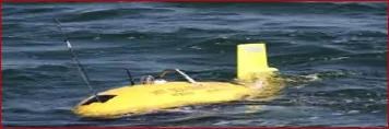
Fig.5 MIT’s Odyssey(Odyssey IV Robot,2008)
In 1991 and 1992,MIT Sea Grant College Program’s AUV Laboratory constructed a vehicle called the Odyssey;it underwent trials in the Atlantic Ocean off of New England before being deployed from the Nathaniel B. Palmer off of Antarctica in early 1993.The success of this program,led to the creation of a second generation of the Odyssey:The Odyssey IV weighs 1000 lbs.and is 6.5 ft.long,it has twin side-mounted thrusters that can propel up to 3 knots which also proved to be very successful in autonomously taking measurements up to 1 400 meters under Arctic sea-ice as shown in Fig.5.In 1997 the Sea Grant College Program’s AUV lab primarily focused on developing an autonomous ocean sampling network that would collaborate the data collected by many AUVs over many trials(Odyssey IV Robot,2008)[8].
Bluefin Robotics was developed in 1997 and opened a manufacturing facility in 1999. The commercial industry soared with the growth of Bluefin Robotics.The transition led to an increase in AUVs technology and yielded a mobile network for ocean observation.AUVs are usually shaped similar to a torpedo.They can be driven by buoys,a battery or a motor with a propeller,wave energy driven or solar driven in conjunction with batteries and a propeller.

Fig.6 Wave Glider(www.bing.com/images/ wave glider)
Liquid Robotics has developed a completely autonomous vehicle that draws all of its power from the sun and the sea as shown in Fig.6.The propulsion works primarily off of the buoyancy of a surface float that pulls the wings upward and the negative buoyancy of the wings causing them to sink.The up and down motion of the wing system through the water and the wings’freely pitching cause the wings to excel forward,pulling the float by its 7 meter tether,therefore there is no need to be fueled.The electrical system on board is powered by solar panels on the floating surface component which power the remote control and onboard instruments that allow the wave glider to constantly monitor and test different aspects of the ocean.
The first wave glider was delivered in 2008.In 2011,NOAA’s NDBC deployed the firstoperational wave gliders to monitor real time observations throughout the Gulf of Mexico. They also released a second wave glider to record tsunami observations and data,also helped the NDBC enhance coastline inundation,maritime safety,oceanographic and meteorological observations(Liquid Robotics,2011)[9].Liquid Robotics has proved the success of the wave glider with a 60 000-kilometer journey called PACX.Four wave gliders traveled from San Francisco to Hawaii and then broke into two pairs.One pair proceeded to Australia while the other traveled to Japan(The Wave Glider Technology,2012)[10].
2 AUVs evolution
Remotely Operated Vehicles(ROVs)essentially reached technological maturity in the‘80s(Christ et al,2011)[11].These vehicles are characterized by an open-frame structure,and by the umbilical cable through which data and commands are exchanged.Often energy is supplied to the vehicle from the surface commanding platform.Due to its non-slender body structure and the maximum tether length,ROVs have limited movement capabilities,designed first of all to exert power.They are mainly used for underwater work in the offshore industry.In particular,there is a trend toward replacing human divers whenever possible with ROV deployment,in scientific environmental monitoring,civil and military inspection,archaeological work(Conte et al,2009)[12];this has led to the commercialization of a great number of small, lightweight vehicles,deployable even from rubber boats.
Unlike for ROVs,in the early‘90s,there was no commercially available AUV.The difficulties linked to the absence of any kind of communication between the vehicle and a mission monitoring station had so far prevented the development of vehicles with these characteristics. Although Pool tests are important,they are not representative of the behavior at sea;and the risks associated to experimentation at sea preventing most of the research labs with low budget(typically,university labs)to invest in this particular field.
In the USA,Draper Labs developed two large-scale,torpedo shaped vehicles as test-bed for Navy projects(Blidberg,2001)[13].In parallel to the ambitious military-oriented programs, there were research groups focusing on the development of smaller vehicles for inspection and mapping purposes.The MIT group in the USA developed the Odissey AUV(Bellingham et al, 2005)[14],while in Europe,the European Union sponsored the project that led to the MARIUS AUV(Pascoal et al,1997)[15],which was one of the first vehicles not shaped as a torpedo.A vision for the future of operational oceanography,exploiting the new possibilities of autonomous sensing,including AUVs,was put forward in Curtin et al(1993)[16],a famous paper in which the concept of Autonomous Ocean Sampling Network(AOSN)was formulated:it was envisioned that future oceanographic measurements would take place through a combination of fixed and mobile autonomous sensors,all connected in a network,some installed permanently,and some deployed on demand,according to the evolution of the oceanic features of interest Yuh et al (1994)[17].

Fig.7 HUGIN AUV on deck before deployment (Hagen et al,1999)
The second half of the‘90s saw several initiatives addressed the critical technologies there outlined.In particular,Kongsberg Maritime,together with the Norwegian Defense Research Establishment(FFI)and the national oil company Statoil,and with additional support by university labs,developed the HUGIN class AUV as shown in Fig.7(Hagen et al, 1999)[18].This vehicle was specifically designed for seabed and sub-bottom mapping surveys in deep water,with endurance originally up to two days.The success of the project was due to the capability developed in-house to have an acoustic communication link with the vehicle through the Hi-Pap localization and acoustic modem system.This system allowed to monitor the mission from a surface ship,and provided georeferentiation to the vehicle.The Hugin 3000 completed its acceptance and qualification tests in 2000.
By 2007,the commercial HUGIN fleet had completed 150.000 km of seabed surveys,first acquired by C&C Technologies and deployed in the Gulf of Mexico.The reliability of the system made it an immediate success and gave momentum to the AUV development,despite its costs and the need of a surface platform to follow it during operation.One particular aspect, was the demonstration that the operational costs of a HUGIN survey were lower than the equivalent costs of the same survey with a deep-tow system;moreover,data quality from the HUGIN AUV was better(Chance et al,2000)[19].The success of the initiative led to the development of a defense version of it and to another version for exploration of deeper sites.
In the same period(Marco et al,2001)[20],the MIT group launched a long-term experimentation program together with the NATO Undersea Research Centre(NURC)in Italy.The GOATS program allowed a series of tests with the new-generation Odyssey vehicles employed as platforms for acoustic and oceanographic sensors.One of the clever aspects was its openness to participation of research group from all over the NATO countries,with NURC making available its sea-going facilities and experience(Bovio et al,2001)[21].
The third key initiative of the second half of the‘90s was the development of the REMUS AUV at the Woods Hole Oceanographic Institute(WHOI)(Allen et al,1997)[22].The REMUS is a very small,lightweight vehicle,specifically designed for coastal oceanography,easy to carry and deploy,and with costs less than the HUGIN.Clearly,the fields of application of the REMUS was complementary to that of the HUGIN;it led to reduce the budget cost of the research,development and technology transfer,while reaching the mission goal.REMUS vehicles were deployed in operational missions by the US Navy in 2003(Stokey et al,2001)[23].
The HUGIN and REMUS projects,as well as the GOATS program,were instrumental in gaining visibility and appreciation from the user’s community,and at the end of the‘90s the degree of confidence in the potentiality of AUVs was high both in the scientific and the user community.In the same period,there were research initiatives in Japan(Ura,2000)[24].Theemphasis of Ura’s group focused on on-board intelligence and mission adaptation capabilities of the systems,and resulted in a series of different vehicles,starting from the mid-‘90 s,which were able to conduct missions in a great variety of situations.
Autonomy and on-board intelligence were present in all the vehicles developed in the late‘90s,and many vehicles proved to be capable of conducting missions without need of acoustic monitoring,supervision and external localization aid.However,for most of the mapping survey missions,acoustic localization with external sensors had to be present,to be used at least in a post processing phase to properly georeference the data,due to the drift of onboard Inertial Measurement Units(IMU)(Caiti et al,2005)[25].
Among these new applications;Autonomous Surface Crafts(ASC)started to gain momentum(Leonessa et al,2003;Alves et al,2006)[26-27].ASCs are easier to develop than AUVs from the point of view of the navigation,having access,at least in principle,to GPS.Experimentation with ASCs makes it possible to decouple navigation difficulties from all the other sources of disturbances peculiar to the marine environment.So,it may have been expected to see ASCs as predecessors of AUVs.The progress in the two fields had proceeded at best in parallel. However,ASCs have now a clear potential for applications in defense and security and for hazardous inspection missions(Mies G,2010;Bash J F,2008)[28-29].From a scientific viewpoint, ASCs are an ideal vehicle to collect samples from the sea surface,for oceanographic and marine biology purposes.They can also be used as test-bed for multi-vehicle operations.
Another class of vehicle is oceanographic gliders as in Fig.8.These vehicles were designed primarily for oceanographic purposes,with the mission of sampling in depth of the water column when moving from one station to another.Usually equipped with standard CTD probes,gliders do not have propellers,but change their buoyancy and asset by active ballast variation and displacement;once the system is negative and positive buoyant and it has the appropriate pitch;the vehicle control surface will produce a net movement in the horizontal plane.So gliders are characterized by a typical yo-yo motion in the water column while moving from one point to another.Therefore actuation of the system is required only to change buoyancy and pitch.Indeed,gliders have shown the ability of conducting ocean sampling mission for several months(Holling et al,2010)[30].Each time the vehicle resurfaces;it gets into GPS and satellite contact,transmits the data to a ground station,and receives further indication on the next route to pursue.Because the path following accuracy and speed are not to be expected from gliders,they have been very versatile regarding mission reconfiguration and adaptation,and in coordinated missions(Bellingham,2009;Leonard et al,2010)[31-32].
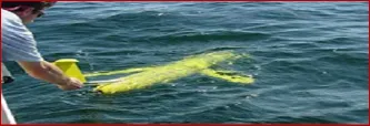
Fig.8 Slocum glider(www.webresearch.com)
3 Unlimited energy autonomy
As the fleet of AUVs increases,and long-term missions are considered,the energy effi-ciency of the vehicles becomes a key issue.So far progress in endurance has been linked to progress in electrical batteries;new generation batteries(Hyakudome et al,2011)[33],allow for more energy storage while at the same time reducing size and weight.This allows an increase in mission time even for small lightweight vehicles.However,this is not yet enough to guarantee mission times of more than few days at the very best.Moreover,the increase in functionalities carried out increase the energy requirements.Acoustic modems do not come cheaply,in terms of energy budget;some payloads are also energy-consuming devices.
Other energy saving systems had been explored.The group led by Blidberg had pioneered the investigation on solar-powered AUVs(Blidberg et al,2005)[34];with solar panels accumulating energy when the vehicle is at the surface.The very recent wave-glider vehicle is a surface autonomous vehicle that exploits wave motion to produce a net horizontal movement in the desired direction(Frolov et al,2011)[35].The system is complemented with solar panels,and it has the potential of being a movable surface sampling station with unlimited energy autonomy;it already has been applied in environmental and oceanographic application,and it is an example of a specialized vehicle entirely supported by green energy.In March 2012,four months after the start,a group of wave gliders arrived from San Francisco to Hawaii,having travelled 2500 miles across the Pacific Ocean.
Nature-inspired design may lead to improve efficiency and reduce consumption.Examples of design criteria and specific realizations are in Yamamoto(2006)[36], as shown in Fig.9.Another instance of design aimed at exploiting biomimetic features is the Octopus project,sponsored by the European Union,in which the functionalities of octopus tentacles and propulsion are replicated to obtain a floating vehicle with manipulation capabilities(Laschi et al,2009)[37].
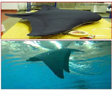
Fig.9 A flat-fish robot(Yamamoto,2006)
4 Underwater gliders development
There are currently over 50 different types of AUVs in research and commercial operation.A few of these vehicles are 100 percent powered.Three of these vehicles are from the U-nited States of America,torpedo shaped,have the ability to do studies in glide mode and move without power as shown in Fig.10.These are the Slocum glider,Spray and Seaglider currently sold by Bluefin Robotics Corporation.
These vehicles glide slowly down to a specified depth and then back to the surface using a buoyancy control system tracing a saw-tooth profile,observing data such as standard CTD.When the vehicle is at the surface,positioning is obtained via GPS and communication between the vehicle and the home base via satellite.The three gliders are small semitorpedo shaped AUVs that control their forward motion by the glide path taken and changing buoyancy.Wings allow steerable gliding,thus horizontal propulsion.
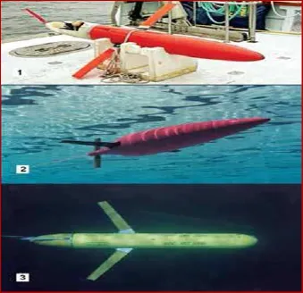
Fig.10(1)Spray;(2)Seaglider;(3)Slocum Glider (www.bing.com/images/search/Slocum+Glider)
These vehicles are excellent at the tasks which they are designed to do(i.e., very long term,very little power,slow cruising of the ocean’s water column),but they are limited as to the type of payloads they can carry,and they have no active propulsion for times that require more than buoyancy thrust.These autonomous underwater gliders each change their buoyancy to be able to travel horizontally in the ocean’s water column using the lift on their wings,like a normal glider does to convert vertical velocity into forward motion.They were designed specifically for long term sampling and easy deployment and recovery by a minimal crew on any size boat or ship.These vehicles are relatively inexpensive,typically less than the cheapest powered AUV’s, costing less than a week and a half of ship time for a research vessel.
4.1 Spray,Slocum battery and Slocum thermal gliders
The Slocum Battery and Spray Gliders have been optimized for missions in shallow coastal environments(Webb et al,2001;Sherman et al,2001)[38-39].Each of these vehicles uses battery power to control the buoyancy.The Slocum battery is controlled by different methods.The pitch and roll are controlled by translating and rotating the internal battery packs.A rudder controls the turning rate and the pitch moment and the buoyancy at the surface are aided by the inflation of an airbladder.The Slocum battery uses a shallow water single stroke pump to move water in and out of the vehicle for volume control.The communication and GPS antennas are embedded in a vertical stabilizer,which rises above the ocean surface when the vehicle is pitched; forward(Griffiths,2002)[40].
The spray glider as shown in Fig.11 is similar to the Slocum battery glider but with a more hydrodynamic shape giving it about 50%less drag than the Slocum battery.The spray was targeted for long-range up to 4 700 km and down to 1 500 meters depth by optimizing the use of energy.Use of a high-pressure reciprocating pump with external bladders makes the vehicle similar to the ALACE floats(Davis et al,1992)[41].

Fig.11 Spray’s method of travel (Davis et al,1992)
The glide control in Spray is achieved exclusively by axial translation and rotation of internal battery packs.Pitch is controlled simply by moving the center of gravity in the manner of a hang glider.Turning is initiated by rolling.This gives the lift vector a horizontal component and induces vehicle sideslip in the plane of the wing in the direction of the buoyant force(APL,2008)[42].
The Slocum thermal glider was developed and optimized for long duration missions with a well-developed thermo cline.The propulsion of the vehicle is derived from harnessing the energy of the thermal gradient between the ocean’s surface and bottom for use as the vehicle’s propulsion.In missions with electric-powered gliders,60%-85%of the energy consumed goes into propulsion,so a thermal-powered glider may have a range 3-4 times that of a similar electric-powered vehicle.Slocum thermal is nearly identical to Slocum battery except for its thermal buoyancy system and using roll rather than a movable rudder to control turning. The specifications of the Spray,Slocum(Battery&Thermal)gliders are shown in Tab.1.

Tab.1 Comparison between Spray,Slocum battery and Slocum thermal gliders specifications(Wood Stephen,2008)
4.2 Seaglider&Deepglider
The Seaglider and Deepglider as shown in Figs.12 and 13 are similar to the Spray and Slocum battery gliders.They are identical in looks but the Deepglider is made out of a composite pressure hull of thermoset resin and carbon fiber making it capable of diving to a depth of 6 000 meters(Osse&Lee,2007)[43].The Seaglider using an efficient use of energy allows it to operate one-year 4 600 km missions(Eriksen et al,2001)[44].
Seaglider uses a hydrodynamic aluminum pressure hull that is contained within a freeflooded fiberglass fairing that supports the wings.The flooded aft section is used to carry selfcontained instruments on the both vehicles.They have a trailing antenna rod and the fairingencloses the pressure hull.In weak currents,the vehicles can maintain position by pitching vertically with minimal buoyancy.As with the Slocum series and Spray gliders,the Seaglider and Deepglider control their buoyancy with a hydraulic system similar to the ALACE system. In both gliders,it is the movements of internal masses which control the pitch and yaw of the vehicle while gliding,and also raise the antenna for communication and GPS navigation.The Seaglider has made thousands of dives since its inception in 1999(Osse et al,2007)[45].The first Deepglider tests were made in November 2006 off the Washington state coast where it made test dives for 39 days with dives down to 2 713 meters depth and a lateral distance of 220 km.The specifications of the both vehicles are shown in Tab.2.
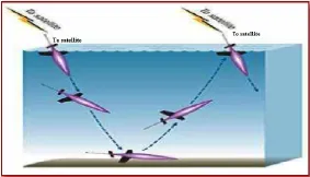
Fig.12 Seaglider’s method of travel (Eriksen et al,2001)

Fig.13 Deepglider(Osse et al,2007)
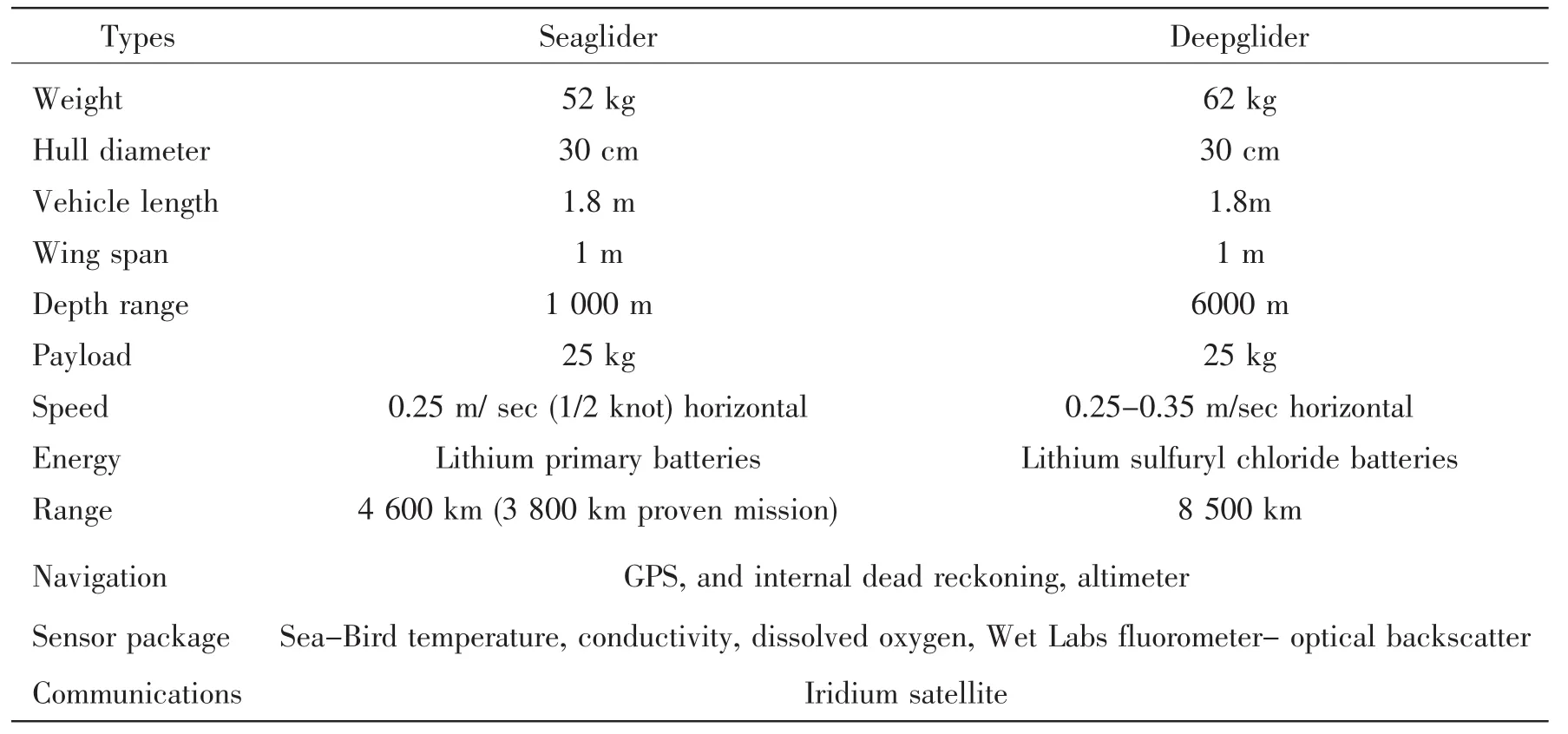
Tab.2 Comparison between Seaglider and Deepglider specifications(Osse et al,2007)[45]
The Spray,Slocum(Battery&Thermal),Seaglider and Deepglider are very similar in size and general characteristics.They were designed with the same objectives,specifically in being small and easily deployed and recovered by only a couple of people.The vehicles are dependent on the energy efficiency and glide trajectory angle during each traverse to monitor the ocean.Currently,various institutions are starting the investigation of long duration,highly efficient,slow-speed,powered autonomous underwater vehicles.These investigations will lead to the development of new highly optimized efficient wings.
4.3 ALBAC and Hybrid AUV-Powered gliders
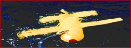
Fig.14 ALBAC glider(Kawaguchi et al,1993)
The ALBAC is one of the first gliders which conducted sea trials at the Suruga Bay of Japan in 1992.The vehicle does not have an active buoyancy control system,but a simple drop weight system with only one glide cycle. The ALBAC as shown in Fig.14 has fixed wings and vertical and horizontal tail.It is 1. 40 m long,1.20 m in wide,weighs 45 kg,and can dive to depths of 300 m at speeds of one to two knots.It has horizontal tail fins which change angle at inflection from downwards to upwards gliding,a feature not present in other gliders.The wings and tail are larger in comparison to the body than on Slocum,Spray or Seaglider.ALBAC moves a battery pack internally to control pitch and yaw in the same manner as Seaglider.Because it has no ballast pump,ALBAC carries batteries to power its instruments and actuators.
ALBAC carries flight sensors including compass,depth,pitch,roll,and a propeller-type velocity meter.Slocum,Spray and Seaglider do not carry velocity meters in order to conserve power and because of the difficulty of accurately sensing velocity at glider operating speeds (Graver,2005)[46].The vehicle has no external communication ability.It has a 3-liter dry payload space for scientific measurement devices.It consists of a 1/2 ellipse shaped front cap,a cylindrical pressure hull,a corn shape tail cap with a vertical stabilizing fin,a pair of wings, tail wings and various electronic devices(Kawaguchi et al,1993)[47].
Another glider under development is a hybrid,which is designed to travel under power, glide mode or both.This vehicle is being designed to obtain water samples,make photographic or video images of specimens in the water column and specify the environmental characteristics of the data field.Also,it is expected to possess a wide array of traditional oceanographic instruments that can be used by the vehicle’s control system to make mission and navigational changes.The vehicle’s ability to obtain water samples and photographs directly affects the design of the vehicle more than the addition of oceanographic instruments.
The AUV powered glider was designed for mission applications to 6 000-meter ocean depths.It has modular design to ship easily in small boxes and to have interchangeable scientific modules,quick assembly&disassembly of AUV components,easy battery access for replacement and recharging during missions,reasonable space for scientific&instrument payload and capable of landing.
Unlike torpedo shaped survey AUVs,the structure of the AUV-powered glider has a rectangular frame that is approximately 1.5 by 2-meters square.The version shown in Fig.15 is for marine biologists,biological oceanographers and other scientists needing samples and photographs of organisms in the water column. The main vehicle specifications for the AUV are 293 kg dry weight(without instruments and drop weight system),1.93 m length,1.59 mwidth at flares 1.69 m,0.58 m housing depth.The glider is equipped with two 12-volt longitudinal and two 12-volt DC brushless vertical thrusters mounted on the forward two corners of the frame(Andrea et al,2008)[48].
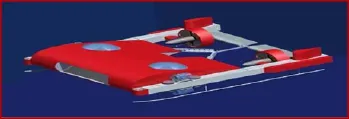
Fig.15 AUV powered glider(Andrea et al,2008)
4.4 XRAY glider
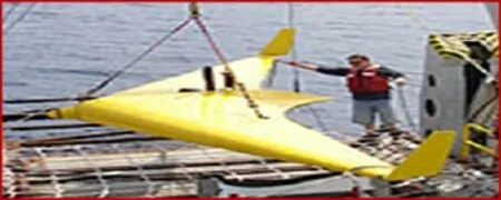
Fig.16 XRAY glider(APL,2007)
The military has developed an advanced underwater winged glider based on the air force’s flying wing design,the Liberdade XRAY as shown in Fig.16.This vehicle is being developed as a part of the Navy’s Persistent Littoral Undersea Surveillance Network (PLUSNet)system of semi-autonomous controlled mobile assets.PLUSNet uses unmanned underwater vehicles(UUVs)and (AUVs)to monitor shallow-water environments from fixed positions on the ocean floor or by moving through the water to scan large areas for extended periods of time(ONR,2006)[49].The vehicle is the largest of all of the underwater gliders(6.1 meter wing span),which has an advantage in terms of hydrodynamic efficiency and space for energy storage and payload.The glider’s primary function is to track quiet diesel-electric and the new fuel cell submarines operating in shallow-water.
According to military doctrine it can be deployed quickly and covertly and then stay in operation for months.It can be programmed to monitor large areas of the ocean(maximum ranges exceeding 1 000 km with on-board energy supplies).The glider is very quiet,making it hard to detect using passive acoustic sensing.The vehicle was designed for easy and rapid deployment and retrieval,as well as payload carrying capability,cross-country speed,and horizontal point-to-point transport efficiency which are better than existing gliders.Liberdade XRAY’s first major ocean test was performed in August 2006 in Monterey Bay,California, where it reported real-time via an 3.0 to 8.5 kHz underwater acoustic modem as well as with an Iridium satellite system while on the surface.The XRAY glider is hoped to achieve 1-3 knots cruise speeds,have a 1 200-1 500 km range,and be able to remain on-station up to 6 months in partial buoyant glides(D’Spain et al,2007)[50].
5 Wave glider overview
Wave glider is the first unmanned autonomous marine robot to only use the ocean’s endless supply of wave energy for propulsion(no manpower,no emissions,no refueling).It represents a technological leap from typical AUVs powered by motors and buoys with expensive mooring systems.The innovator of the wave glider,Roger Hine,started to work on a prototype in 2005.His main objective was to create a new type which could operate with no costly deep water mooring or shipping operations.The final design is a hybrid sea surface and underwater vehicle consisting of a submerged glider,attached via a tether,to a surface float.The subsur-face wing system,called the swimmer,has a frame on a longitudinal axis,and fins that rotate about the axis.The fins are laminar and the frame consists of a rigid bar.The fin system is comprised of 12 identical laminar fins. This subsurface glider looks similar to the Slocum glider except instead of one pair of wings there are six sets of wings down the vehicle’s side.
The vehicle is propelled by the submerged glider which can convert the vertical ocean wave motion energy into forward thrust.All other electrical devices are powered by solar panels attached to the float.Ion-lithium batteries are attached to the solar panels for power storage.As this vehicle was designed specifically to collect data from the ocean,the vehicle is capable of accommodating various kinds of sensors which may be used for different applications during missions(Hine et al,2007)[3].
In 2010,the vehicle was tested and operated in the ocean for 600 days,which exceeded the original target of 1 year.Therefore the design has proven to be a successful platform for the purpose of long term trials.A rising wave lifts the float,causing the tethered sub to rise.The articulated wings on the sub are pressed down and the upward motion of the sub becomes an up-and-forward motion,in turn pulling the float forward and off the wave.This causes the sub to drop,the wings pivot up and the sub moves down-and-forward as shown in Figs.17-18 and Tab.3.
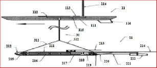
Fig.17 Basic design patent(Hine et al,2007)

Fig.18 Autonomous steering setup (Hine et al,2007)
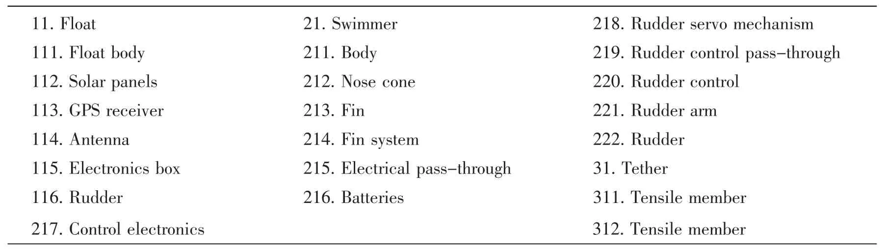
Tab.3 Basic design patent(Hine et al,2007)
This process is repeated again and again as long as there is wave motion on the surface even the smallest amount as shown in Fig.19. The vehicle moves quite slowly and high currents are a problem.The float contains a system for satellite communication and tracking which allows for steering using the rudder.The tethercomprises of a device to detect twisting and another device to correct the twisting.
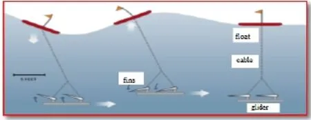
Fig.19 Wave glider method(The Wave Glider Tech,2012)
However,according to the data provided for wave glider,the maximum speed of the vehicle is only 2.25 knots,which is dominated by the magnitude of the wave.In this case,the wave glider is only suitable for missions with a long trial time.The magnitude of motion caused by propulsion is dominated by the difference between two wave crests.In this case,sea state is introduced as a parameter describing the general wave magnitude.
Wave glider is equipped with GPS and sophisticated computers for navigation and payload control with satellite communication systems and with state of the art ocean sensors to monitor and measure the environment around it.The specifications of the wave glider are shown in Tab.4.The wave glider is commonly fitted with an ADCP,an acoustic modem,vessel automation identification system receivers,passive acoustics for animal monitoring and a few other instruments to measure meteorological and oceanographic conditions.Because the wave gliders are mobile,they can be deployed from any port or harbor,complete their long missions and return back to any port or harbor to be serviced.
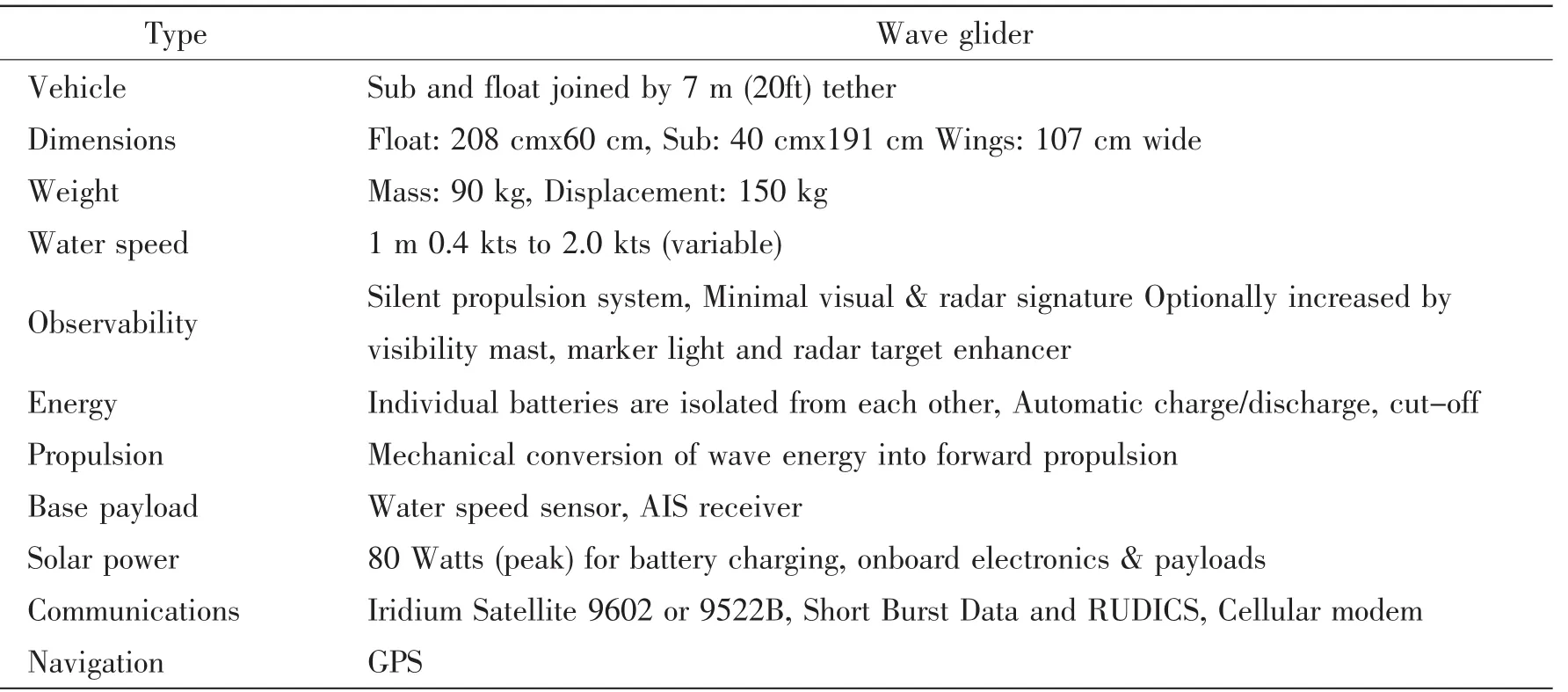
Tab.4 Specifications of wave glider(Liquid Robotics,2012)
6 Conclusions
Autonomous underwater vehicles are now being marketed as robust commercial vehicles for many industries,and of these vehicles underwater gliders are becoming the new tool for oceanographers.Satellites have provided scientists and marine specialists with measurements of the sea surface such as temperature since the late 1970s,and data via subsurface oceanographic moorings since the 1950’s.As stated before;gliders are one of the technological developments that are changing the way to observe the ocean and it is very exciting for us to be at the forefront of the application in ocean and climate science.This paper presents a survey of recent developments in underwater robotics,and on the current hot topic research and technological issues.
After discussing the various stages of AUV’s development,it can be concluded that thewave glider offers a cheaper,more economical,environmentally sound method of monitoring the seas compared to other AUVs.Wave glider is fit to replace many AUVs for a variety of applications.It could be used for intelligence,surveillance,monitoring exclusive economic zones for fishing and other economic resources that are very important to coastal countries.Wave glider does away with the large crews required for monitoring,cutting down the costs substantially,has a variety of applications in the commercial sector also can be used to find and research resources and fisheries.
Wave glider employs a multi-patented design that allows it to cost-effectively collect and transmit data gathered during year-long missions,over distances of thousands of miles or while holding station.Wave glider helps us address the biggest challenges our world faces,including global climate change,national security,hurricane&tsunami warning and offshore energy&resource management.
The wave energy propulsion system is powered purely by mechanical energy,which means that there will be no electrical power supplying the submerged part in terms of forward motion.This propulsion system is effective,since there is no energy lost from conversion.Therefore,the total energy lost,as a result of converting renewable energy into another form of secondary energy,can be eliminated.
At the very least,we hope to show that the progress in underwater robotics is catching up with the capabilities of the other robotic fields in producing original,differentiated,designs and systems tailored to the specific application needs,getting closer and closer to the autonomy expected by cognitive systems.Underwater robots are well on their way to take part in our everyday lives and activities.
The recommendations for a better future of the underwater gliders can be concluded in increasing the interest of ship owners and designers in the robotics market especially for the wave glider to replace many AUVs for a variety of applications and promote its use on a large scale,finally new research programs are needed to find efficient solutions for the problems associated with the applications of wave glider.
Acknowledgements
The authors would like to thank the College of Shipbuilding Engineering in Harbin Engineering University for their support in different tasks during the research that has led to this paper.
[1]Caccia M,Bono R,Bruzzone,Veruggio G.Unmanned underwater vehicles for scientific applications and robotics research: The ROMEO project[R].Marine Technology Society Journal,2000,34/2:3-17.
[2]Correia L,Steiger-Garcao A.An AUV architecture and world model[C]//5th International.Conf.on Advanced Robotics. Pisa,Italy,1991,2:1315-1320.
[3]Hine R G,Hine D L,Rizzi J D,Kiesow K A F,Burcham R,Stutz W A.Wave Power[P].Liquid Robotics Inc.,assignee. Patent 7371136,2007.
[4]Dive,Discover(2005).Dive and Discover:History of Oceanography[M/OL].Expeditions to the Seafloor.Web.24 Dec.2015.
[5]Data Buoy Types(2002)[R].JCOMM in Situ Observing Platform Support Centre.Web.24 Dec.2015.
[6]Bellingham J G,Goudey C A,Consi T R,Bales J W.A second generation survey AUV[J].IEEE Symposium.Autonomous Underwater Vehicle Technology,Cambridge,1994:148-155.
[7]AUV Laboratory at MIT Sea Grant(2012).History:AUV Laboratory at MIT Sea Grant[Z].Web.24 Dec.2015.
[8]Odyssey IV Robot Submarine by MIT|Geekie Gadgets(2008)[M/OL].Latest Technology.Web.24 Dec.2015.
[9]Liquid Robotics Fleet of Self-propelled,Solar-powered,Ocean-Going Robots Raises(2011)[M/OL].Web.24 Dec.2015.
[10]The Wave Glider Technology(2012).Ocean Robots Journey Across Pacific Ocean for New Scientific Discoveries[M/OL]. Web.24 Dec.2015.
[11]Christ R D,Wernli R L.The ROV manual:A user guide for observation class remotely operated vehicles[R].Butterworth &Heinemann,Oxford,2011.
[12]Conte G,Zanoli S M,Scaradozzi D,Calti A.Robotics techniques for underwater archaeology[J].Int.J Mechanics and Control,2009,10/1:45-51.
[13]Blidberg D R.The development of autonomous underwater vehicles(AUV);A brief summary[C]//International Conference Rob.Autom.(ICRA),Seoul,2001.
[14]Bellingham James G.An Overview of AUVs(2005)[M/OL].AUV Laboratory at MIT Sea Grant.Web.24 Dec.,2015.
[15]Pascoal A,Oliveira P,Silvestre C,Bjerrum A.MARIUS:an autonomous underwater vehicle for coastal oceanography[J]. IEEE Robotics and Automation Magazine,1997,4/4:46-59.
[16]Curtin T,Bellingham J,Capitovic J,Webb D.Autonomous oceanographic sampling networks[J].Oceanography,1993,6/3: 86-94.
[17]Yuh J,Negahdaripour S.Final report of the NSF workshop on future research directions on underwater robotics[C]//Maui, Hawaii,1994.
[18]Hagen P E,Storkersen N J,Vestgard K.HUGIN-use of UUV technology in marine applications[C].IEEE OCEANS’99 Conf.,Seattle,1999,2:967-972.
[19]Chance T S,Kleiner A A,Northcut J G.The autonomous underwater vehicle(AUV):A cost-effective alternative to deeptowed technology[M].Integrated Coastal Zone Management:Strategies and Tools,ICG Publishing,London,2000:65-69.
[20]Marco D B,Healey A J.Command,control,and navigation experimental results with the NPS ARIES AUV[J].IEEE J O-ceanic Eng.,2001,26/4:466-476.
[21]Bovio E,Schmidt H.The GOATS joint research project:Underwater vehicle networks for acoustic and oceanographic measurements in the littoral ocean[C]//SACLANTCEN Conf.Italy,2001:3-16.
[22]Allen B,Stokey R,Austin T,Forrester N.REMUS:A small,low cost AUV;system description,field trials and performance results[J].IEEE Oceans’97,1997,2:994-1000.
[23]Stokey R,Austin T,Allen B,Forrester N.Very shallow water mine countermeasures using the REMUS AUV:A practical approach yielding accurate results[C]//IEEE Conf.Oceans’01.Honolulu,2001,1:49-156.
[24]Ura T.Establishment of underwater technology research center at the institute of industrial science of the university of Tokyo and its activities on AUV development[C]//IEEE Int.Symposium,Underwater Technology UT’00.Tokyo,2000:140-145.
[25]Caiti A,Garulli A,Livide F,Prattichizzo D.Localization of autonomous underwater vehicles by floating acoustic buoys:A set-membership approach[J].IEEE J Oceanic Eng.2005,30/1:140-152.
[26]Leonessa A J,Mandello J,Morel Y,Vidal M.Design of a small,multipurpose,autonomous surface vessel[C]//IEEE OCEANS’03 Conf.San Diego,2003.
[27]Alves J,Oliveira P,Oliveira R,Pascoal A,Rufino M,et al.Vehicle and mission control of the DELFIM autonomous surface craft[C]//IEEE 14th Mediterranean Conf.Control Automation.Ancona,2006.
[28]Mies G.Military robots of the present and the future[M/OL].AARMS,2010,9/1:125-137.
[29]Bash J F.New ship technology and design[J].J Marine Tech.Soc.,2008,42/1:21-25.
[30]Hollings B,Pattiaratchi C B,Woo M,Hanson C E.Sustained oceanographic observations around Australia using autonomous Ocean Gliders[C]//IEEE Oceans’10 Conf.Sydney,2010:1-4.
[31]Bellingham J G.Autonomous ocean sampling network-II(AOSN-II):Integration and demonstration of observation and modeling(Final Report)[R].DTIC Report,2009.
[32]Leonard N E,Paley D A,Davis R E,Fratantoni D M,Lekien F,Zhang F.Coordinated control of an underwater glider fleet in an adaptive ocean sampling field experiment in Monterey Bay[J].Journal of Field Robotics,2010,27/6:718-740.
[33]Hyakudome T,Yoshida H,Ishibashi S,Sawa T,Nakamura M.Development of advanced Lithium-ion battery for underwater vehicle[C]//IEEE Underwater Technology Symposium.Tokyo,2011.
[34]Blidberg D R,Mupparapu S,Chappell S,Komerska R,Jalbert J C,Nitzelm R.The SAUV II(solar powered AUV)test results[C].IEEE Oceans’05.France,2005,1:545-550.
[35]Frolov S,Bellingham J,Anderson W,Hine G.Wave Glider-A platform for persistent monitoring of algal blooms[J].IEEE Oceans’11,Kona,2011.
[36]Yamamoto I.Research and development of past,present,and future AUV technologies[D].Master class in AUV Technology for Polar Science,National Oceanography Centre,Southampton,2006.
[37]Laschi C,Mazzolai B,Mattoli V,Cianchetti P,Dario P.Design of a biomimetic robotic octopus arm[M].Bioinspiration and Biomimetics,vol.4/1.IOP Publishing Ltd.,2009.
[38]Webb D C,Simonetti P J,Jones C P.SLOCUM:An underwater glider propelled by environmental energy[J].IEEE J O-ceanic Engineering,2001,26(4):447-452.
[39]Sherman J,Davis R E,Owens W B,Valdes J.The autonomous underwater glider Spray[J].IEEE J Oceanic Engineering, 2001,26(4):437-446.
[40]Griffiths G,Ed,Davis R E,Eriksen C C,Jones C P.Autonomous buoyancy-driven underwater gliders[R].In:Technology and Applications of Autonomous Underwater Vehicles Taylor and Francis,London,2002.
[41]Davis R E,Webb D C,Regier L A,Dufour J.The autonomous Lagrangian circulation explorer(ALACE)[J].J Atmos.O-ceanic Technol.,1992,9:264-285.
[42]APL.Applied Research Laboratory,Seaglider Fabrication Center,University of Washington[R].Seattle,WA,2008.
[43]Osse T J,Lee T J.Composite pressure hulls for autonomous underwater vehicles[J].Oceans,2007:1-14.
[44]Eriksen C C,Osse T J,Light R D,Wen T,Lehman T W,Sabin P L,Ballard J W,Chiodi A M.Seaglider:A long range autonomous underwater vehicle for oceanographic research[J].IEEE J Oceanic Eng.,2001,26(4):424-436.
[45]Osse T J,Eriksen C C.The Deepglider:A full ocean depth glider for oceanographic research[J].Oceans,2007:1-12.
[46]Graver J G.Underwater Gliders:Dynamics,Control and Design[D].Dissertation,Princeton University,Department of Mechanical and Aerospace Engineering,2005.
[47]Kawaguchi K,Ura T,Tomoda Y,Kobayashi Y.Development and sea trials of a shuttle type AUV ALBAC[C]//Proc.8th. International Symposium on Unmanned Untethered Submersible Technology.Durham,1993:7-13.
[48]Andrea Caiti,Vincenzo Calabrò,Daniele Meucci.Underwater Robots:Past,Present and Future[M].University of Pisa/I-taly,2008.
[49]ONR.Liberdade XRAY Advanced Underwater Glider[M/OL].ONR press release,retrieved on 15 September 2008. [50]D’Spain G L,Zimmerman R,Jenkins S A,Luby J C,Brodsky P.Underwater acoustic measurements with a flying wing glider[J].J Acoust.Soc.Am.,2007,121(5),Pt.2:3107. 自主水下航行器发展概述 ALAAELDEEN M.E.Ahmed1,段文洋2 (1.军事技术学院 船舶工程学院,开罗 埃及;2.哈尔滨工程大学 船舶工程学院,哈尔滨 150001) 自主水下航行器(AUVs)因其应用于海洋勘探而逐渐成为一个有趣的研究对象。波浪滑翔机是一种行驶于波浪表面的无人滑行器(SUV),它借助海洋能来推动自己,这对于典型的AUVs所采用的电机供能以及昂贵的锚链系统浮标供能来说,是一种技术上的重大跨越。该文讨论了最有效率的AUVs类型。第一部分为每一种类型的发展历程,第二部分为它们各自的技术特点。此外,波浪滑翔机作为应用于海洋部门的一种新型水下机器人,文中简要地给出它的过去,现在以及未来的发展概述。研究波浪滑翔机的意义在于证明它的效率以及实用性,进而取代诸多的AUVs来实现各种实际应用。而研究结果也表明波浪滑翔机确实可以应用于众多领域。对于海洋检测而言,相比于其他AUVs,波浪滑翔机提供了更廉价,更经济,更环保的作业模式,同时也不需要缆绳、船舶等海上作业服务。 自主水下航行器(AUV);水下滑行器;波浪滑翔机 U674.941 A ALAAELDEEN M.E.Ahmed,男,哈尔滨工程大学博士。现为埃及军事工程学院船舶工程专业讲师; U674.941 :A 10.3969/j.issn.1007-7294.2016.06.012 1007-7294(2016)06-0768-20 段文洋(1967-)男,哈尔滨工程大学船舶工程学院教授,博士生导师。 Received date:2016-03-09 Biography:ALAAELDEEN M.E.Ahmed,male,Ph.D.candidate,Corresponding author,E-mail:robyhadad@yahoo.com; DUAN Wen-yang(1967-),male,professor/tutor,E-mail:duanwenyang@hrbeu.edu.cn.
猜你喜欢
杂志排行
船舶力学的其它文章
- Identification of Non-stationary Excitation and Analysis of Transient Radiation Noise on Steering Engine
- Research on the Fracture Toughness for Ship Cracked Plates Based on the Accumulative Increment Plastic Deformation
- Forced Vibrations of a Submerged Finite Cylindrical Shell with an Internal Longitudinal Plate
- Study on the Structural Strengthening Design under the Ship-ice Collision Load
- Fatigue Reliability Analyses Considering Short Crack and Dwell Time Effects
- Prediction of Crack Growth Rates of a High Strength Titanium Alloy for Deep Sea Pressure Hull under Three Loading Patterns