Study on the Structural Strengthening Design under the Ship-ice Collision Load
2016-05-16,,,
,,,
(1.School of Naval Architecture and Ocean Engineering,Jiangsu University of Science and Technology,Zhenjiang 212003, China;2.Department of Naval Architecture,Ocean&Marine Engineering,University of Strathclyde,Glasgow,UK)
Study on the Structural Strengthening Design under the Ship-ice Collision Load
ZHANG Jian1,HE Wen-xin1,YUAN Zhi-ming2,CHEN Cong1
(1.School of Naval Architecture and Ocean Engineering,Jiangsu University of Science and Technology,Zhenjiang 212003, China;2.Department of Naval Architecture,Ocean&Marine Engineering,University of Strathclyde,Glasgow,UK)
In order to investigate the water media effect on structure response under ship-ice collision load,this paper presents a study on ship-ice collision considering the effect of water media for the first time.The ship-ice collision is simulated in aqueous medium and the coupling behaviors among the ship,water and ice were considered.The calculation model is applied to various working conditions of ship-ice collision calculation.The parametric study on the thickness of shell and diaphragm plates and the spacing of the frames is then conducted.The damage deformations,collision forces,structural energy absorptions varying with thickness of shell plate,thickness of the diaphragm plate and different spacing of frame are discussed.The capability and contribution of each major component in the shoulder of the ship on the resistance of ice loads are analyzed.This study can be used in improving anti-ice load ability of ship structure.
ship-ice collision in water media;ice model;structure response; strengthening design
0 Introduction
In the recent years,with the discovery and exploitation of oil and gas resources in arctic area as well as the development of Northern Sea Route(NSR),more and more attentions have been paid to the study on ship-ice collision in the field of naval architecture and ocean engineering.
Ship-ice collision has been a topic of interest among researchers especially those from Canada,Norway,America.Gagnon[1]investigated the ship-ice collision through both the experimental and numerical methods.However,the structural damage was not reported.Wang et al[2]used a coupled model to simulate ice-LNG collision.The floating ice model with inducted ice failure model,Liu et al[3-4]systematically studied the external and internal dynamics of a ship collision.They obtained the pattern of the energy dissipation during the collision by using a simplified method.They also simulated the ship-ice collision by a numerical method.Lee etal[5]conducted a collision test between a cylindrical ice and a grillage structure.Special efforts were put on the failure law of the ice model.Zhang et al[6]used both numerical and experimental methods to investigate the collision between the side grillage and ice to validate the feasibility of the ice material model,as well as the numerical method.
This paper based on finite element software,numerical simulation of ship-ice collision is conducted in the water media,The discussions are highlighted on the reinforcement of the structures in ice area.This study can be used in improving anti-ice load ability of ship structure design.
1 Ice numerical model
The accuracy of the numerical simulation depends on two aspects:the material model of both sides during the collision and method of numerical simulation.There are two kinds of materials mainly involving in ship collision:the steel hull and the ice.The material of hull is very mature already.However,The mechanical property of the ice is very complicated.One example is that ice fails in different modes under different strain rates(Liu et al)[7].At a low strain rate,the deformation of ice can be stimulated by the elastic-plastic theory and the nonrecoverable stage of deformation is dominated by the nonlinear properties.At a high strain rate, the ice deformation tends to be smaller.The stress-strain curve is linear to a large degree and the fragility of the ice takes the dominate role,and the ice is fractured,the failure mode(e.g. large scale and partly fragmentation and bending failure)varies.A transitional zone appears between the ductile zone and the brittle zone and is characterized by plastic deformation,many cracks shear failure and partly fragmentation.Schulson et al[8]investigated this strain rate effect,as shown in Fig.1 and suggested that ice stress tends to rise along with the strain rate until brittle failure appears.
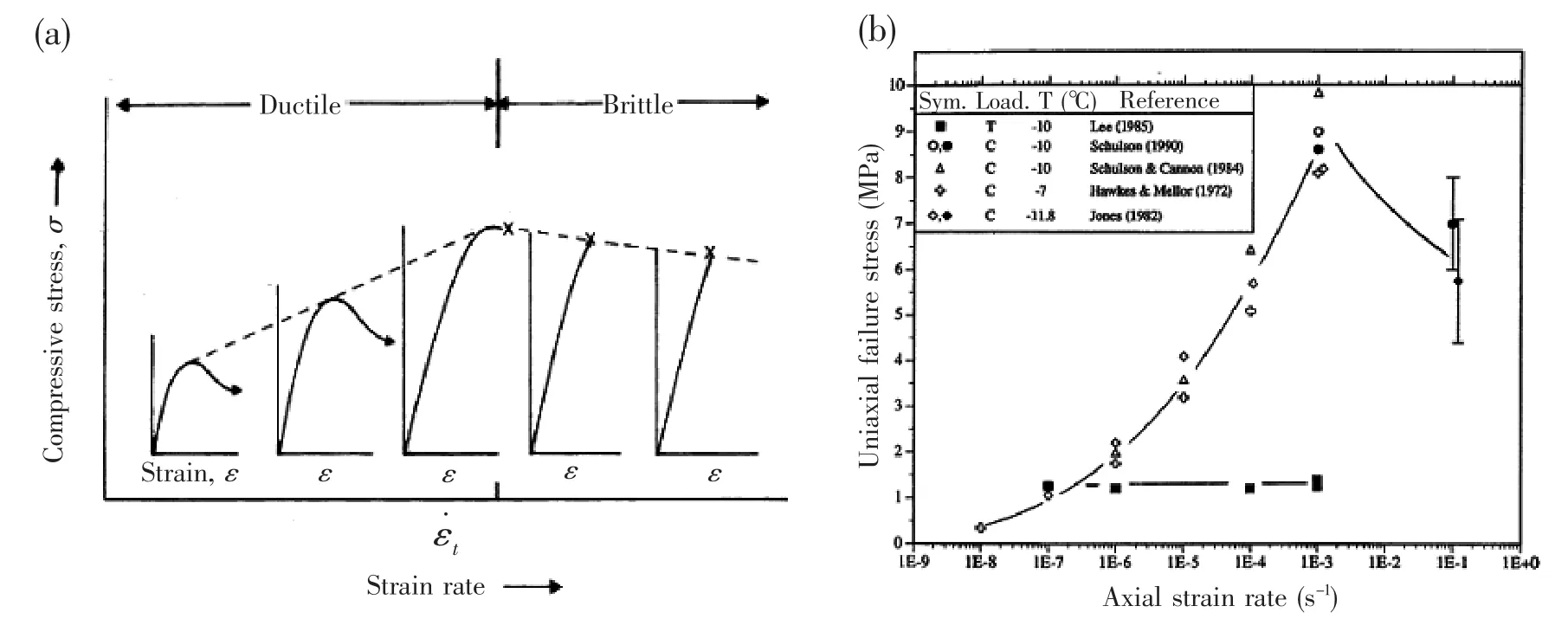
Fig.1 Ice strength plotted against strain rate
Based on the elastic-plastic theory,the expression of stress-strain relationship of constitutive equation derived from the yield curve formula,the yield curve is usually expressed by the stress tensor.In the case of the ship-ice collision,the ice is in the three-dimensional stressstate.In 1995,Gagnon and Gammon[9]made an ice triaxial experiment,based on the triaxial experiment data,Derradji-Aouat proposed iceberg elliptical yield closed line equation:

where τ is the Octahedral shear stress,τmaxis the minor axis of the ellipse,η and λ are the center coordinates of the ellipse,p is the hydrostatic pressure,pcis the major axis of the ellipse.
The iceberg material model,which is based on the‘Tsai-Wu’yield surface:


Some of the parameters have been customized,taking strain rate into consideration,the ice strain rate is set as field in the material model of ice.The ice material model as shown in Tab.1.In the reference[10],the findings of study had indicated,the ice material model and the numerical method can be used in numerical simulation for ship-ice collision.
Tab.1 The material parameters of ice
2 Numerical simulation of ship-ice collision in the water media
2.1 Ship-water-ice model
Recently,added water mass method is adopted by many researchers(Liu et al;Myhre; Wang et al)[3-4,11,2].However,the influence from the fluid resistance is neglected and the added mass is imposed to the ship hull mass.Therefore,the accuracy of the predictions is influenced. This section discusses the application of fluid-structure interaction method in the numerical simulation of ship collision.In order to investigate the water media effect on ship motions andthe fluid field after collision,the hybrid models of ship,water and ice have been established to simulate ship-ice collision in the water environment.
In order to simulate the infinite computational domain,the nonreflecting boundary condition is used.The coupling effects between shell plate and water media need to be defined in the model calculation. A hollow unit has to be established to guarantee that the waves and spatters are formed outside the computational domain and the gap in the stern can be filled immediately.The material property of the hollow unit is defined as fluid property.The finite element model of ship and water media is shown in Fig.2.
2.2 Flow distribution of water area
Fig.3 shows resultant velocity induced from the coupling effect of ship-water-ice.Fore body of the ship displaces water which forms waves on all sides.The advancing direction of the vessel could be modified after the ship-ice collision,which occurs at the fore part of the ship. From the top view we can see that the flow in the portside and starboard is asymmetrical and the movement of the ice has an indirect effect on water media.
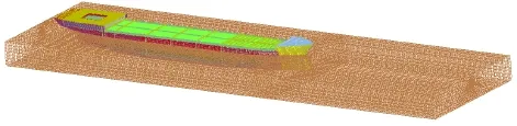
Fig.2 FE Model of ship and water
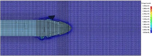
Fig.3 Resultant velocity under ship-water-ice coupling effect(top view)
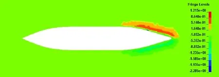
Fig.4 Transverse velocity of water
Fig.4 shows the horizontal flow field around the vessel.It can be found that the transverse component of velocity is asymmetry in the fore part of the vessel.The distribution of the transverse velocity in the plane of the vessel’s bottom plate could be influenced by the transverse impact from the ice.The flow at starboard can provide resistance,which can keep the vesselfrom rotation.Meanwhile,the flow at the starboard is squeezed by the vessel,which makes the velocity of the fluid on the starboard opposite to that on the portside.It can be concluded that ship-ice collision can influence the flow field around the vessel.
According to the analysis above,we can find that the fluid-structure interaction method can predict the ship motion in the water and the effect of transverse impact on flow field around vessel.This method can clearly simulate the ship-ice collision in the water media. Therefore,the fluid-structure interaction method can be used for further study on the anti-collision performance of ship structures under the ice loads.
3 Study on structure reinforcement design in ice area
According to the previous results on the comparison between the measurement and the numerical simulation,the simulation method for ship-water-ice model can be determined.This method takes the water media into consideration.In this section,this method will be extended to the study on structure reinforcement design.
3.1 Ship model
For ship-ice collision,the collision scheme must be determined first.This paper guarantees the total weight of the hull model,moment of inertia and center of gravity location and other physical properties are consistent with the real ship,then,a fine grid is taken to the area which is going to be contact,and the simplified method is adopted for the structure of the ship which is far away from the collision area.The finite element model of the ship is shown in Fig.5 and Fig.6.
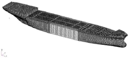
Fig.5 FE model of the ship
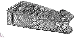
Fig.6 FE model of the bow and shoulder
The time step integration is the characteristics of the finite element technology,every step of the calculation required to satisfy the Courant criterion,this paper draws lessons from the domestic and international researchers,control the characteristic length of the hull structure model is about 250 mm,the grid size can ensure the precision of calculation,and can make the calculation efficiency to a certain extent.
The unit size of the calculation has a significant effect on calculation,unit type also has a significant impact on the result and the computation efficiency.Unit of ship finite element model with shell elements is defined by*SECTION_SHELL in LS-DYNA.Hughes-Liu S/R algorithm is chosen as its element algorithm.
In the process of ship-ice collision,there exist a lot of contact problems,contact bound-ary is constantly changing,so in the calculation we must continue to search the contact boundary,this paper uses contact erosion(Eroding_surface_to_surface).
3.2 Collision scheme
According to results by Zhang et al[6]and the recommended ice shape by DNV(DNV Technical Report)[12],three types of ice shape are simulated.It is found that the rhombic ice possesses the most destructive force against ship.In the present study,we select this type of ice to simulate the ship-ice collision problem.The simplified model and its collision zone are shown in Fig.7.
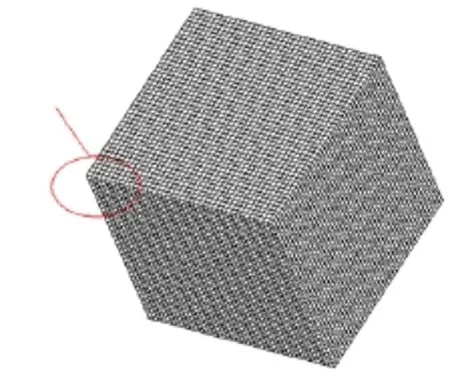
Fig.7 Ice model and impact location
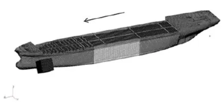
Fig.8 The sketch for the ship-ice collision
This paper focuses on a tanker navigating in ice region and the advancing speed is fixed at 8 m/s.The ice impacts the portside of the ship with the speed of 2 m/s at the angle of 30°. The impact angle here refers to the angle between top surface of cubic ice and base plane. The sketch for the ship-ice collision is shown in Fig.8.
There are mainly three parameters which could affect the reinforcement design:the thickness of the shell plate and diaphragm plate,and the spacing of the frame.The schemes of the impact are described as follows:
Plan I:Three cases of the thickness of the shell plate are taken into consideration.The thickness of cases A,B and C is 19 mm,22 mm and 25 mm,respectively.Since the collision region is limited to ice zone only,the shell plate should be only strengthened in ice belt region.The vertical strengthening range is from 2.7 m to 8.8 m.The thickness beyond the ice region is fixed at 12 mm.
Plan II:Three cases of the thickness of the diaphragm plate are taken into consideration. The thickness of cases A,B and C is 19 mm,22 mm and 25 mm,respectively.
Plan III:Two cases of the spacing of the frame are taken into consideration.The spacing of cases A and B is 0.8m and 2.4m,respectively.
3.3 Effects of shell plate thickness on ship-ice collision
3.3.1 Collision damage deformation
Through the comparisons in Fig.9,it can be found that the damage deformation of shell plate is mainly caused by tearing and membrane stretching strength.At the beginning,the large stress occurs at the collision area on the shell plate.And then the fracture occurs when the deformation goes beyond failure strain.At the same time,the ship hull has some velocity. The ice corner inserts into the inner structures and cuts the shell plate.The diaphragm plate,platform plate and some side shell frames yields,and then subjected to large deformation,instability and fracture.In terms of the damage level of the shell plate and inner structures,the most serious damage occurs in Case A,followed by Cases B and C.

Fig.9 Damage deformation of hull structure under three cases in Plan I
3.3.2 Collision force
Collision force exhibits nonlinearity and variability as the collision progresses.Qualitatively the process is as follows:(i)Collision force increases as the corner of the ice piece crushes against the hull and the contact area increases,(ii)Process continues,force increases as the shell plates and internal structure deform elastically,then plastically, (iii)Eventually hull structure fails(tearing and buckling)resulting in a force decrease,(iv)As the ship continues to advance,new structure comes into contact with the ice,force increases until the structure fails and the process repeats itself,(v)Further failure of the structure stops.
Fig.10 shows the time history of the collision force at different shell plate thickness.It can be found that at the initial loading stage,the deformation of shell plate increases gradually.The peak value occurs at the moment when the shell plate is being penetrated through.After that, there is a short period of unloading process.Then,the ice keeps cutting the inner structures in the portside of the hull during the relative motion between the ship and ice.As a result,the fracture of the strong components will cause the increase of the collision force,which can result in a violate fluctuation of the time history of the collision force.It can also be found that the collision forces are significantly influenced by the thickness of the shell plate.As the time is smaller than 0.6 s,although the curve of collision force represents the strong mode of vibration,it increases along with the thickness of shell plate generally.But as the time is greater than 0.6 s,the impact force will present to be low level earlier as the thickness increases.Besides,we find that the maximum collision forces are also influenced by the thickness of theshell plate.As the thickness increases,the maximum value keeps an increase trend.The damage moment will be delayed accordingly.The maximum collision force and the cracking moment are presented in Tab.2.
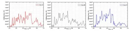
Fig.10 The time history of the collision force of Plan I

Tab.2 The comparison of the maximum collision force and plate cracking moment under different cases
3.3.3 Energy absorption
Fig.11 and Tab.3 show the energy absorption of all the components under different cases. It can be found that the shell plate is the main energy absorption component and it takes up to 50%of the total energy absorption.At the beginning stage,the energy absorption increases quickly due to the influence of the elastic deformation of the structure.As collision continues, the shoulder component deforms and absorbs energy gradually.As a result,the energy absorption will keep increase.As the time becomes greater than 0.8 s,the energy absorption tends to be stable,since the direction of the movement of the ice starts to deviate and the ice breaks away from the hull structures.It can also be found that during the same period of collision time,for shell plate,the percentage of the total energy absorption decreases as the thickness increases.The discrepancies between different components become small.
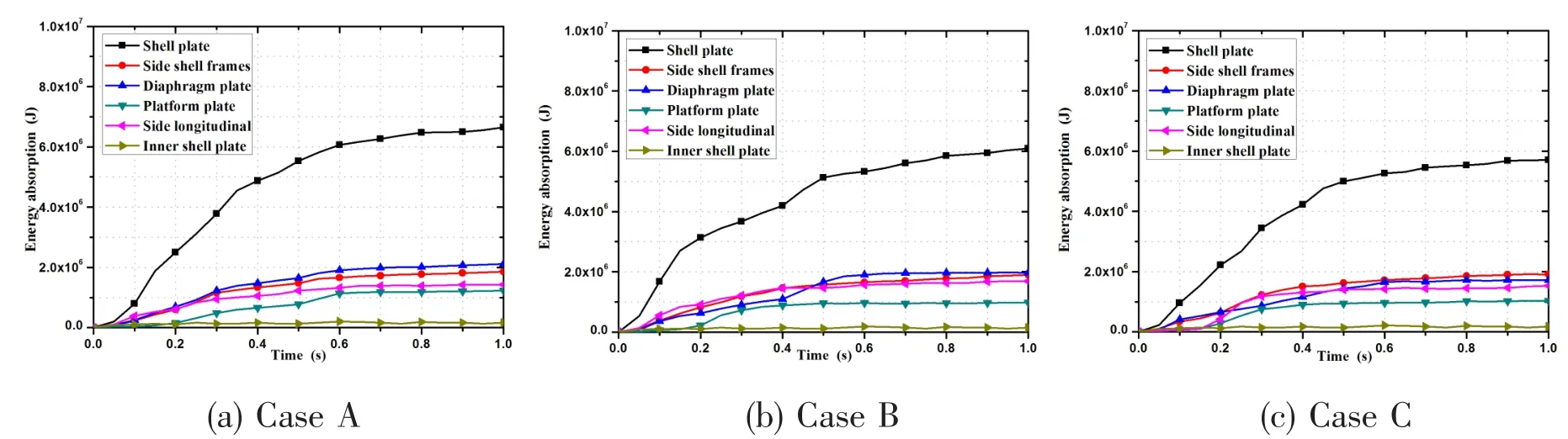
Fig.11 Curve of energy absorption under three cases in Plan I
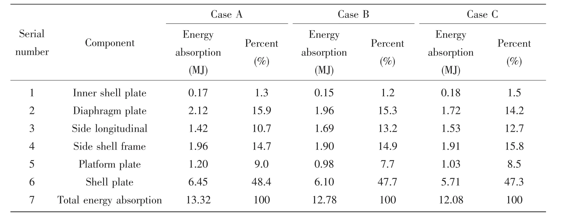
Tab.3 Energy absorption capacity of structural components
3.4 Effects of diaphragm plate thickness on ship-ice collision
From the previous results,we can see the percentage of the energy absorbing by the diaphragm plate is smaller than that of the shell plate.But it is still an important energy absorption component.
3.4.1 Collision damage deformation
Through the comparisons in Fig.12,it can be found that in terms of damage level of the shell plate and the internal side frame,the most serious damage occurs in Case A,followed by Cases B and C.Increasing the thickness of diaphragm plate can keep the shell plate from cracking,as well as stop the ice from embedding the inner structures of the ship hull.

Fig.12 Damage deformation of hull structure under three cases in Plan II
3.4.2 Collision force
Fig.13 shows the time history of the collision force at different diaphragm plate thickness. Tab.4 presents the maximum collision force in different cases.It can be found that the maximum collision forces are influenced by the thickness of the diaphragm plate.As the thickness increases,the maximum value keeps an increase trend.This suggests that increasing the thickness of diaphragm plate can improve shell plate’s capability of resistance to deformation.Besides,at the same impact height,the structure possesses a better anti-collision capacity if it can endure a higher collision force.
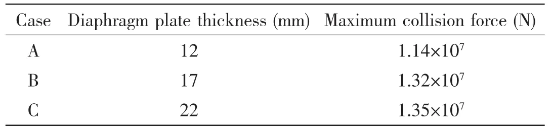
Tab.4 The comparison of the maximum collision force under different cases
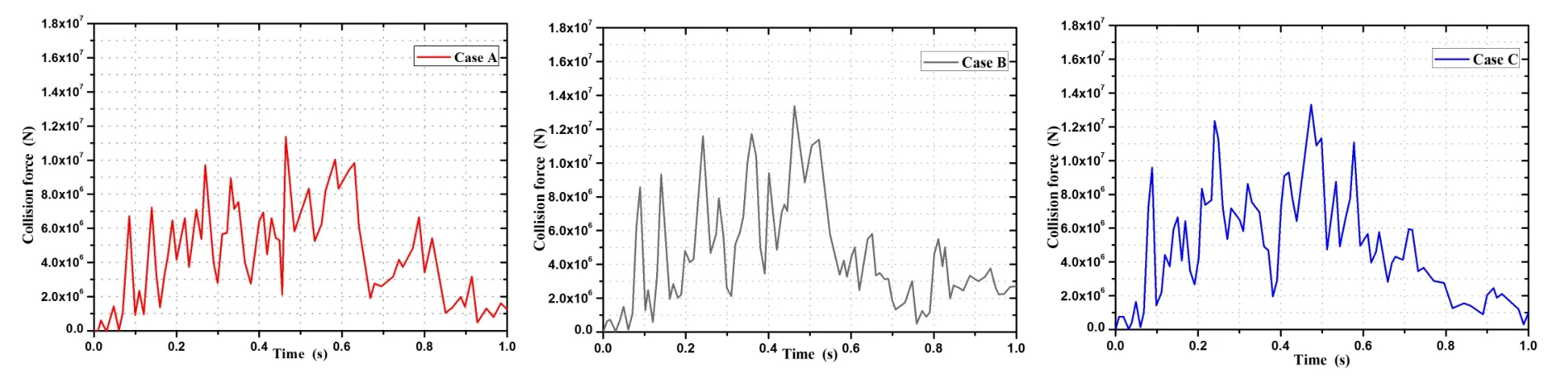
Fig.13 The time history of the collision force of Plan II
3.4.3 Energy absorption
Fig.14 and Tab.5 show the energy absorption of all the components under different cases. From the curve it can be found that as the thickness of diaphragm plate increases,the percentage of the energy absorption of the shell plate decreases,while the percentage of the diaphragmplate keeps a increase trend.The discrepancies between different components become smaller.Besides,the total energy absorption decreases as the thickness increases.As the diaphragm plate thickness increases from 12 mm to 22 mm,the total percentage of energy absorption decreases by 8%.In addition,based on the same increase of the mass of the diaphragm plate, the energy absorption of Case B decreases by 3.8%compared with Case A and for Case C,it drops by 4.2%compared with Case B.It can be concluded that in the present case study,the thickness of 17 mm is the optical design due to the collision damage deformation and energy absorption percentage.
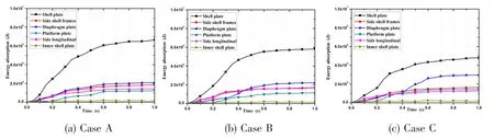
Fig.14 Curve of energy absorption under different cases in Plan II

Tab.5 Energy absorption capacity of structural components
3.5 Effects of frame spacing on ship-ice collision
The frame can strengthen the shell plate with respect to resist the collision and squeeze from the ice.It can be found from energy absorption results that the frame is also a key energy absorption component,which takes about 15%of the total energy absorption.
3.5.1 Collision damage deformation
From Fig.15,we can see the damage of hull structure varies with the spacing of the frame. The crevasse area in Case B is bigger than that in Case A.For Case A and Case B,the spacing of the frame is 0.8 m and 2.4 m.Since the spacing of the frame of Case A is much smaller,the capacity of support from the frame could be increased.At the beginning of the collision, the surface of the ship is squeezed.Most area of side frames and stringers start to deform and fail.Since the spacing of the frame in Case A is small,the number of frames in the same impact area is larger and more collision energy will be absorbed.As a result,the crack of theshell plate and the failure of the other components can be restrained.As the collision continues, the shell plates start to crack and the failure mode transforms into cutting.The frames,diaphragm plates,platform plates,side longitudinals and other components will resist ice intrusion together.
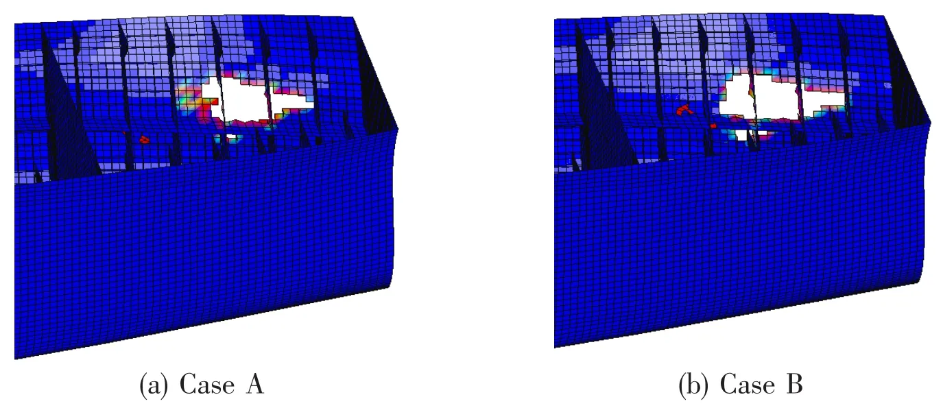
Fig.15 Damage deformation of hull structure under two cases in Plan III
3.5.2 Collision force
The time history of the collision force of Plan III is shown in Fig.16.It can be found that the peak value of collision force in Case A is higher than that in Case B.As the frame spacing increases,the supportability of the shell plate is reduced.Therefore,the shell plate could crack more easily.The maximum collision force and the cracking moment are presented in Tab.6.

Fig.16 Time history of collision force of Plan III
Tab.6 The comparison of the maximum collision force and plate cracking moment under different cases
3.5.3 Energy absorption
Fig.17 and Tab.7 show the energy absorption of all the components at different cases.It can be found that as the frame spacing decreases,the energy absorption percentage of the side frames increases and the discrepancies between different components become small.Besides, the total energy absorption increases as the frame spacing decreases.Compared Case B with Case A,the frame space increases from 0.8 m to 2.4 m,but the total energy absorption decreases by 18.5%.Therefore,when conducting the structural anti-collision design in the iceregion,the increase of the spacing of the frames can improve the total energy absorption.
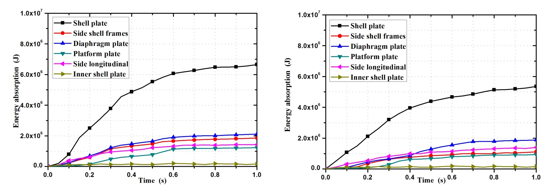
Fig.17 Curve of energy absorption under two cases in Plan III
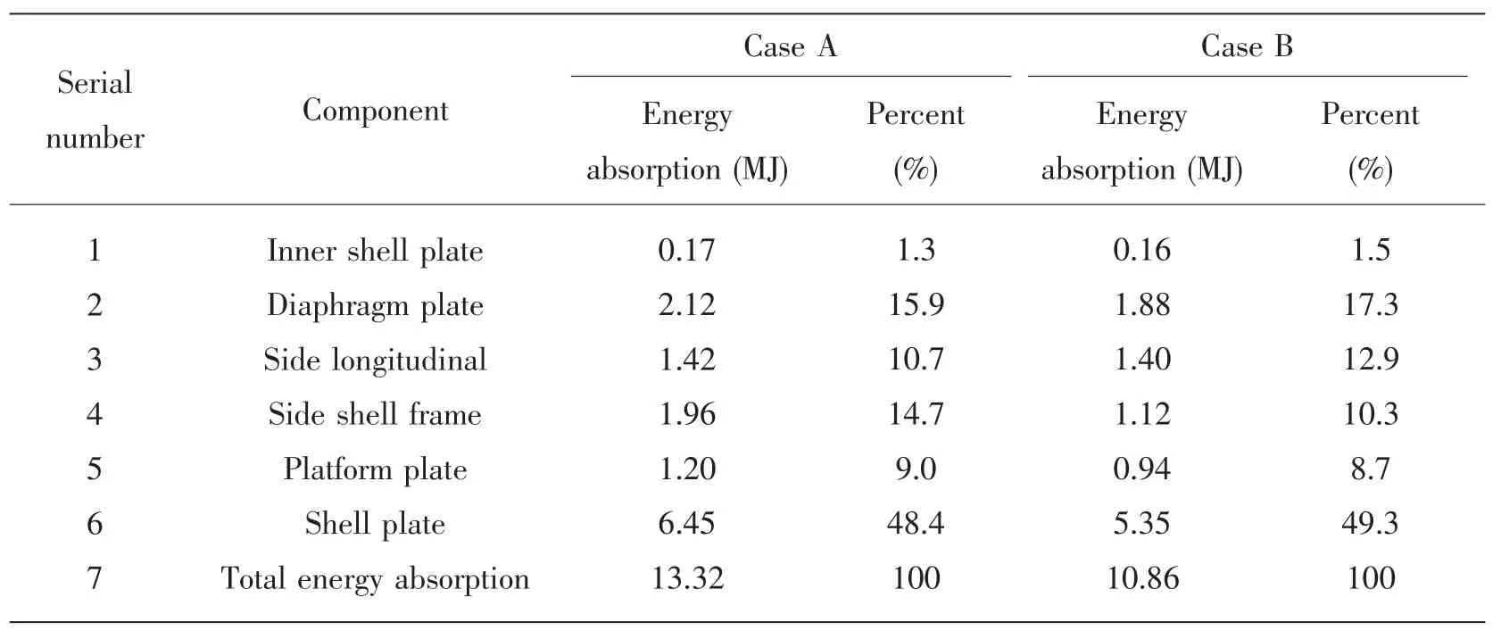
Tab.7 Energy absorption capacity of structural components
In summary,the thickness of the shell plate was taken 19mm,22 mm and 25 mm,the thickness of the shell plate increases,the structure crashworthiness performance is better,the damage deformation is smaller;shell plate thickness variations have a significant effect on the impact force,in general,maximum impact force increases with the increasing of the thickness; shell plate is the main energy absorbing component,the structure of the total energy absorption is inversely proportional to the increase of plating thickness,It can be concluded that in the present case study,the thickness of 25 mm is a better choice.The thickness of the diaphragm plate was taken 12 mm,17 mm and 22 mm,with the increase of the thickness of diaphragm plate,the range of damage of the shell plate and the internal skeleton will decreases;The biggest impact value is proportional to the thickness of diaphragm plate size;The total energy absorption of the ship structure is inversely proportional to the increase of the diaphragm plate thickness,it can be concluded that in the present case study,the thickness of 17 mm is a better choice.Frame spacing was taken 0.8 m and 2.4 m,the smaller the frame spacing,the more frames,the damage of other components will be reduced;when the frame spacing is 0.8 m,the peak value of pounding force will be larger;as the frame spacing decreases,the overall structure absorption can be increased,it can be concluded that in the present case study,0.8 m is a better choice.
4 Conclusions
From the results presented in this paper,the following conclusions can be drawn:
(1)The fluid-structure interaction method is an effective method to simulate the ship-ice collision in the water media.It can reflect the effect of the water on the ship motions.
(2)Shell plate is the main energy absorbing component.It takes up around 50%of the total energy absorption,followed by the side supporting components,such as diaphragm plate, platform plate,side shell frame and side longitudinal.
(3)The discrepancies of the energy absorption capacity among the diaphragms plate,platform plate,side longitudinal stiffness,side shell frame and shell plate can be reduced by increasing the shell plate and diaphragm plate thickness,as well as reducing the spacing of frames.
(4)In the design of the anti-collision structures,we need to consider the relationship between the damage deformation and energy absorption,so as to find the optimal thickness of the shell plate in ice region.In the premise of the limitation of the structural weight,we can increase the thickness of the diaphragm plate and reduce the spacing of the frames to achieve a smaller deformation and better energy absorption.
[1]Gagnon R.First results of numerical simulations of bergy-bit collisions with the CCGS terry fox icebreaker[C]//In:Proc. of the 18th Int.Ass.for the Hydo-Enviroment Eng.and Research(IAHR)on ice,Aug.28-Sep.1 2006,Sapporo,Japan, 2006.
[2]Wang B,Yu H C.Ship and ice collison modeling and strength evaluation of LNG ship structure[C]//In:OMAE.shanghai, China,2008.
[3]Liu Z H,Amdahl J,Løset S.A parametric study on the external mechanics of ship/iceberg collision[C]//In:Proceedings of the ASME 2010 29th International Conference on Ocean Offshore and Arctic Engineering.Shanghai,China,2010(4): 741-749.
[4]Liu Z H,Amdahl J,Løset S.Integrated numerical analysis of an iceberg collision with a foreship structure[J].Marine Structures,2011(24):377-395.
[5]Lee S G,Lee J S.Structural safety assessment in membrane-type CCS in LNG under iceberg collision[C].In:Royal Institution of Naval Architects International Conference-International Conference on Ship and Offshore Technology:Ice Class Vessels,2009:69-81.
[6]Zhang J,Wan Z H,Chen C.Research on structure dynamic response of bulbous bow in ship-ice collision load[J].Journal of Ship Mechanics,2014,18(1):106-114.
[7]Liu Z H,Amdahl J,Løset S.Plasticity based material modelling of ice and its application to ship-iceberg impacts[J]. Cold Region Science and Technology,2011,65:326-334.
[8]Schulson E M.Brittle failure of ice[J].Engineering Fracture Mechanics,2011(68):1839-1887.
[9]Gagnon R E,Gammon P H.Triaxial experiments on iceberg and glaciers ice[J].Glaciology,1995,41(1):39-54.
[10]Zhang Jian,Wan Zhengquan,Huang Jinhao,Yin Qun.Research on numerical simulation and model test of collision between side grillage and icebergs[J].Journal of Ship Mechanics,2014,18(4):424-433.
[11]Myhre S A.Analysis of accidental iceberg impacts with membrane tank LNG carriers[D].The Master Dissertation of Norwegian University of Science and Technology,2010:121-135.
[12]DNV Technical Report 2006-0672.Ice Collision Scenario[R].2006.
船冰碰撞载荷下船舶结构加强方案研究
张 健1,何文心1,元志明2,陈 聪1
(1.江苏科技大学 船舶与海洋工程学院,江苏 镇江212003;2.英国斯特拉斯克莱德大学,英国,格拉斯哥)
为了探究水介质对船—冰碰撞结构响应的影响,文章首次对考虑水介质中的船—冰碰撞问题进行了研究。模拟了船舶与冰体在水介质中的碰撞场景,研究船—水—冰三者共同耦合作用对船—冰碰撞的影响。将该计算方法应用于船—冰碰撞的多种工况计算,对比分析了增加外板厚度、横隔板厚度以及肋骨间距等多种加强方案对船体结构响应的差异。揭示了碰撞区域的损伤变形、碰撞力、结构吸能随外板厚度、横隔板厚度和肋骨间距的变化而变化的规律,分析了船舶肩部各主要构件对于抵抗冰载荷作用的能力及贡献。所得结论对于进行冰区船舶结构设计具有参考作用。
水介质下船冰碰撞;冰模型;结构响应;加固设计
U661.4
A
张 健(1977-),男,博士,江苏科技大学副教授,研究生导师;
U661.4
A
10.3969/j.issn.1007-7294.2016.06.008
1007-7294(2016)06-0722-14
何文心(1992-)女,江苏科技大学硕士研究生;
元志明(1985-),男,博士,英国斯特拉斯克莱德大学讲师,研究生导师;
陈 聪(1990-),男,江苏科技大学硕士研究生。
Received date:2016-03-30
Founded item:Supported by National Natural Science Foundation of China(Grant No.51579121);Jiangsu Provincial Department of Education Natural Science Foundation of Major Project(Grant No.15KJA580002); Ship Industry Pre-research Foundation(13J1.5.1)
Biography:ZHANG Jian(1977-),male,Ph.D.Associate professor of Jiangsu University of Science and Technology,
E-mail:justzj@126.com;YUAN Zhi-ming(1985-),male,Ph.D.lecturer/tutor of University of Strathclyde,UK.
猜你喜欢
杂志排行
船舶力学的其它文章
- Overview on the Development of Autonomous Underwater Vehicles(AUVs)
- Identification of Non-stationary Excitation and Analysis of Transient Radiation Noise on Steering Engine
- Research on the Fracture Toughness for Ship Cracked Plates Based on the Accumulative Increment Plastic Deformation
- Forced Vibrations of a Submerged Finite Cylindrical Shell with an Internal Longitudinal Plate
- Fatigue Reliability Analyses Considering Short Crack and Dwell Time Effects
- Prediction of Crack Growth Rates of a High Strength Titanium Alloy for Deep Sea Pressure Hull under Three Loading Patterns