Identification of Non-stationary Excitation and Analysis of Transient Radiation Noise on Steering Engine
2016-05-16
(China Ship Scientific Research Centre,Wuxi 214082,China)
Identification of Non-stationary Excitation and Analysis of Transient Radiation Noise on Steering Engine
LIN Chang-gang,ZOU Ming-song,JIAO Hui-feng,LIU Peng
(China Ship Scientific Research Centre,Wuxi 214082,China)
When an underwater vehicle changes directions by the steering engine,the opening process of steering engine generates a high transient radiation noise.So before a steering engine is installed in an underwater vehicle,it is necessary to estimate transient radiation noise of the steering engine.In this paper,based on the vibration test of the steering engine for an underwater vehicle, the transient maximum and mean excitation forces acting on the positions of connections between steering engine and experimental setup are calculated indirectly by least square method of load identification in frequency domain and STFT signal processing method.In addition,the accuracy and feasibility of results are verified.Cylindrical shells with ribs are basic structures which are used in underwater vehicles.By taking excitation forces results as an approximate input,a cylindrical shell whose two tips are simply supported is chosen as calculation model of a cabin of underwater vehicle,and the transient maximum and mean radiation noise of shells are calculated separately to estimate the steering engine’s characteristics of noise sources.A non-stationary STFT signal processing method to evaluate transient radiation noise of steering engine is provided.
steering engine;transient radiation noise;STFT(short-time Fourier transform); excitation forces;cylindrical shells
0 Introduction
With the continuous development of vibration noise reduction technology,the stationary acoustic radiation of underwater vehicle is getting smaller,but it is difficult to accurately predict and control the transient noise due to its non-stationary and random characteristics,therefore,the study of the transient radiation noise is of great significance.When an underwater vehicle changes courses by steering engine,the opening of steering engine will make the mechanical vibration and the transient radiation noise around the flow field suddenly become larger.In order to prevent the transient radiation noise from being too large in the steering engine opening condition,before the steering engine installation,it is necessary to evaluate its source vibration characteristic by test.In general,the test method which is commonly used in engineering is to install the steering engine in a vibration bench,although that is different from installation in the underwater vehicle,the source excitation characteristics of steering engine arethe same.So,the focus is put on a kind of evaluation method about source transient vibration characteristics of steering engine when it is opening.
Exciting force characteristics are often needed for machinery noise evaluation,but in engineering practice,it is difficult to measure for the external loads acting on the structure directly due to the limitation of actual environment.So the load identification technology to estimate indirectly exciting force characteristics of the equipment is needed.Load identification methods include frequency domain method and time domain method.Time domain research method started relatively late,by contrast,frequency domain method is relatively mature,and has made great progress.
As early as the 1970 s,by measuring the frequency response function matrix and vector of the acceleration response,dynamic load of main shaft of helicopter was estimated indirectly by Barlett Jr et al[1]and Giansante et al[2].The reciprocity method was put forward by Yap et al[3-5]to estimate force and moment of the points between the equipment and the support structure indirectly,and estimated results were in a good agreement with experimental measurement results.
In China,the detailed study on the source characteristics of mechanical equipment vibration test method had been carried on in Yuan’s doctoral thesis[6].On the basis of the frequency response function direct inversion,one least square method which was more practical and more accurate in the frequency domain load identification was used,and two different estimation methods based on the base admittance characteristics for elastic and rigid mounting equipment were also proposed by him.In addition,the more targeted error matrix method was set up by him to obtain the singular value when encountering frequency response function matrix inversion pathological problems by the singular value decomposition technique.On the basis of predecessors’virtual force model,the ill-posed problems of the frequency response function matrix inversion were solved by improved division regularization method by Lu[7]et al, and the feasibility and the accuracy of exciting force estimation were verified by motor model experiment.
Firstly,the vibration test for a steering engine of an underwater vehicle being built is finished in this paper.Secondly,On the basis of the predecessors,the least squares method in the frequency domain load identification and short-time Fourier transform of signal processing technology is used to estimate indirectly transient maximum exciting force and mean exciting force at the foot points of steering engine respectively.At last,the feasibility and the accuracy of the estimation results are verified.Because the ribbed cylindrical shell is the most widely used form of the underwater vehicle,a simply supported ribbed cylindrical shell between both ends of a segment of underwater vehicle as calculation model and the estimated exciting force of results as input of acoustic radiation calculation,the transient maximum and mean radiation noise are calculated respectively to estimate source characteristics of steering gear,and the focus is on putting forward an evaluation method on the transient radiation noise when the steering engine is opening.
1 Estimation of steering engine exciting force characteristics
1.1 Estimating process of source exciting force
Specific estimating processes are as follows:
(1)Before the equipment has not been installed in a experimental setup,the frequency response function of the experimental setup should be measured,and frequency response function matrix tested is expressed as[A].It is important to note the number of response points should be more than excited points so that the least square method could be applied.
(2)The equipment is started to keep the equipment in a state of normal operation,then each response point vibration response is measured at this time.Each response point should be the same as each frequency response function measured point.The results of some response points are selected as response vector{a}to estimate exciting force.
(3)Solution of the exciting force.
According to the relationship between exciting force and response:

The estimation of exciting force:

There exists ill-posed problem during frequency response function matrix inversion,so exciting force estimation error is large.To solve the ill-posed problems,truncated singular value method and Tikhonov regularization method[7]are commonly used methods.Based on Ref.[6], the truncated singular value method is used to solve this problem in this paper.
(4)Validation of the exciting force
Frequency response function matrix and the acceleration response vector of the remaining response points are selected,and a set of exciting force estimated vector{F}and frequency response function matrix[A]consisted of the remaining response points are substituted into formula(1)to solve the acceleration response.By comparing with the results of the measured acceleration,the accuracy for the estimation results of exciting force is validated.
2 Steering engine vibration test
2.1 A measure of the frequency response function
Firstly,the locations of the excited points and structural response points are selected.Excited points should be at foot positions of machine,while there is no requirement for response points except that the number of response points should be more than excited points so that least square method could be applied.Four excitation points at the foot of steering engine are A,B,C,D,respectively,response points are 1,2,3,4,respectively and other response points are 5,6,7,8,as shown in Fig.1.
Measurement steps of frequency response function:
(1)An acceleration sensor is decorated at each measuring point position,and the sensor and the multi-channel data collector are connected with program-controlled amplifier(Fig.2). The serial number of each sensor corresponding with connection channel is recorded.

Fig.1 The positions of test points

Fig.2 The vibration test about the system of steering gear
(2)Excited point A is knocked by a force hammer,and this excited point is hit 10 times, then the acceleration sensor signal is measured and recorded,at the same time,the hammer exciting force signal is recorded.
(3)According to the step(2),excited points B,C,D are knocked respectively,and exciting force signal of the force hammer and the acceleration sensor signal of the eight measured points are recorded.
(4)The frequency response function of the system is obtained by dealing with data.
Before frequency response function was measured,harmonic response analysis by ANSYS software had been completed for the whole vibration system in this paper,and the finite element model of the whole system is shown in Fig.3.The finite element numerical calculation results of the frequency response function are compared with test results by measured frequency response functions.When point A is knocked,the frequency response function results of response point 5 is shown in Fig.4.

Fig.3 The FEM model of the system

Fig.4 Comparison of frequency response functions of point 5
It can be known that both results are in a good agreement,and the results of numerical simulation can provide guidance for testing measurement to ensure measurement results be accurate and reliable.
2.2 Non-stationary signal processing
Vibration acceleration signal at response point 5 is shown in Fig.5.

Fig.5 The acceleration signal of point 5

Fig.6 STFT time frequency spectrum
We can know from the above figure that steering engine operating process is an non-stationary process in this test,and the vibration energy of the signal mainly concentrates in 6~9 seconds after the steering engine opens.The time-varying non-stationary signal[8]can not be well analyzed by the classic signal processing technology,so it is necessary to study the whole and the local characteristics in the time domain and frequency domain for non-stationary signals in order to grasp the whole and the local signal at the same time and extract more information.That can not be achieved only through the time domain or frequency domain analysis.
Short-time Fourier transform(STFT)is widely used in the analysis of non-stationary signal[9].In this method,non-stationary signal is composed of a series of short stationary signal, and short-time characteristics are available by window function,regarding the signal in window as be quasi-stationary signal,and then,the time-frequency spectrum of the signal is available by Fourier transform of each section of the signal.Therefore,short-time Fourier transform is also called as window Fourier transform.
For a given non-stationary signal,a new signal is defined through the window function

The signal is the function based on parameter t in the time period τ.Fourier transform of the new signal is called short-time Fourier transform of the original signal,namely:

Because the characteristics of a period of time of the original signal x()tnear the time t are highlighted by the new signalthe original signal in the frequency distribution of the time is reflected by the Fourier transform of the new signal.
In this paper,STFT method is used,and the elements in response vector{a}can be written as[6]:

The time frequency spectrum of the measurement signal after short-time Fourier transform is shown in Fig.6.
The time-frequency vibration characteristics of the whole process can be clearly observed from Fig.6.The steering engine is accelerating during 1~6 s.With the speed of the steering engine increasing,the vibration frequency of the signal is approximately linearly increased from about 200 Hz to the stable vibration 450 Hz;The steering engine is vibrating stably under the rated speed during 6~9 s and the vibration frequency of the signal is in about 450 Hz,and period signal of vibration amplitude is the largest during this time;The steering engine decelerates after 9 s,and the vibration frequency of the signal is also in about 450 Hz,but the vibration amplitude of the signal decreases obviously.
Two kinds of evaluation methods of signals are given in this paper due to the non-stationary characteristics of the signal.Firstly,in order to get maximum transient radiation noise when steering engine is opening,the strongest vibration energy signal in all STFT subsection signals is regarded as the first assessment signal;Secondly,the mean value of the all STFT subsection is regarded as the second assessment signal.Two kinds of signal force spectrum results are shown in Figs.7 and 8,respectively.

Fig.7 The amplitude and phase of acceleration curves

Fig.8 The amplitude and phase of acceleration curves
2.3 Exciting force estimation results of steering engine
Two kinds of signal estimation results in excited point A are shown in Figs.9 and 10,re-spectively.

Fig.9 The amplitude and phase response of excited point A

Fig.10 The amplitude and phase response of excitation point A
2.4 The validation and error analysis of the exciting force results
The response points 1~6 are selected to estimate the exciting force for steering engine using the formula(2)in this paper,and the response points 7 and 8 are selected to verified the accuracy of the exciting force results using the formula(1),and the verification results of two kinds estimation signals are shown in Figs.11 and 12.
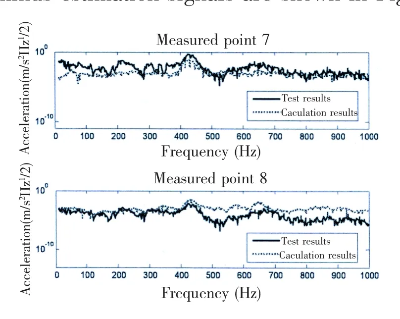
Fig.11 The verification of transient maximum excitation forces

Fig.12 The verification of mean excitation forces
It can be seen by comparing the calculation results with test results that they are in a good agreement on the whole,and the accuracy and feasibility of the exciting force results are verified.
But there is still a certain amount of error between calculation results and test results, which can be resulted from the following reasons:firstly,the signal to noise ratio is low due to the influence of the test environment;secondly,the influence of the longitudinal and lateral excitation force is ignored in this paper;thirdly,the verification points 7 and 8 are far away from the excited points.
3 Acoustic radiation calculation for steering engine
The fluid-solid coupling vibration between the hull and the flow field will be caused by the exciting force,resulting into the surrounding radiation noise.Because cylindrical shells with ribs are basic structures which are used in underwater vehicles,a cylindrical shell whose two tips are simply supported is chosen as the calculation model of a cabin in the underwater vehicle to estimate the radiation noise.It assumes that the stiffness of steering engine base is large enough,so the exciting forces are equivalent to those acting on the cylindrical shell directly,and then the radiation noise is calculated based on elastic thin shell theory and elastic coupling theory,using modal analysis method.
3.1 Vibration and sound radiation of underwater cylindrical shell
According to the Ref.[11],equations of motion based on Donnell model of elastic cylindrical shell are shown below[10-11]:
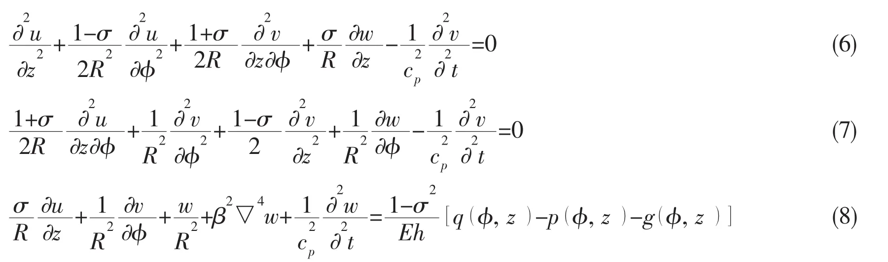
In the formulae:R,h are the radius and the thickness of the cylindrical shell,respectively;z, φ are the axial and circumferential coordinate;u,v,w are axial,circumferential and radial displacement component,respectively;E,σ are cylindrical shell material Young’s modulus, Poisson’s ratio,respectively;k0andare longitudinal wave number and wave velocity,respectively;ρ is the density of shell;qare the force acting on cylindrical shell,sound pressure and the force acting on ribs.
The modal superposition method is used,and the axial,circumferential and normal displacements are recognized as the following forms:

where kmis the axial wave number,and n is circumferential wave number.According to the simply supported boundary conditions[12]at both ends of cylindrical shells:

At the same time,sound pressure p both satisfies wave equation and the outer boundary conditions,that is medium particle vibration velocity and normal vibration velocity on the surface of the cylindrical shell are equal,and it can be expressed as:

where c0is the speed of sound in water.
Finally,coupling vibration equation of circular cylindrical shell can be expressed as:

In this paper,the radiation noise resulting from steering engine can be equivalent to incoherent superposition of four single-point excitation,and by supposing that the exciting force actat the point z=0,φ=0,the exciting forces results can be obtained by vibration measuring test.
The modal vibration velocity W˙mncan be available by solving Eq.(12),and the radiation sound power can be available if the impedance and modal vibration speed results are substituted into the calculation formula of radiation sound power:

3.2 Numerical example
A cabin section in the underwater vehicle is taken as an example,and the radius of cylindrical shell is R,length is 4.6R,thickness of the shell is 0.086R,the structural loss factor is 0.02.
The source levels of two kinds of signal are shown in Fig.13.
By the calculation,total source levels of two kinds of signal are 140 dB and 124 dB,respectively. The results of the transient radiation noise are higher than the overall average radiation noise by about 20 dB when the steering engine is operating.So it is necessary to study the whole and the local characteristics for non-stationary signals.
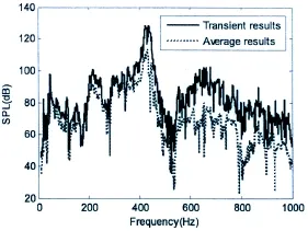
Fig.13 Comparison of source levels
4 Conclusions
This paper is based on the vibration test of the steering engine for an underwater vehicle, and the transient maximum and mean excitation forces in the positions of connections between steering engine and experimental setup when the steering engine is opening are calculated indirectly by least square method of load identification in frequency domain and STFT signal processing method.In addition,the accuracy and feasibility of results are verified.The transient maximum and mean acoustic radiation of the shell are calculated separately to estimate the steering engine characteristics of noise sources,the results show that it is necessary to study the whole and the local characteristics for non-stationary signals.The focus is on a kind of evaluation method about transient acoustic radiation of steering engine using non-stationary STFT signal processing method in this paper.
[1]Barlett Jr F D,Flannelly W G.Model verification of force determination for measuring vibration loads[J].Journal of the American Helicopter Society,1979,19(4):10-18.
[2]Giansante N,Jones R,Galapldas N J.Determination of in-flight Helicopter Loads[J].Journal of the American Helicopter Society,1982,27(3):58-64.
[3]Yap S H,Gibbs B M.Structure-borne sound transmission from machines in building,Part 1:Indirect measurement of force at the machine-receiver interface of a single and multi-point connected system by a reciprocal method[J].Journal of Sound and Vibration,1999,222(1):85-98.
[4]Yap S H,Gibbs B M.Structure-borne sound transmission from machines in building,Part 2:Indirect measurement of force and moment at the machine receiver interface of a single point connected system by a reciprocal method[J].Journal of Sound and Vibration,1999,222(1):99-113.
[5]Yap S H,Su J X.The measurement of the structural dynamic characteristics of floors with installed machines[J].Applied Acoustics,1997,52(2):105-124.
[6]Yuan Chunhui.A study on the test approaches of characterization of machinery as vibrational sources[D].Wuhan:Huazhong University of Science and Technology,2006.
[7]Lu Dingding,He Lin,Cheng Guo,Nie Yongfa.Research on pseudo-forces method used in characterization of machine force[J].Journal of Ship Mechanics,2013,17(10):1169-1175.
[8]Zhang Xusheng,Sun Jinwei,Zhao Xinmin.Analysis of non-stational signals by time-frequency analysis methods[J].Journal of Astronautic Metrology and Measurement,1995,15(5):34-41.
[9]Liu Benyong.An introduction to nonstationary signal analysis[M].BeiJing:National Defense Industry Press,2006.
[10]He Zuoyong.Structual vibration and acoustic radiation[M].Harbin:Harbin Engineering University Press,2001.
[11]Burroughs C B.Acoustic radiation from fluid-loaded infinite circular cylinders with doubly periodic ring supports[J].A-coust.Soc.Am.,1984.
[12]Chen Tieyun,Chen Bozhen.Ship structural mechanics[M].Harbin:Harbin Engineering University Press,2007.
[13]He Bingrong.Vibration and acoustic radiation of submerged ribbed finite elastic cylindrical shell[D].Shanghai:Shanghai Jiao Tong University,1999.
[14]Qi Libo,Zou Mingsong.Acoustic radiation of stiffened cylinder with different shells[J].Journal of Ship Mechanics,2013, 17(6):697-701.
舵机非稳态激励识别及瞬态声辐射分析
林长刚,邹明松,焦慧锋,刘 朋
(中国船舶科学研究中心,江苏 无锡 214082)
当水下航行器利用舵机改变航向时,舵机的开启会产生很大的瞬态辐射噪声。因此,在舵机安装之前,有必要对舵机的源特性进行评估。文章基于某水下航行器的舵机振动测试试验,应用频域载荷识别中的最小二乘法方法和短时傅里叶变换的信号处理技术,对舵机操舵过程中舵机与试验台架连接的机脚点处的瞬态最大激励力和整体平均激励力分别进行了间接估算,并将估算结果的准确性和可行性进行了验证。考虑到加肋圆柱壳是水下航行器的基本结构形式,文中将估算的激励力结果作为辐射声计算的近似输入,以一个两端简支的加肋圆柱壳体作为水下航行器的一个舱段的计算模型,分别计算了舵机操舵过程中水下瞬态最大和整体平均辐射噪声的大小,提出了一种利用短时傅里叶变换信号处理技术来评估舵机水下瞬态辐射噪声的方法。
舵机;瞬态辐射噪声;短时傅里叶变换;激励力;圆柱壳
U661.4
A
林长刚(1986-),男,中国船舶科学研究中心工程师;
U661.4
A
10.3969/j.issn.1007-7294.2016.06.011
1007-7294(2016)06-0758-10
邹明松(1982-),男,中国船舶科学研究中心高级工程师,通讯作者;
焦慧锋(1987-),男,中国船舶科学研究中心工程师;
刘 朋(1981-),男,中国船舶科学研究中心高级工程师。
Received date:2016-03-16
Biography:LIN Chang-gang(1986-),male,engineer of CSSRC,E-mail:lcg986512@126.com;ZOU Ming-song(1982-), male,Ph.D.,senior engineer of CSSRC,corresponding author,E-mail:zoumings@126.com.
猜你喜欢
杂志排行
船舶力学的其它文章
- Overview on the Development of Autonomous Underwater Vehicles(AUVs)
- Research on the Fracture Toughness for Ship Cracked Plates Based on the Accumulative Increment Plastic Deformation
- Forced Vibrations of a Submerged Finite Cylindrical Shell with an Internal Longitudinal Plate
- Study on the Structural Strengthening Design under the Ship-ice Collision Load
- Fatigue Reliability Analyses Considering Short Crack and Dwell Time Effects
- Prediction of Crack Growth Rates of a High Strength Titanium Alloy for Deep Sea Pressure Hull under Three Loading Patterns