Correction Model for Stall Delay on Rotating Blades
2016-05-12ZhongWeiWangTongguangJiangsuKeyLaboratoryofHiTechResearchforWindTurbineDesignNanjingUniversityofAeronauticsandAstronauticsNanjing210016ChinaReceived18September2015revised20December2015acceptedJanuary2016
Zhong Wei,Wang TongguangJiangsu Key Laboratory of Hi-Tech Research for Wind Turbine Design,Nanjing University ofAeronautics and Astronautics,Nanjing 210016,P.R.China(Received 18 September 2015; revised 20 December 2015; accepted 5 January 2016)
Correction Model for Stall Delay on Rotating Blades
Zhong Wei*,Wang Tongguang
Jiangsu Key Laboratory of Hi-Tech Research for Wind Turbine Design,Nanjing University of
Aeronautics and Astronautics,Nanjing 210016,P.R.China
(Received 18 September 2015; revised 20 December 2015; accepted 5 January 2016)
Abstract:Stall delay is an important phenomenon on wind turbine blades.It makes the maximum aerodynamic load of a rotating blade much higher than the one predicted without a correction.A new stall delay model is established here based on the investigation of the flow around a rotating blade.The investigation results indicate that the shrink of separation vortex caused by centrifugal force is the major reason for the stall delay.Multiple factors related to the rotational effects are considered in the proposed model,such as rotating speed,inflow velocity,local chord length and radial position.Finally,the model are validated on the NREL PhaseⅣblade and the results demonstrate that the accuracy of the aerodynamic prediction for the blade is significantly improved as the model is applied.
Key words:wind turbine; rotational effects; stall delay; computational fluid dynamics (CFD)
CLC number: O357; TK89Document code: AArticle ID: 1005-1120(2016)01-0060-07
* Corresponding author,E-mail address: zhongwei@ nuaa.edu.cn.
How to cite this article: Zhong Wei,Wang Tongguang.Correction model for stall delay on rotating blades[J].Trans.Nanjing Univ.Aero.Astro.,2016,33(1) : 60-66.
http: / /dx.doi.org/10.16356/j.1005-1120.2016.01.060
0 Introduction
Large-scale wind turbines can be more efficient than the smaller ones in wind energy capture.The continuous increase of rotor size has been an important trend that will shape the future of wind energy industry and multi-megawatt (multi-MW) turbines become the major products especially for offshore wind farms.The largest planted turbine in the world now is more than 150 m in rotor diameter and 7.5 MW in power output.It is notable that the structural weight and manufacturing cost also rise with the rotor size,which is a major challenge for large-scale turbine designers.More accurate prediction of the aerodynamic loads of rotor blades is one of the effective approaches to realize light-weight design since it help researchers omit unnecessary structural strength in blades design.Furthermore,rotational effects are important phenomenons on rotating blades which do not exist on two-dimensional (2-D) airfoils.An engineering model has to be introduced into blade element momentum (BEM) method[1]to represent the rotational effects.Therefore,the accuracy of the model significantly influences the aerodynamic prediction accuracy for wind turbines.
Stall delay is a vital issue due to rotational effects and it has been studied by many researchers both computationally and experimentally[2-4].They proposed several models to correct the stall delay of wind turbine blades.Snel et al.[5],Chaviaropoulos et al.[6]and Raj[7]established three models independently based on similar approaches.In their approaches,an ideal lift coefficient is firstly obtained according to potential flow theory with the assumption that flow separation never happens on airfoils,and then it is downward revised to a proper value considering both the experimental airfoil data and the influence of stall delay of blades.Du et al.[8]built a model by analyzing the simplified integral equations for three-Dimensional (3-D) boundary-layers on rotating blades.Bak et al.[9]presented a model by comparing the pressure distributions on a rotating blade and on astationary one.Lindenburg[10]considered the centrifugal force as a major cause of the stall delay and proposed a model relating the stall delay with the pumping effect due to centrifugal force.Corrigan et al.[11]established a model by introducing a delayed angle of attack.Validations for the aforementioned models were made by Breton et al.[12]and the results showed that various models seldom agree with experimental data nor even with each other.It indicates that the stall delay due to the rotational effects is not well corrected yet by the existing models.Here,the flow around a rotating blade is simulated and analyzed using computational fluid dynamics (CFD) based method and a new model is generated for stall delay correction.
1 CFD Simulation Results
CFD is a general method based on rigorous mathematical derivations with minimum assumptions and becomes a widely-used tool in the researches of wind turbine aerodynamics[13-14].It can describe flow details around a rotating blade and consequently provides a possibility for close insight into the mechanism of rotational effects.In the present simulations,Reynolds averaged Navier-Stokes (RANS) equations for incompressible flow in a rotating reference frame are solved using a CFD software package FLUENT.The discretization scheme is in second-order accuracy.The turbulence model adopted here is the shear stress transport (SST) k-ω model recognized as one of the best linear eddy viscosity turbulence models providing a relatively good prediction of turbulence in both attached and detached flows.One of the closure coefficients of the turbulence model is calibrated from 0.09 to 0.11 for a better prediction of the flow separation[15].
Taking advantage of the rotational periodic feature of the rotor,rotational periodic boundaries are defined to reduce the computational domain to 1 /N (N represents the number of rotor blades) of the whole fluid zone.The far boundaries are set more than 15 times the rotor diameter away from the rotor.The number of grid cells in the computational domain is 5.39 million which is proven sufficient by performing a grid sensitivity test before the simulations.
CFD simulations for NREL UAE PhaseⅥblade rotating at 72 r·min-1are accomplished at various wind speeds from 5 m /s to 25 m /s.The CFD results and experimental data are compared to validate the simulation accuracy.Fig.1 shows the comparison of the low-speed shaft torque of the rotor.The CFD results quite closely coincide with the experimental data as the wind speed is lower than about 9 m /s.At higher wind speeds,flow separation happens on the blade,which is very difficult to be exactly predicted.In general,the present CFD simulations capture the stall well.
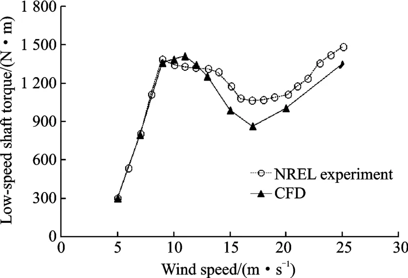
Fig.1 Low-speed shaft torque of the rotor from CFD and NREL experiments
1.1Flow around rotating blade
Features of the flow around the rotating blade are investigated based on the obtained CFD results.Stream lines around the blade at various wind speeds are shown in Fig.2.At the speed of 9 m /s,flow keeps attached to most area of the blade while slight separation happens only near the trailing-edge in a small area.Stream lines remain 2-D patterns in the attached flow area while present 3-D patterns pointing from the inboard to the outboard in the separation area.As the speed increases to 13 m /s,the separation area expands and the 3-D features of stream lines become much notable.At the speed of 20 m /s,the whole blade is covered by separated flow.Massive stream linesare going through the separation vortex which looks like a long and large tunnel on the blade.The above phenomena indicate that there is a close relation between the flow separation and the 3-D spanwise flow features on the blade.The spanwise flow in the separation vertex can only be generated by the rotational effects since there is no such spanwise flow on a non-rotating blade.

Fig.2 Stream lines around the rotating blade
For simplicity of the analysis,a typical 3-D stream line going through the separation vortex is extracted from the flow field at the wind speed of 13 m/ s,as shown in Fig.3.The stream line goes from point A to point B through a path determined by the separation vortex,and then suddenly changes its trajectory from the chordwise direction to the spanwise direction.Point B is the location at which the sudden change of direction happens.A mechanical interpretation for that can be given as follows: Air particles are accelerated to rotate along with the blade during the process from point A to point B.In this process,their relative velocity to the blade slows down to about zero at point B.That means the air particles at point B have very small chordwise momentum in the rotating reference frame while simultaneously they are under great centrifugal force in the spanwise direction,and therefore they take a sudden turn from the chordwise direction to the spanwise direction.
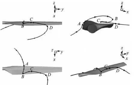
Fig.3 3-D stream line at the wind speed of 13 m/s
According to the mass conservation law,the separation vortex must shrink in volume as some quantity of air is pumped by centrifugal force to the outboard of the blade.That makes a great distinction in volume and shape of the separation vortex between a section of a rotating blade and a static airfoil.A demonstration of this distinction in conditions of trailing-edge separation and complete separation is shown in Fig.4.
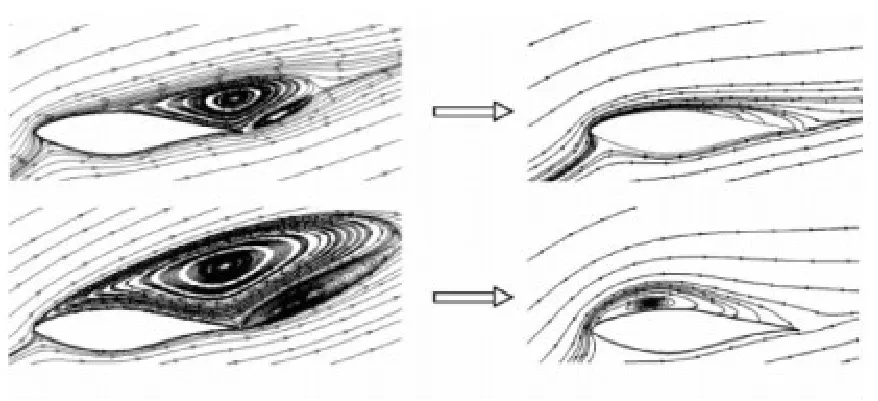
Fig.4 Separation vortices on a static airfoil (left) and a section of rotating blade (right)
1.2Stall delay correction model
A new model for correcting the stall delay due to rotational effects is established based on the above analysis of the flow around rotating blades.In the present model,the angle of attack (AoA) and the lift coefficient CLof airfoils are corrected to include the influence of rotating.
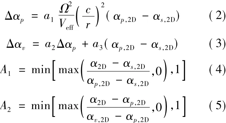
The corrected AoA is

where
The corrected CLis expressed in three segments as follows

where
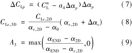
Definitions of the parameters in Eqs.(1)—(9) are given by
α3D: corrected AoA for blade sections
α2D: original AoA of the airfoil
αs,2D: airfoil AoA as trailing-edge separation starts
αp,2D: airfoil AoA corresponding to the maximum CL
αv,2D: airfoil AoA corresponding to the minimum CLin deep stall
αEND: AoA till which the correction is performed and the value of π/2 is suggested
CL,3D: corrected CLfor blade sections
CL,2D: CLof the airfoil
CLv,2D: minimum CLof the airfoil in deep stall
c : chord length of blade sections
r : radial position of blade sections
Ω: angular speed of the rotor
Veff: effective velocity magnitude of inflow
a1,a2,a3,a4,e1,e2: empirical constants assigned the following values for calculations in this paper.a1= 2.5,a2= 1.5,a3= 0.8,a4= 0.002,e1=1.5,e2= 2.0.
2 Discussion
2.1Correction for AoA
Key AoA in the proposed model are demonstrated in Fig.5,taking the S809 airfoil and the 47% span section of the NREL PhaseⅥblade as an example.These key AoAs can be distinguished easily in a lift coefficient curve.
On the one hand,the shrink of separation vortex is positively correlated to the quantity of air transported by centrifugal force which is proportional to Ω2,and consequently the stall delay,which is mainly caused by the shrink of separation vortex,can be supposed positively related to Ω2.On the other hand,the shrink of separation vortex should be negatively related to the quantity of air added into the separation vortex from the inflow,and the stall delay can thus be supposed negatively related to the effective velocity magnitude of inflow.As a result,the stall delay is supposed proportional to Ω2/Veffas shown in Eq.(2).
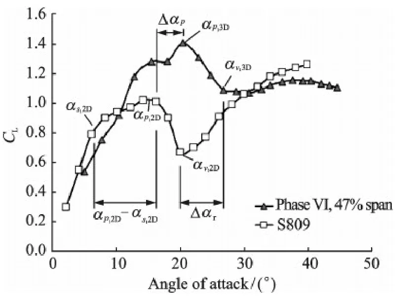
Fig.5 Key angles of attack on lift coefficient curves of the airfoil and the rotating blade section
The stall delay is assumed to be more significant with the increase of c/r according to Du et al[8].Therefore,an item of (c/r)nis also included in Eq.(2).The index n is assigned a value of 2 in calculations of this paper.There is an extra item of αp,2D-αs,2Din Eq.(2).It represents the AoA range between the light stall and the deep stall of the airfoil.The item means that the stall delay on a rotating blade is related to the aerodynamic performance of the airfoil on which it is based.
2.2Correction for lift coefficient
Lift coefficient is corrected in three segments as follows.The first segment is before the maximum lift coefficient reached,the second segment is between the maximum and the minimum lift coefficients,and the third one is after the minimum lift coefficient.The expression of the corrected lift coefficient for the first segment is a part of Eq.(6).It is rewritten as

where ΔCLprepresents the correction of the maximum lift coefficient and can be calculated by Eq.(7).As previously analyzed the flow around a rotating blade,separation vortex does not vanish in the process of stall delay although its volume is significantly reduced.Consequently,it still makes the lift coefficient a little bit smaller than that of the ideal flow without separation.The change in lift coefficient is considered in Eq.(7) by introducing an item of-a4Δαp.
The corrected lift coefficient for the second segment is

The CLv,3Dis a key value representing the corrected minimum lift coefficient which is determined by Eq.(8) based on an assumption that the corrected minimum value lies on the straight line determined by the origin (0,0) and the uncorrected location of the minimum lift coefficient.
The corrected lift coefficient of the third segment is

The function of Eq.(12) is to fit the corrected lift coefficient with the uncorrected lift coefficient at the higher AoA.
3 Validations
As a validation,corrections with the present model are carried out on the NREL PhaseⅥblade.Lift coefficient data of various sections of the blade are shown in Fig.6.Most data from the model agree with those from NREL' s experiment at 30%,47% and 80% of the span,indicating that the model is valid at sections near the root,middle and tip of the blade.
For a further validation,the present model is applied to actuator line (AL) method[16],which is based on a combination of CFD method and the lift line concept.The stall delay due to rotational effects cannot be predicted by the AL method itself since the blade geometry is not described.The computing results of lift coefficient by the AL method with and without the present model are shown in Fig.7,together with NREL's experimental data.At the wind speed of 7 m/s,data from computations with and without the model are close to each other,which is reasonable since almost no flow separation exists at this wind speed.At the higher wind speeds of 13,15 and 20 m/s,the computational data with the model agree with the experimental data much better than those without the model,especially at the lower values of r/ R.The validation results indicate that stall delay of the NREL PhaseⅥblade due to rotational effects can be well corrected by the present model in engineering applications.
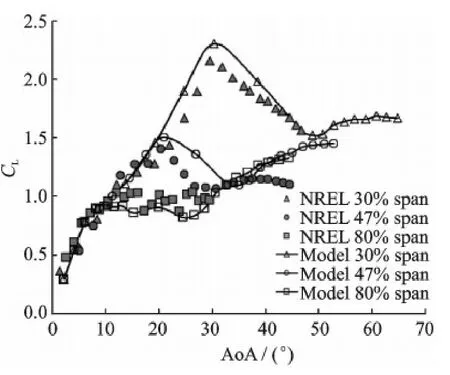
Fig.6 Lift coefficient data for various sections of the blade
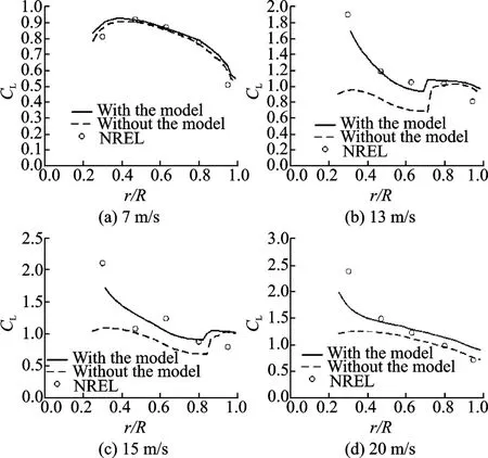
Fig.7 Lift coefficient from AL computations with and without the model
4 Conclusions
A new stall delay model is established for more accurate predictions of aerodynamic load of wind turbine blades.Features of flow around a rotating blade are analyzed firstly.It is found that a notable shrinkof the separation vortex happens since a lot of air in the vortex is transported by centrifugal force to the blade outboard.This phenomenon is considered as the major reason for the stall delay.The present model is then built based on the above analysis.Multiple factors that may influence the rotational effects including rotating speed,inflow velocity,local chord length and radial positions are comprehensively considered in the model.In addition,typical points on lift coefficient curve of airfoils are defined as key points in the correcting process,i.e.,the start point of trailing-edge separation,the peak point and the lowest point on the lift coefficient curve.Finally,the model are validated and the results show that the aerodynamic force affected by the stall delay can be well corrected by the proposed model.A limitation of the present work is that validations are only performed on the NREL PhaseⅥblade.It is valuable to test the model in aerodynamic predictions for more turbines and to further improve its performance.
Acknowledgements
This work was funded jointly by the National Basic ResearchProgramof China (″973″Program )(No.2014CB046200),the National Natural Science Foundation of China (No.51506088),the Fundamental Research Funds for the Central Universities (No.NS2014010),the Natural Science Foundation of Jiangsu Province (No.BK2014059),and the Priority Academic Program Development of Jiangsu Higher Education Institutions.
References:
[1]SØRENSEN J N.General momentum theory for horizontal axis wind turbines[M].Cham: Springer International Publishing Switzerland,2016.
[2]LEE H M,WU Y.A tomo-PIV study of the effects of freestream turbulence on stall delay of the blade of a horizontal-axis wind turbine[J].Wind Energy,2015,18(7) : 1185-1205.
[3]SICOT C,DEVINANT P,LOYER S,et al.Rotational and turbulence effects on a wind turbine blade: Investigation of the stall mechanisms[J].Journal of Wind Engineering and Industrial Aerodynamics,2008,96 (8/ 9) : 1320-1331.
[4]YU G,SHEN X,ZHU X,et al.An insight into the separate flow and stall delay for HAWT[J].Renewable Energy,2011,36(1) : 69-76.
[5]SNEL H,HOUWINK R,BOSSCHERS J.Sectional prediction of lift coefficients on rotating wind turbine blades in stall: ECN-C-93-052[R].Netherlands:[s.n.],1994.
[6]CHAVIAROPOULOS P K,HANSEN M O L.Investigating three-dimensional and rotational effects on wind turbine blades by means of a quasi-3D Navier-Stokes solver [J].Journal of Fluids Engineering,2000,122(2) : 330-336.
[7]RAJ N V.An improved semi-empirical model for 3-D post-stall effects in horizontal axis wind turbines[D].Urbana-Champaign: University of Illinois,2000.
[8]DU Z,SELIG M S.A 3-D stall delay model for horizontal axis wind turbine performance prediction: AIAA-98-0021[R].[S.l.]: AIAA,1998.
[9]BAK C,JOHANSEN J,ANDERSEN P B.Three-dimensional corrections of airfoil characteristics based on pressure distributions[C]∥2006 European Wind Energy Conference Proceedings.Athens:[s.n.],2006.
[10]LINDENBURG C.Investigation into rotor blade aerodynamics: ECN-C-03-025[R].Netherlands:[s.n.],2003.
[11]CORRIGAN J J,SCHILLINGS J J.Empirical model for stall delay due to rotation[C].American Helicopter Society Aeromechanics Specialists Conference Proceedings.San Francisco:[s.n.],1994.
[12]BRETON S P,COTON F N,MOE G.A study on rotational effects and different stall delay models using a prescribed wake vortex scheme and NREL phase VI experiment data[J].Wind Energy,2008,11(5) : 459-482.
[13]SANDERSE B,PIJL S P,KOREN B.Review of computational fluid dynamics for wind turbine wake aerodynamics[J].Wind Energy,2011,14(7) :799-819.
[14]ZHONG W,WANG T G.Numerical analysis of the wind turbine blade-tip vortex[J].Journal of Nanjing U-niversity of Aeronautics&Astronautics,2011,43(5) : 640-644.(In Chinese)
[15]ZHONG W,WANG T G.Numerical analysis of transition effect on stall performance of wind turbine airfoils and blades[J].Acta Aerodynamica Sinica,2011,29 (3) : 385-390.(In Chinese)
[16]SØRENSEN J N,SHEN W Z.Numerical modeling of wind turbine wakes[J].Journal of Fluids Engineering,2002,124(2) : 393-399.
Dr.Zhong Wei is a Lecturer in Nanjing University of Aeronautics and Astronautics (NUAA).His research interests are wind engineering and computational fluid dynamics.
Dr.Wang Tongguang is the Director of Jiangsu Key Laboratory for Wind Turbine Design at NUAA.He was desig-nated as the Chief Scientist of the″973 Program″by the Ministry of Science and Technology,China in 2007,and successfully completed the project″Fundamental Study of Large Scale Wind Turbine Aerodynamics″.As the Chief Scientist again,he is now in charge of another project of the″973 Program″—″Key Mechanical Issues and Design of Large Scale Wind Turbines″.Prof.Wang graduated from NUAA with B.S.degree and M.S.degree in 1983 and 1988,respectively,and he received his Ph.D.degree from the University of Glasgow in 1999 and has been a postdoctoral fellow at the University of Glasgow from October 1999 to August 2001.During this period,he was invited to join in the Wind Turbine Unsteady Aerodynamics Experiment-Blind Comparison,organized by the National Renewable Energy Laboratory (NREL) of USA.His paper″An examination of key aerodynamic modeling issues raised by the NREL Blind Comparison″was awarded The Best Paper Prize by ASME/AIAA in 2002.
(Executive Editor: Zhang Tong)
杂志排行
Transactions of Nanjing University of Aeronautics and Astronautics的其它文章
- Gravity Effect on the First Natural Frequency of Offshore Wind Turbine Structures
- Numerical Analysis on Motion of Multi-column Tension-Leg-Type Floating Wind Turbine Basement
- Coupled Aerodynamic and Hydrodynamic Analysis of Floating Offshore Wind Turbine Using CFD Method
- CFD-Based Load Calculation Method for Monopile Support Configuration of Offshore Wind Turbine
- Simulation of SLD Impingement on Wind Turbine Blade Airfoil
- Improvement of Mechanical,Dynamic-Mechanical and Thermal Properties for Noil Ramie Fiber Reinforced Polyethylene Composites
