Numerical Simulation of Wind Turbine Wake Characteristics in Uniform Inflow
2016-05-12LiRennianMaRuijieLiDeshunLiYinranWangChengzeSchoolofEnergyandPowerEngineeringLanzhouUniversityofTechnologyLanzhou730050ChinaGansuProvincialTechnologyCentreforWindTurbinesLanzhou730050ChinaKeyLaboratoryofFluidmachinerya
Li Rennian,Ma Ruijie,Li Deshun,2,3,Li Yinran,2,3,WangChengze.School of Energy and Power Engineering,Lanzhou University of Technology,Lanzhou 730050,P.R.China;2.Gansu Provincial Technology Centre for Wind Turbines,Lanzhou 730050,P.R.China;3.Key Laboratory of Fluid machinery and Systems,Lanzhou 730050,P.R.China (Received 8 January 205; revised 20 February 204; accepted 5 March 204)
Numerical Simulation of Wind Turbine Wake Characteristics in Uniform Inflow
Li Rennian1,2,3*,Ma Ruijie1,Li Deshun1,2,3,Li Yinran1,2,3,WangChengze1
1.School of Energy and Power Engineering,Lanzhou University of Technology,Lanzhou 730050,P.R.China;
2.Gansu Provincial Technology Centre for Wind Turbines,Lanzhou 730050,P.R.China;
3.Key Laboratory of Fluid machinery and Systems,Lanzhou 730050,P.R.China (Received 18 January 2015; revised 20 February 2014; accepted 5 March 2014)
Abstract:Flow field around a two-bladed horizontal-axis wind turbine (HAWT) is simulated at various tip speed ratios to investigate its wake characteristics by analyzing the tip and root vortex trajectories in the near-wake,as well as the vertical profiles of the axial velocity.Results show that the pitch of the tip vortex varies inversely with the tip speed ratio.Radial expansion of the tip vortices becomes more obvious as the tip speed ratio increases.Tip vortices shed not exactly from the blade tip but from the blade span of 96.5%—99% radius of the rotor.The axial velocity profiles are transformed into V-shape from W-shape at the distance downstream of eight rotor diameters due to the momentum recovery.
Key words:horizontal-axis wind turbine(HAWT) ; wake characteristics; tip speed ratio; vortex trajectory
CLC number: TN925Document code: AArticle ID: 1005-1120(2016)01-0045-08
* Corresponding author,E-mail address: lirn@ lut.edu.cn.
How to cite this article: Li Rennian,Ma Ruijie,Li Deshun,et al.Numerical simulation of wind turbine wake characteristics in uniform inflow[J].Trans.Nanjing Univ.Aero.Astro.,2016,33(1) : 45-52.
http: / /dx.doi.org/10.16356/j.1005-1120.2016.01.045
0 Introduction
Wind turbines clustered in wind farms may result in aerodynamic interactions when one wind turbine of them operates in the wake of other turbines,which would reduce power output because of the velocity deficit introduced by the upstream wind turbine and increase the turbulence intensity in the wake,consequently increasing the dynamic loads and shortening the lifespan of the wind turbine.Hence,the wake of wind turbine has been an intense topic of research during the last decades.
In the study of wind turbine wakes a distinct division is typically made between the near wake and the far wake.The near wake is estimated to be one diameter downstreamby Vermeer et al.[1].In this region,the wake geometry determines the character of the flow field and significantly influences the performance of the turbine.The far-wake is the region in which the actual rotor shape is less important,but more focus should be put on wake modeling,wake interference (wake farms),turbulence modeling and topographic effects.
A lot of comprehensive wind tunnel measurements have been conducted to study the wake using hotwire anemometry and partical imagevelocimetry(PIV ).Ebertand Wood[2-4],Hu et al.[5-7],Gao et al.[8-9]measured the three-dimensional (3 -D ) nearwake flow field of horizontal-axis wind turbine (HAWT) models with various tip speed ratios,and got two-dimensional (2 -D) tip vortex trajectory.Though a lot of experiments have been conducted to investigate the vortices,it is still hard to depict the detail of 3 -D movement of the tip vortices by 2 -D simplification.Whale et al.[10]made PIV investigation,demonstrating that the behaviour of the wake might be insensitive to the blade Reynolds number at the similar tip speed ratio.
Beacause of the limitation of measuring extent and complexity of the flow field in experi-ment,the semi-analytical far wake models have been proposed to describe the wake velocity after the initial expansion[11-12].The wake models neglect the details of the flow field around turbine and assume rotational symmetry and linear wake expansion with distance.However,a number of parameters,such as the length and expansion rate of near wake,are needed to be empirically determined.
Full 3-D computations employing the Reynolds-Averaged Navier-Stokes equations have been carried out by many researchers,e.g.Sørensen et al[13].Computational fluid dynamics (CFD) methods have been proven to be suitable for predicting and understanding the flow around wind turbines as they can provide detailed information on the flow field,including the blade-tip vortex[14].However,it requires massive computer resources to accurately simulate both the flow over the turbine blades and the flow in the near and far wake.
Owing to the unique structure of rotor blades,the construction of computational grids becomes even harder.Moreover,the optimal operating condition for most turbines is close to stall,and the flow field exhibits the scales ranging from the size of small eddies in the boundary layer on the blade to the distance between wind turbines.
Here,the distances of the inlet and the outlet to the rotor plane are extended to 3d and 18d(d is the rotor diameter),respectively,so it is far enough to investigate the details of the wind turbine wake.The hexahedral mesh with boundary layer is constructed.The wind turbine wakes are simulatedusingReynolds-averagedNavier-Stokes (RANS) equations for four different tip speed ratios.The objective of the research is to study the wake characteristics of the wind turbine by the full 3-D numerical method,including 3-D vortex structure in near wake,the relationship between the wake structure and the tip speed ratio,flow state,and the velocity deficit and recovery downstream of the wind turbine as well.
1 Wind Turbine Model and Computational Mesh
The wind turbine model in this numerical study is a 2-bladed upwind horizontal axis wind turbine with a rotor diameter of 500 mm for the size limitation of the wind tunnel as a guidance for the experiment.The airfoils used in blade are from the NACA44XX family,from NACA4412 to NACA4430.The blade is twisted from 10.01°at the root to-1.06°at the tip.The chords vary from 13.446 mm(NACA4430) at the root to 37.027 mm (NACA4412) close to the tip.The computational turbine models are shown in Fig.1.

Fig.1 Computational wind turbine model
The computational domain for the wind turbine placed in the wind tunnel is illustrated in Fig.2.The domain consists of two parts,i.e.,the rotating zone and the stationary zone (wind tunnel part).The wind turbine is placed at a distance of 3d from the inlet and a distance of 18d to the outlet.The outlet of the rotating part is extended to 1d from the rotor center to capture vortices in near wake region more easily.

Fig.2 Computational domain with rotating and stationary zone
In order to simulate the flow fields more accurately,the O-type blocks are used to cover the span of the blades and the hub to generate the boundary layer grid,with 11 inflation layers,and the spacing ratio is 1.5 in the normal direction.The first height in the normal direction from the surfaces is 0.098 mm.The total number of the numerical grid cells is 15.86 million,consisting of hexahedral meshes over the entire domain.Theblade is meshed along the chord-wise direction by 42 nodes on both the suction and pressure surfaces with a higher concentration near the leading and the trailing edge regions.There are 152 nodes along the span-wise direction.Furthermore,fine meshes are used near both the blade tip and root.The 48 points are distributed in the radial direction along the tip of the blade to the cylinder of the rotating zone (the interface) to make the spacing be 1.2 mm to efficiently capture the tip vortices,as shown in Fig.3.

Fig.3 Grid distribution around rotor blades
2 Boundary Conditions and Numerical Methods
Uniform incoming velocities are applied as the inlet boundary conditions in the present study.The rotation speed of the wind turbine is kept constant 2 400 r/min.The turbine operates in four different tip speed ratios,λ= 5, 6,7,8 (λ=,where n is the rotation speed and V0the incoming wind speed),corresponding to the incoming wind speeds of 12.57,10.47,8.98,7.83 m /s,respectively.It should be noted that a typical two-bladed HAWT on a wind farm usually has the tip speed ratios λ= 5-8.
2.1Governing equations
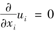
The present numerical simulation is carried out using an RANS solver,which employs a cellcentered finite-volume method based on a multidimensional linear reconstruction scheme.As the resulting maximum speed on the suction side does not exceed the Mach number of 0.3,the incompressible RANS equations are used,where the mass and momentum conservation equations are as follows
Continuity equation
Momentum equation
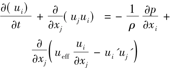
where ρ is the air density,uithe average velocity,p the pressure,ueffthe coefficient of virtual viscosity,and ui' the fluctuating velocity.i,j = 1,2,3,represent the three components in Cartesian coordinate system.
2.2Turbulence modelling
In conjunction with governing equations,the re-normalization group (RNG) k-ε model is used in turbulence modeling.The convective terms are discretized using the second-order upwind differencing scheme.Numerous experiments have shown that the near-wall region can be largely subdivided into three layers,namely the viscous layer (y+≤5),the buffer layer (30<y+<500 ),and fully turbulent layer[15].In this study,the first height in the direct vicinity of the wall is 0.098 mm and y+<20 in all cases,which is between the viscous layer and the buffer layer.The enhanced wall treatment for the z-equation,a near-wall modeling method that combines a twolayer model with so-called enhanced wall functions,is used to achieve the goal of having a nearwall modeling approach,which possesses the accuracy of the standard two-layer approach for fine near-wall meshes and,at the same time,does not significantly reduce accuracy for wall-function meshes.This numerical method has been validated by accurate prediction of the pressure distribution along the blade by Li et al.[16].So it is applicable to perform the rotor blade calculation by the RNG k-ε model.
3 Results and Discussions
3.1The near wake structure
The three-dimensional vortices structures at λ = 8,7,6,5,as shown in Fig.4,are indicated by vortex core region through the Q-criterion,a method that detects vortices iso-surfaces of thesecond invariant of velocity gradient tensor of the same lever.It can be easily found that the vortex strength increases with the decrease of tip speed ratio,as there is a relatively short axial extent of the vortex core region when λ= 8,7.In order to extent the vortex core region to the outlet of the rotating part when λ= 8,7,the value of the criteria lever should be reduced.As shown in Fig.5,the vortices structures dominated by two counter-rotating helical vortex pairs,shedding from two blades tips and roots,are better described.
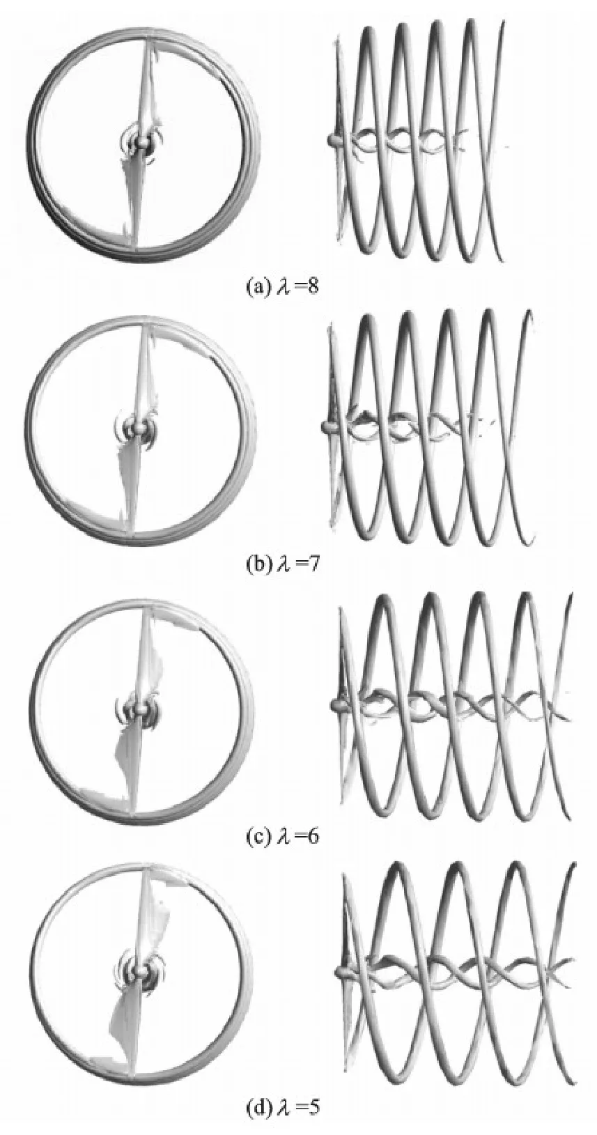
Fig.4 Vorticity iso-surface
It can be seen from Fig.4 that the separation over the blade depends on the change of tip speed ratio.For λ= 8,the flow is nearly attached,and the well-defined vortex structures are shed from the blade tips.While for the highest wind speed case,λ= 5,the flow is massively separated nearly over the entire blade span.It exhibits the more seriousness of the separation as the tip speed ratio decreases.This is in good agreements with the limiting streamlines on the blade suction side,as shown in Fig.6.With the decreasing of tip speed ratio,the flow separation varies from 50% coverage of the suction side at λ= 8 to nearly whole over the blade at λ= 5,which is closely related to the variation of the angle of attack along the turbine blades as a function of tip speed ratio,as shown in Fig.7.The angle of attack,referring to a relative flow velocity can be calculated using an incoming wind speed and a global pitch angle relative to the plane of rotation.When the turbine is operating in a constant pith angle,the angle of attack mainly depends on the tip speed ratio.
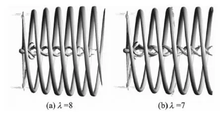
Fig.5 Vorticity iso-surface at low lever
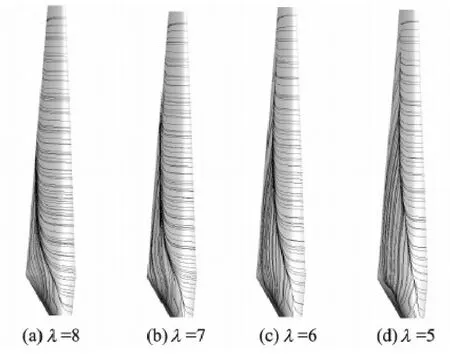
Fig.6 Limiting streamlines on the suction side of the blade
The wake of wind turbine is three-dimensional,and obvious radial expansion of the tip vortices can be observed from Figs.4,5.It can be easily found that the radial expansion of tip vortices becomes more obvious as the tip speed ratio increases.The trend of the radial expansion of the tip vortices is slowing down with the axial distance to the rotor plane increasing.However,the pitch,the axial distance between the adjacent tip vortex cores,is constant,but varies inversely with the tip speed ratio.
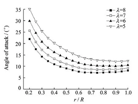
Fig.7 Angle of attack variation along the blade for various λ
In order to analyze the characteristics of tip vortices quantitatively,we depict the position of the tip vortex core at the 10°azimuth plane in the rotating zone by the normalized radius along the axial direction,as shown in Fig.8.For easy observation and analysis,the centers of the adjacent tip vortex cores are connected at the 10°azimuth plane,where the tip vortex is just trailed from the blade and the vorticity magnitude reaches the maximum according to the results of PIV experiment[17].
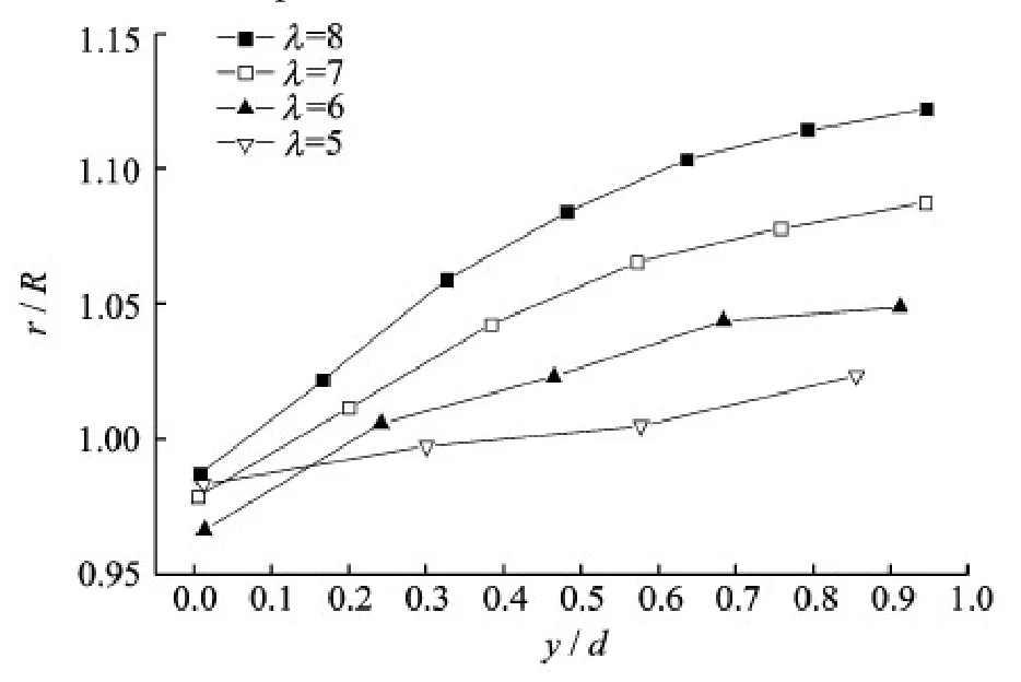
Fig.8 Normalized radial position of the tip-vortex cores at 10°azimuth plane along the axial direction for various λ
It shows that the distribution of tip vortex cores are similar among λ=8,7,6,5.The radii of the position of the vortex cores are getting larger along the axial direction.The tangent slopes of connections of tip vortex cores are steeper as the increase of tip speed ratio.And the tangent slopes are decreasing as the distance to the rotor plane increases.y/d =0 is regarded as the position at which tip vortex are just trailed.It is found that the shedding points are not exactly from the tip,but from a region near the tip,ranging from 96.5% R to 99% R (R is the radius of the rotor).The higher the tip speed ratio is,the closer the vortex trailing position is to the tip,except for the case of λ= 5,where the trailing position is closer to the tip than the cases of λ= 6 and λ= 7.This phenomenon may be caused by the obvious fluctuation of the vortex shedding due to the severe flow separation resulted from the 3-D unsteady characteristics at λ=5.
3.2Velocity profiles in the wake
The vertical profiles of the time-averaged normalized axial velocities for one upstream and several normalized downstream locations behind the turbine for -1<z/d<1 and at the hub center (x/d = 0) are presented in Fig.9.The region of-0.5<z/d<0.5 responds to the rotor.It can be seen that the velocity profiles are near-symmetrical about the hub center when the effect of the tower and the boundary layer on the tunnel wall are neglected.The axial velocities (Vy) have been normalized with the corresponding reference incoming wind speed and therefore the normalized velocities at inlet are 1.The profiles show the velocity deficit due to the momentum extraction of the wind turbine and the consequent recovery behind the wind turbine.
At the upstream location of y/d =-0.5,it can be observed that there are approximately 3.5% lower than the reference wind speeds for all the cases in the region of-0.5<z/d<0.5 due to the blockage and stagnation effect of the wind turbine.After the rotor,a velocity deficit zone appears.At y/d = 1,the distinct W-shaped velocity profiles appear as the turbine has extracted momentum from the incoming airflow and produced a wake when the airflow passes through the wind turbine instantly.It can be seen that the velocity profiles are closely associated with the tip speed ratio.This may be caused by the flow state on the turbine blades.Since the largest tip-tospeed-ratio corresponds to the smallest angle of attack,the low flow separation occurs as shown in Figs.6,7,leading to large proportion of energy extraction from the incoming flow.
It can also be proved by the cases at the other tip speed ratios that the velocity deficits become large as the tip speed ratio increases.At the peak of the W-shaped profile,the lowest velocity deficit is found in the zone of-0.1<z/d<0.1,which corresponds to the hub region of the wind turbine.The velocity deficits change rapidly on both sides of z axis.As the wake structure is approximately symmetrical,only the region of z>0 is discussed here.It can be found that the peaks are located at z =0.15d and z =0.5d,corresponding to the regions near the hub and the tips of turbine,respectively.
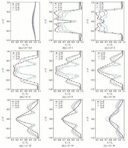
Fig.9 Comparison of vertical profiles of y-velocity for one upstream and several normalized downstream locations with-1<z/d<1 at hub center (x/d =0)
Moreover,it can be observed that velocity profiles at different tip speed ratios retain similar until y/ d =8,where the axial velocity profiles transform from W-shaped to V-shaped due to momentum recovery.The velocity deficits in the central zone (-0.15<z/ d<0.15) become smaller as the axial distance to the rotor plane increases,which is opposite to the behavior before y/d =8.After this cross-section,y the velocity deficits in the wake have been reduced to theoutlet at y/d = 18.However,it has been found that the wake effects still remain noticeable even in the far wake as long as 18d.This proves that the assumption of the far downstream velocity in the blade momentum theory widely used in wind turbine aerodynamic calculation has a real physical foundation.Besides,the velocity profiles at λ= 7,6,5 are apparently different from those at λ=8 after y/d =8.This may be associated with the tip vortices,mixing the low velocity fluid in wake with outside free flow and transferring the momentum of free flow into the wake.And it causes the expansion of wake and the recovery of velocity deficit.As λ=8 corresponds to the smallest incoming velocity,the ability to redistribute the momentum from outside the wake into the center of the wake is relatively weak.
There exists considerable difficulty in defining the wake width due to the complexity of turbulent distribution in the actual wind field.The tip vortex trajectories of a portion of the near wake have been obtained by enlarging rotating domain,however,it is still hard to define the whole wake width from the present numerical results.Therefore,the wake width has been defined qualitatively as the region where the wind speed ratio is smaller than 0.99 by Ref.[18].It can be found that,before y/d =1,the wake width is rigidly dependent on the tip speed ratio as shown in Fig.8.The wake is then widened and becomes stable gradually as the downstream distance to the rotor plane increases.
4 Conclusions
The numerical simulation of the flowfield around a two-bladed HAWT at different tip speed ratios is carried out to analyze the wake profiles and get a better understanding of the wake structure.The main contents include the 3-D vortex trajectories,the position of the tip vortex cores in near-wake and the vertical profiles of axial velocity.The salient observations as a consequence of this investigation are summarized as follows:
(1) It is showed that the wake behind the wind turbine consists of a system of intense and stable helical vortices generated by the wind turbine blades.The vortex strength enhances with the decrease of tip speed ratio.The pitch of the tip vortex is constant and varies inversely with the tip speed ratio.The radial expansion of tip vortex becomes more obvious as the tip speed ratio increases.However,the trend of the radial expansion is slowing down with increase of the distance to the rotor plane.
(2) It is found that the shedding points of the tip vortices are not exactly from the blade tip,but from a region near the tip,ranging from 96.5% R to 99% R.The radius of shedding point gets larger as the tip speed ratio increases,except for the specific case at low tip speed ratio,where severe flow separation may occur.It is supposed that the separation point is associated with the flow state over the blades.
(3) As the momentum extraction from the upstream flow,the W-shaped and near-symmetrical axial velocity profiles can be seen before y/d = 8.The normalized velocity deficits are strongly related to the tip speed ratio.The largest velocity deficits are observed in the tip vortex regions of the wind turbine at the largest tip speed ratio considered.The velocity deficits decrease due to momentum recovery with the distance to the rotor plane increasing before y/d =8,while the profiles of the velocity deficits in the central zone is opposite.At y/d = 8,the axial velocity profiles are transformed from W-shape into V-shape due to momentum recovery.However,the wake effects are still quite noticeable in the far wake at a distance of 18 rotor diameters.
Acknowledgements
This work was supported partly by the National Basic ResearchProgramof China(″973″Program )(No.2014CB046201),the National Natural Science Foundation of China (No.51166009),the National High Technology ResearchandDevelopment Programof China(No.2012AA052900),the Natural Science Foundation of Gansu Province,China (No.1308RJZA283,145RJZA059),and the Gansu Province University Scientific Research Project,China (No.2013A-026).The authors would like to extend heartfelt thanks to the reviewers for their careful revision and precious suggestion and would also like to thank Mr.Li Qiuyan and Mr.Liu Heng for their assistance.
References:
[1]VERMEER L J,SøRENSEN J N,CRESPO A.Wind turbine wake aerodynamics[J].Progress in Aerospace Sciences,2003,39(6/7) : 467-510.
[2]EBERT P R,WOOD D H.The near wake of a model horizontal-axis wind turbine part 1: Experimental ar-rangement and initial results[J].Renewable Energy,1997,12(3) : 225-243.
[3]EBERT P R,WOOD D H.The near wake of a model horizontal-axis wind turbine part 2: General features of the three-dimensional flowfield[J].Renewable Energy,1999,18: 513-534.
[4]EBERT P R,WOOD D H.The near wake of a model horizontal-axis wind turbine part 3: Properties of the tip and root vortices[J].Renewable Energy,2001,12: 461-472.
[5]HU Danmei,DU Chaohu.Near wake of a model horizontal-axis wind turbine[J].Journal of Hydrodynamics: Ser B,2009,21(2) : 285-291.
[6]Dong X F.Gas-solid flow erosion wear behavior of key materials of the wind turbine[D].Xinjiang: Xinjiang U-niversity,2013.
[7]HU Danmei,OUYANG Hua,DU Chaohu.An experimental study of the wake structure of model horizontalaxis wind turbine[J].Acta Energiae Solaris Sinica,2011,27(6) : 606-612.(in Chinese)
[8]GAO Zhiying,WANG Jianwen,DONG Xueqing,et al.Experimental investigation on near wake structure of horizongtal axis wind turbine[J].Acta Energiae Solaris Sinica,2011,32(6) : 897-900.(in Chinese)
[9]GAO Zhiying,WANG Jianwen,DONG Xueqing,et al.PIV experiment on of the tip vortices of wind turbine [J].Journal of Engineering Thermophysics,2010,31 (3) : 414-418.(in Chinese)
[10]WHALE J,ANDERSON C G,BAREISS R,et al.An experimental and numerical study of the vortex structure in the wake of a wind turbine[J].Journal of Wind Engineering and Industrial Aerodynamics,2000,84(1) : 1-21.
[11]FRANDSEN S,BARTHELMIE R,PRYOR S,et al.Analytical modelling of wind speed in large offshore wind farms[J].Wind Energy,2006,9(1/2) : 39-53.
[12]XU Bofeng,WANG Tongguang.Wind turbine aerodynamic performance prediction based on free wake/panel model coupled method[J].Journal of Nanjing University of Aeronautics and Astronautics,2011,43(5) : 592-597. (in Chinese)
[13]SøRENSEN N N,MICHELSEN J A,SCHRECK S.Navier-Stokes predictions of the NREL phaseⅥrotor in the NASA AMES 80 ft×120 ft wind tunnel[J].Wind Energy,2002,5(2/3) : 151-169.
[14]ZHONG Wei,WANG Tongguang.Numerical analysis of the wind turbine blade-tip vortex[J].Journal of Nanjing University Aeronautics and Astronautics,2011(5) : 640-644.(in Chinese)
[15]VERSTEEG H K.An introduction to computational fluid dynamics: The finite volume method[M].2th Ed.Beijing: Beijing World Publishing Corporation,2010: 72-80.
[16]LI Deshun,LI Rennian,WANG Xiuyong,et al.Investigation of three-dimensional effect on blades of wind turbine based on field experiments[J].Applied Mathematics and Mechanics,2013,34(10) : 1073-1082.(in Chinese)
[17]YANG Zhentao.Research on the wind turbine blade tip vortex field dynamics based on the 3D PIV[D].Hohhot City: Inner Mongolia University of Technology,2013.(in Chinese)
[18]MO Jang-Oh,CHOUDHRY A,ARJOMANDI M,et al.Effects of wind speed changes on wake instability of a wind turbine in a virtual wind tunnel using large eddy simulation[J].Wind Engineering and Industrial Aerodynamics,2013,117: 38-56.
Dr.Li Rennian is the Vice President,professor and doctoral adviser in Lanzhou University of Technology,specializing in the research of wind turbine aerodynamics and fluid machinery.
Ms.Ma Ruijie is studying in Lanzhou University of Technology for the M.S.Degree.Her current research interests focus on the wind turbine aerodynamics.
Dr.Li Deshun is the deputy director of Gansu Provincial Technology Centre for Wind Turbines,associated professor and master tutor of Lanzhou University of Technology.His main research interests lie in the wind turbine aerodynamics.
Mr.Li Yinran is an Ph.D.candidate in Lanzhou University of Technology.His main research interests are the wind turbine aerodynamics.
Mr.Wang Chengze is a postgraduate student in Lanzhou University of Technology and his research interests are mainly about wind turbine aerodynamics.
(Executive Editor: Zhang Tong)
杂志排行
Transactions of Nanjing University of Aeronautics and Astronautics的其它文章
- Gravity Effect on the First Natural Frequency of Offshore Wind Turbine Structures
- Numerical Analysis on Motion of Multi-column Tension-Leg-Type Floating Wind Turbine Basement
- Coupled Aerodynamic and Hydrodynamic Analysis of Floating Offshore Wind Turbine Using CFD Method
- CFD-Based Load Calculation Method for Monopile Support Configuration of Offshore Wind Turbine
- Simulation of SLD Impingement on Wind Turbine Blade Airfoil
- Improvement of Mechanical,Dynamic-Mechanical and Thermal Properties for Noil Ramie Fiber Reinforced Polyethylene Composites
